
Related Manuals for Creality XL


Summarization of Contents
Important Safety Instructions
Skill Level and Safety Precautions
Project requires advanced knowledge; handle with care.
Machine Operation Safety
Never reach into the machine while running; disconnect power for maintenance.
Handling Sharp Edges Safely
Sand sharp edges on metal parts for safety.
Electrical Wiring Safety
Ensure secure connections when lengthening wires.
Firmware Update Considerations
Update firmware for new volume; no support provided.
Before You Begin
Document Your Printer Setup
Take pictures of detail areas like motors and wiring before disassembly.
Perform Kit Inventory Check
Inventory all kit parts before disassembly to address issues early.
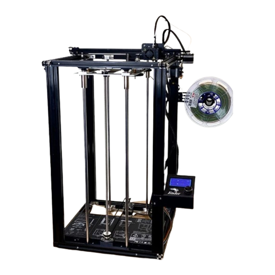
Ender 5 Machine Overview
Identify Key Components
Identify vertical extrusions, smooth rods, and lead screw.
Step 1: Inventory the Kit Contents
Frame and Rod Components
Four vertical extrusions and rear lead screw/rods.
Front Rods and Hardware
Front lead screw/rods and flange bearings/screws.
Wire Extensions
Extensions for heated bed, nozzle heater, thermistors, and fans.
Drive and Mounting Parts
Stepper motor extensions, pulleys, belts, and tensioner kit.
Brackets and Plates
Rod mounting brackets and aluminum carriage plate.
Step 2: Ender 5 Non-Pro and Pro Differences
Z-Axis Lead Screw Variations
Differences in Z-axis lead screw between Non-Pro and Pro models.
Step 3: Disassemble the Ender 5
Disconnect Power and Remove Bed
Disconnect power cable and remove bed print surface, wheels, springs, screws.
Loosen Rod Mounting Screws
Loosen smooth rod mounting screws from top and bottom supports.
Remove Lead Screw Nut
Remove M3 screws and nuts from the lead screw brass nut.
Remove Smooth Rods
Remove the two smooth rods from the printer frame.
Remove Carriage Plate
Remove the black carriage plate from the Z-axis assembly.
Remove Flange Bearings
Remove and keep the left/ride flange bearings for reuse.
Lead Screw Coupler Adjustment
Loosen lead screw set screw and remove lead screw from coupler.
Remove Top Front Frame Member
Remove top front frame member and associated screws.
Step 4: Assemble the Base Plate
Gather Base Plate Components
Gather original flange bearings, screws, and kit aluminum base plate.
Clean and Lubricate Parts
Clean and lubricate rods, lead screw, and bearings with grease.
Install Bearings and Screws
Insert bearings into corners and attach screws loosely.
Prepare Brass Nuts
Locate two brass nuts and eight screws for the base plate.
Attach Brass Nuts to Plate
Mount brass nuts from underside of plate with cylinder portion pointing down.
Step 5: Assemble Front Rod Support Brackets
Top Rod Mounting Bracket
Gather parts and affix M5 lock washers to M5x20 screws for the top bracket.
Mount Top Rod Bracket
Insert M5x20 screws and attach M5 t-slot nuts to the top rod mounting bracket.
Bottom Rod Mounting Bracket Prep
Gather parts for the bottom bracket including M4x16 screws and KFL08 bearing.
Attach Bottom Rod Bracket Hardware
Insert M4x16 screws into flange bearing holes and attach to bottom rod mounting bracket.
Step 6: Assemble the Belt Tensioner
Gather Belt Tensioner Parts
Collect parts for the belt tensioner, including bracket, bearings, and screws.
Assemble Tensioner Bracket
Attach M5 lock washers and screws to the tensioner bracket.
Attach Bearings to Support
Ensure flange bearings are on the outer edge of the printed bearing support.
Secure Tensioner Bearing Support
Attach M5 flat washer and screw to the bearing support.
Final Tensioner Assembly
Screw M5x40 hex cap screw into tensioner bracket securely but without overtightening.
Step 7: Mount Rod Brackets to Frame
Position Top Rod Mounting Bracket
Temporarily attach top frame member and position rod bracket using t-slot nuts.
Attach Bottom Rod Bracket
Attach the bottom rod mounting bracket to the bottom frame member.
Position Carriage Plate
Position carriage plate over power supply, aligning bearings with rod brackets.
Insert Front Smooth Rods
Insert front 10mm smooth rods through bearings into the rod mounting bracket.
Insert Rear Smooth Rods
Insert rear 10mm smooth rods through rear bearings into rod support mounts.
Tighten Rear Rod Support Screws
Tighten bottom rear rod support screws first, then top rear rod support screws.
Insert Rods into Bottom Bracket
Insert the 10mm smooth rods into the bottom mounting bracket.
Install Rear Lead Screw and Coupler
Insert rear lead screw, place pulley, and connect to Z motor coupler.
Loosen KFL08 Bearing Set Screw
Loosen the KFL08 flange bearing set screw to allow lead screw insertion.
Position Belt on Bearings
Position the closed loop belt over the Z motor coupler and front flange bearing.
Insert Lead Screw and Pulley
Insert lead screw through brass nut, place pulley, and into KFL08 bearing.
Attach Top Front Frame Member
Attach top front frame member, position rods, center bracket, tighten screws.
Tighten M5x20 Screws
Insert and tighten M5x20 hex cap screws as needed.
Tighten Inner M4 Screws
Insert and tighten inner M4 button head screws as needed.
Level Carriage Plate
Move carriage to top, adjust front/rear height for even positioning.
Position Tensioner Unit
Position tensioner unit between Z motor bracket and left rear rod bracket; set screws loose.
Loop Belt Over Bearing
Loop the drive belt over the bearing for tensioning.
Align Belt and Pulleys
Check belt and pulley alignment for even height and no angle.
Tighten Tensioner Screws
Hold tension on pulley and tighten M5 hex cap screws on the tensioner.
Final Carriage Plate Check
Check carriage plate distance front/back and move X axis for measuring.
Tighten Pulley Set Screws
Once carriage plate is even, tighten the pulley set screws.
Step 8: Wire Extensions
Connect Wire Extensions
Attach wire extensions to control board and wiring harness, ensuring they are labeled.
Slicer Settings
Cura Configuration Overview
Focus on Cura for larger bed printing with updated firmware.
Firmware and G-code Commands
Discusses Marlin firmware, M211 command for software endstops.
Manage Printer Profiles
Select and manage printer profiles within Cura.
Machine Settings and G-Code
Adjust X, Y, Z size and review Start G-Code.
Configure Printer Dimensions
Set X, Y, Z dimensions (400x400x500mm) and printhead limits in Cura.
Disable Software Endstops
Ensure M211 S0 is in Start G-code to disable software endstops.
Need help?
Do you have a question about the XL and is the answer not in the manual?
Questions and answers