Advertisement
Quick Links
HIGH VOLTAGE KIT
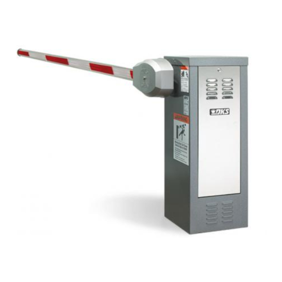
This kit will alter the input AC voltage on a DoorKing 115 VAC: 6500, 6300, 9000, 9150 or 1600 Series operators to
208, 230, 460 or 575 VAC.
Choose and follow the installation and wiring instructions for YOUR specific operator on the next 4 pages.
AC Input Power Wire Limitations
The table below shows the AC input power wire size and maximum distance wire run limitations. If AC power wire run is greater than the maximum distance
shown, it is recommended that a service feeder be installed. When large gauge wire is used, a separate junction box must be installed for the operator
connection. An external power disconnect switch is required. Check local building codes before installation.
Never run HIGH voltage rated wire
insulation in the same conduit as
LOW voltage rated wire insulation.
Keep them in separate conduits.
Step-Down Transformer Optional Voltage Wiring
Choose desired input voltage plug and connect accordingly AFTER step-down transformer has been mounted in the operator.
208 VAC Input
208 VAC
1-Phase/
3-Phase
Power Wire
Use only two legs of the
External Power
incoming 3-phase power
Disconnect
Switch
and terminate the 3rd leg.
Required
230 VAC Input
230 VAC
1-Phase/
3-Phase
Power Wire
Use only two legs of the
External Power
incoming 3-phase power
Disconnect
Switch
and terminate the 3rd leg.
Required
460 VAC Input
460 VAC
3-Phase
Power Wire
Use only two legs of the
External Power
Disconnect
incoming 3-phase power
Switch
and terminate the 3rd leg.
Required
575 VAC Input
575 VAC
3-Phase
Power Wire
Use only two legs of the
External Power
incoming 3-phase power
Disconnect
Switch
and terminate the 3rd leg.
Required
2600-267-G-6-16
DO NOT USE THIS KIT ON ANY OTHER OPERATOR.
Primary/Single Operator
Input Voltage
Motor
208/230 VAC
1/2 HP
2.8 Amps
460 VAC
1/2 HP
1.4 Amps
575 VAC
1/2 HP
1.0 Amp
208/230 VAC
1 HP
5.0 Amps
460 VAC
1 HP
2.5 Amps
575 VAC
1 HP
2.0 Amps
1st Leg
2nd Leg
3rd Leg
1st Leg
2nd Leg
3rd Leg
1st Leg
2nd Leg
3rd Leg
1st Leg
2nd Leg
3rd Leg
Copyright 2016 DoorKing, Inc. All rights reserved.
Wire Size / Max Distance in Feet
12 AWG 10 AWG
Amps
685
1100
2875
4600
2875
4600
380
650
1500
2500
1500
2500
1st Leg
2nd Leg
208 V
Plug
Input Voltage Plug
1st Leg
2nd Leg
230 V
Plug
Input Voltage Plug
1st Leg
2nd Leg
460 V
Plug
Input Voltage Plug
1st Leg
2nd Leg
575 V
Plug
Input Voltage Plug
8 AWG
6 AWG
1830
2750
Note: Wire run distances are based on
7665
11,500
NEC guidelines for copper wire allowing
7665
11,500
a maximum 3% voltage drop on the line.
1100
1600
The calculated distance was then further
4000
6500
reduced by 10% to allow for other loses
4000
6500
in the system.
208 V Plug
X
Configuration
Transformer
Plug
Black/White
230 V Plug
X
Configuration
Brown
Transformer
Plug
460 V Plug
X
Configuration
Transformer
Plug
575 V Plug
X
Configuration
Transformer
Plug
Inglewood, California 90301
DoorKing Part Number
2600-266
Transformer Plug
Configuration
White
X
Open
Black
Blue
To operator
115 VAC
power
terminal.
White
Black
Green
To operator
Chassis
Ground.
120 S. Glasgow Avenue
U.S.A.
Advertisement

Related Manuals for DoorKing Series 6300


Summarization of Contents
High Voltage Kit Introduction and Guidelines
AC Input Power Wire Limitations
Details AC input power wire size and maximum distance limitations for safe operation.
Step-Down Transformer Optional Voltage Wiring
Instructions for connecting the step-down transformer to various input AC voltages.
Model 6500 Transformer Installation
Model 6500 Transformer Mounting
Instructions for mounting the step-down transformer on the Model 6500 operator.
Model 6500 Transformer Wiring
Guidance on wiring the step-down transformer for desired input voltage on Model 6500.
Model 6500 Important Installation Notes
Key considerations for Model 6500, including dual gates, heaters, and safety warnings.
Model 6300 & 9000 Transformer Installation
Model 6300 Transformer Mounting and Wiring
Steps for mounting and wiring the transformer on the Model 6300 operator.
Model 6300 Important Installation Notes
Key considerations for Model 6300, including dual gates, heaters, and safety warnings.
Model 9000 Transformer Mounting and Wiring
Steps for mounting and wiring the transformer on the Model 9000 operator.
Model 9000 Important Installation Notes
Key considerations for Model 9000, including dual gates, heaters, and safety warnings.
Model 9150 Transformer Installation
Model 9150 Transformer Mounting
Instructions for mounting the step-down transformer on the Model 9150 operator.
Model 9150 Transformer Wiring
Guidance on wiring the step-down transformer for desired input voltage on Model 9150.
Model 9150 Important Installation Notes
Key considerations for Model 9150, including dual gates, heaters, and safety warnings.
Model 1600 Series Transformer Installation
Model 1600 Series Transformer Mounting
Steps for mounting the transformer on the Model 1600 Series operator.
Model 1600 Series Transformer Wiring
Guidance on wiring the step-down transformer for desired input voltage on Model 1600 Series.
Model 1600 Series Important Installation Notes
Key considerations for Model 1600 Series, including dual gates, heaters, and safety warnings.
Need help?
Do you have a question about the Series 6300 and is the answer not in the manual?
Questions and answers