
Related Manuals for WAGO 4AO 4-20mA


Summarization of Contents
Notes about this Documentation
1.1 Validity of this Documentation
Specifies the applicability of this documentation to the 750-555 (4AO 4-20mA) I/O module.
1.2 Copyright
Outlines copyright protection for the manual and restrictions on its use.
1.3 Symbols
Defines safety symbols like DANGER, WARNING, CAUTION, and NOTICE for hazard identification.
1.4 Number Notation
Explains the notation used for decimal, hexadecimal, and binary numbers in the document.
1.5 Font Conventions
Details font usage for paths, menus, inputs, buttons, and keys for clarity.
Important Notes
2.1 Legal Bases
Covers WAGO's rights for alterations, patents, and mentions third-party products.
2.2 Safety Advice (Precautions)
Provides critical safety precautions for installing and operating the device to prevent injury and damage.
2.1.4 Technical Condition of Specified Devices
Details device conditions, non-serviceable parts, and actions that void liability.
Device Description
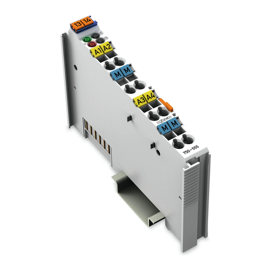
3.1 View
Illustrates the physical layout of the I/O module and its components.
3.2 Connectors
Describes data contacts, power jumper contacts, and CAGE CLAMP® connectors for wiring and data transfer.
3.3 Display Elements
Explains the function of the LEDs indicating operational status and errors.
3.4 Operating Elements
States that the I/O module 750-555 has no operating elements.
3.5 Schematic Diagram
Presents the electrical schematic diagram for the 750-555 module.
3.6 Technical Data
Provides detailed technical specifications for the device, power supply, communication, and environmental conditions.
3.7 Approvals
Lists the various certifications and approvals granted to the 750-555 I/O modules.
3.8 Standards and Guidelines
Outlines the EMC and marine application standards the modules comply with.
Process Image
Process Data Mapping
Details the mapping of output values to current signals and status bits.
Mounting
5.1 Mounting Sequence
Describes the step-by-step process for snapping modules onto the carrier rail.
5.2 Inserting and Removing Devices
Details the procedure for safely inserting and removing I/O modules from the system.
Connect Devices
6.1 Connecting a Conductor to the CAGE CLAMP®
Explains the correct method for connecting conductors to CAGE CLAMP® terminals.
6.2 Connection Example
Illustrates a typical wiring example for connecting devices to the I/O module.
Use in Hazardous Environments
7.1 Marking Configuration Examples
Shows examples of marking configurations for ATEX, IECEx, and NEC/CEC standards.
7.2 Installation Regulations
Outlines general and specific installation rules for hazardous area operation.
7.2.1 Special Notes Regarding Explosion Protection
Provides critical warnings and requirements for explosion protection in hazardous zones.
7.2.2 Special Notes Regarding ANSI/ISA Ex
Lists additional requirements for ANSI/ISA Ex certification, including use in Class I, Division 2.
Need help?
Do you have a question about the 4AO 4-20mA and is the answer not in the manual?
Questions and answers