
Related Manuals for Stryker Prime TC 1450


Summary of Contents for Stryker Prime TC 1450
- Page 1 Prime TC™ 1450/1460 Transport Chair Operations/Maintenance Manual 2014/07 D.1 1460-009-001 REV D www.stryker.com...
- Page 2 sample text...
- Page 3 Operating instructions General warning Caution Warning; crushing of hands No pushing Model Serial number CE mark Manufacturer Date of manufacture Safe working load Lubricate Fragile, handle with care Keep dry This way up Do not stack www.stryker.com 1460-009-001 REV D...
- Page 4 sample text...
-
Page 5: Table Of Contents
Quick reference replacement parts ......................36 Service ..............................37 Seat back removal ..........................37 Seat back replacement........................38 Chart holder replacement ........................39 Seat replacement ..........................40 Flip-up armrest replacement ........................ 41 Front caster wheel replacement ......................42 www.stryker.com 1460-009-001 REV D... - Page 6 Leg rest latch assembly, patient left - 1460-166-040 ..................89 Leg rest latch assembly, patient right - 1460-166-080 ..................90 No leg rest - 1460-066-100 ........................91 Warranty ............................... 92 Warranty exclusion and damage limitations..................... 92 To obtain parts and service........................92 Return authorization........................... 92 1460-009-001 REV D www.stryker.com...
- Page 7 Table of Contents Damaged product ..........................92 International warranty clause ....................... 93 www.stryker.com 1460-009-001 REV D...
-
Page 8: Warning/Caution/Note Definition
Note: Provides special information to make maintenance easier or important instructions clearer. 1460-009-001 REV D www.stryker.com... -
Page 9: Introduction
Introduction This manual is designed to assist you with the operation or maintenance of the Stryker Model 1450 and Model 1460 Prime TC™ (Transport Chair). Read this manual thoroughly before operating or maintaining this product. Establish methods and procedures for educating and training staff on the safe operation or maintenance of this product. -
Page 10: Specifications
First Chair Length 39.8 in. 101.0 cm 39.8 in. 101.0 cm First Chair Length with 33.4 in. 84.8 cm Footrest Stowed Length added by each 19.5 in. 49.5 cm 20.5 in. 52.1 cm additional nested chair 1460-009-001 REV D www.stryker.com... - Page 11 Relative Humidity 30 % 30 % 1060 hPa 1060 hPa Atmospheric Pressure 700 hPa 500 hPa Specifications listed are approximate and may vary slightly from product to product. Stryker reserves the right to change specifications without notice. www.stryker.com 1460-009-001 REV D...
-
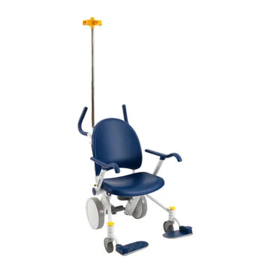
Page 12: Product Illustration - Fixed Footrest (Model 1450)
Oxygen bottle holder bottom, optional Flip-up armrest Oxygen bottle holder top, optional Flip-up footrest Rear wheel Foley bag hook, optional Seat Footrest assembly, fixed Seat back Footrest lever Leg rest, optional Front caster Lap belt, optional Handles 1460-009-001 REV D www.stryker.com... -
Page 13: Product Illustration - Swing-Away Footrest (Model 1460)
Oxygen bottle holder bottom, optional Flip-up armrest Oxygen bottle holder top, optional Rear wheel Flip-up footrest Foley bag hook, optional Seat Footrest assembly, swing-away Seat back Footrest lever Swing-away footrest release Front caster Leg rest, optional Handles Lap belt, optional www.stryker.com 1460-009-001 REV D... -
Page 14: Contact Information
Stryker Medical 3800 E. Centre Avenue Portage, MI 49002 Have the serial number (A) of your Stryker product available when calling Stryker Customer Service or Technical Support. Include the serial number in all written communication. Serial number location EC REP S tryke r Fra nce S .A.S . -
Page 15: Summary Of Safety Precautions
Only attach foley bags to the optional foley bag hook. • Always properly secure the IV bags to the hooks on the optional IV pole or the foley bags to the optional foley bag hook before moving the product. www.stryker.com 1460-009-001 REV D... - Page 16 Failure to follow these cleaning instructions may void your warranty. 1460-009-001 REV D www.stryker.com...
-
Page 17: Pinch Points
Summary of safety precautions Pinch points Figure 4: Pinch points www.stryker.com 1460-009-001 REV D... -
Page 18: Setup
6. Return the swing-away footrest to the use position and make sure that the footrest locks in place (Model 1460). 7. Make sure that any optional accessories are installed and operate as described in the operation instructions. 1460-009-001 REV D www.stryker.com... -
Page 19: Operation
To release the brake, push down on the go pedal (B). Note: The rear wheel locking brake mechanism prevents rear wheel rotation only. The brake mechanism does not prevent the chair from sliding on the floor surface. Figure 5: Brake pedal and go pedal www.stryker.com 1460-009-001 REV D... -
Page 20: Transferring An Occupant
(Figure 6 on page 16). Position the occupant’s feet fully on the footrests. Put the flip-up armrests down and make sure that the occupant’s arms are fully positioned on the armrests. Figure 6: Flip-up footrest lever 1460-009-001 REV D www.stryker.com... -
Page 21: Removing An Occupant
Push down on the brake pedal to apply the brake. Push on the product to make sure that the brake is working. Make sure that the occupant’s feet are clear of the flip-up footrests and that the flip-up footrests have moved to the stowed position. Remove the occupant from the product following facility protocol. www.stryker.com 1460-009-001 REV D... -
Page 22: Positioning The Flip-Up Footrest
Make sure that the occupant’s feet are clear of the flip-up footrests (A). Using your foot, lower the flip-up footrest to the transport position by lifting up on the footrest lever (B). Position the occupant’s feet fully on the flip-up footrests (C). Figure 7: Flip-up footrest transport position 1460-009-001 REV D www.stryker.com... -
Page 23: Stowing The Flip-Up Footrest
To stow the flip-up footrest: Make sure that the occupant’s feet are clear of the flip-up footrests. Make sure that the flip-up footrests raise to the stowed position (A) (Figure 8 on page 19). Figure 8: Flip-up footrests stowed position www.stryker.com 1460-009-001 REV D... -
Page 24: Positioning The Swing-Away Footrest (Model 1460)
Make sure that the occupant’s feet are clear of the flip-up footrest (A). Using your foot, lower the flip-up footrest to the transport position by lifting up on the footrest lever (C). Position the occupant’s feet fully on the flip-up footrests (A). Figure 9: Swing-away footrest use position 1460-009-001 REV D www.stryker.com... -
Page 25: Stowing The Swing-Away Footrest (Model 1460)
Clear the path of the swing-away footrests. Using your foot, press the yellow swing-away footrest release button (D) on the top of the swing-away footrest and put the swing-away footrest in the stowed position (B). Figure 10: Swing-away footrest stowed position www.stryker.com 1460-009-001 REV D... -
Page 26: Raising Or Lowering The Flip-Up Armrests
Lower the flip-up armrest into the forward position until the armrest latches securely (Figure 11 on page 22). Figure 11: Pinch points when raising armrests and lowering armrests 1460-009-001 REV D www.stryker.com... -
Page 27: Storing Records In The Chart Holder
23). The chart holder holds a 3-inch, three-ring binder. Note: The sides of the chart holder are open for ease of cleaning. Do not put loose paperwork in the chart holder. Figure 12: Storing records in the chart holder www.stryker.com 1460-009-001 REV D... -
Page 28: Transporting An Occupant
Note: When attempting to operate a heavily loaded product, the startup movement and mobility may be difficult. To transport an occupant: Face the back of the chair. Grip the push handles with two hands. Apply the go pedal. 1460-009-001 REV D www.stryker.com... -
Page 29: Securing An Oxygen Bottle In The Oxygen Bottle Holder
Lower the yellow arm (A) on the optional oxygen bottle holder top (C) to secure the oxygen bottle. Verify that the top latch is closed properly before moving the chair. Figure 13: Optional oxygen bottle holder top positions www.stryker.com 1460-009-001 REV D... -
Page 30: Accessories
Accessories These accessories may be available for use with your product.Confirm availability for your configuration or region.Call Stryker Customer Service: 1-800-327-0770. Name Number Securing a foley bag to the foley bag hook on page 27 1460-101-150 1460-035-000 Securing an IV bag to the IV pole on page 28... -
Page 31: Securing A Foley Bag To The Foley Bag Hook
To secure a foley bag to the optional foley bag hook, place the hook of the foley bag on the optional foley bag hook (Figure 14 on page 27). Make sure that you have securely attached the foley bag. Figure 14: Foley bag hook location www.stryker.com 1460-009-001 REV D... -
Page 32: Securing An Iv Bag To The Iv Pole
Pull on the optional IV pole (A) to make sure that it is secure (Figure 15 on page 28). Place the IV bags onto the hooks and make sure that the bags are secure. Figure 15: IV pole 1460-009-001 REV D www.stryker.com... -
Page 33: Fastening The Lap Belt
Inspect the lap belt at least once a month (more frequently if used more often). Check for a bent or broken receiver or buckle latch, or torn or frayed straps. Immediately replace any worn or inoperable lap belt strap. Figure 16: Open the lap belt www.stryker.com 1460-009-001 REV D... - Page 34 Accessories Fastening the lap belt (Continued) Figure 17: Close the lap belt 1460-009-001 REV D www.stryker.com...
-
Page 35: Positioning The Leg Rest
Pull up on the leg rest (B) until it clicks and locks in the use position. Push down on the leg rest to make sure that it is secure. Position the occupant’s leg on the leg rest (B). Figure 18: Leg rest use position www.stryker.com 1460-009-001 REV D... -
Page 36: Stowing The Leg Rest
Push the leg rest (B) toward the back of the chair until it clicks. Push the leg rest (B) toward the back of the chair to make sure that it is secure. Figure 19: Leg rest stowed position 1460-009-001 REV D www.stryker.com... -
Page 37: Labels
M ousse de polyuréthane Polyurethane Foam FLAMMABILITY REQUIREMENTS OF CALIFORNIA BUREAU OF HOME FURNISHINGS TECHNICAL BULLETIN NO.1 17. CARE SHOULD M ade in U.S.A. / Fabriqué aux Etats-Unis BE EXERCISED NEAR OPEN FLAME OR WITH BURNING CIGARETTES. www.stryker.com 1460-009-001 REV D... -
Page 38: Cleaning
Failure to follow these cleaning instructions may void your warranty. 1460-009-001 REV D www.stryker.com... -
Page 39: Preventive Maintenance
Preventive maintenance At a minimum, check all items listed during annual preventive maintenance for all Stryker Medical products. You may need to perform preventive maintenance checks more frequently based on your level of product usage. Service only by qualified personnel. -
Page 40: Quick Reference Replacement Parts
Quick reference replacement parts These parts are currently available for purchase. Call Stryker Customer Service: 1-800-327 -0770 for availability and pricing. Name Number Flip-up armrest assembly, patient left 1460-700-001 Flip-up armrest assembly, patient right 1460-700-002 Foley bag hook 1460-101-150 Front caster assembly... -
Page 41: Service
70 ± 10 in-lb. Verify proper operation before returning the product to service. Torque item A to 70 ± 10 in-lb Torque item A to 70 ± 10 in-lb Figure 20: Seat back removal www.stryker.com 1460-009-001 REV D... -
Page 42: Seat Back Replacement
(Figure 21 on page 38). Using a 3/8” drive torque wrench, torque the screws to 70 ± 10 in-lb. Apply the supplied Stryker label (D) in the appropriate color. Verify proper operation before returning the product to service. Torque item A to 70 ±... -
Page 43: Chart Holder Replacement
Reverse steps 2-4 to install the supplied chart holder. Verify proper operation before returning the product to service. Torque item A to 25 ± 5 in-lb Figure 22: Chart holder replacement www.stryker.com 1460-009-001 REV D... -
Page 44: Seat Replacement
ONLY M anufactured For STRYKER M EDICAL Ce t a rticle contie nt de s 3800 E. Centre Avenue MATERIAUX NEUFS... -
Page 45: Flip-Up Armrest Replacement
Using a 5/16” hex wrench, install the supplied hard stop pin (removed in step 2). Using a 3/8” drive torque wrench, torque the hard stop pin to 33 ± 7 ft-lb. Verify proper operation before returning the product to service. Torque item A to 33 ± 7 ft-lb Figure 24: Flip-up armrest replacement www.stryker.com 1460-009-001 REV D... -
Page 46: Front Caster Wheel Replacement
(Figure 25 on page 42). Properly align the nut in the caster fork (E) during reinstallation. Verify proper operation before returning the product to service. to 70 ± 10 in-lb Figure 25: Front caster wheel replacement 1460-009-001 REV D www.stryker.com... -
Page 47: Front Caster Assembly Replacement
Note: The axle barrel nut (B) head is keyed (Figure 26 on page 43). Properly align the nut in the caster fork (E). Verify proper operation before returning the product to service. to 70 ± 10 in-lb Figure 26: Front caster assembly replacement www.stryker.com 1460-009-001 REV D... -
Page 48: Swing-Away Footrest Replacement (Model 1460)
Reverse steps 3-8 to install the supplied swing-away footrest assembly. Using a 3/8” drive torque wrench, torque the caster fork bolt (D) to 75 ± 5 ft-lb before installing the caster to the fork. 10. Verify proper operation before returning the product to service. Figure 27: Swing-away footrest replacement 1460-009-001 REV D www.stryker.com... -
Page 49: Rear Wheel Replacement
Reverse steps 2-5 to install the supplied rear wheel. Using a 3/8” drive torque wrench, torque the rear wheel center nut (B) to 25 ± 2 ft-lb. Verify proper operation before returning the product to service. Figure 28: Rear wheel replacement www.stryker.com 1460-009-001 REV D... -
Page 50: Pedal Replacement
Note: Note the orientation of the brake cam assembly (P). Make sure that the tab faces the front of the chair (Figure 29 on page 47). 16. Verify proper operation before returning the product to service. 1460-009-001 REV D www.stryker.com... - Page 51 Service Pedal replacement (Continued) Figure 29: Pedal replacement www.stryker.com 1460-009-001 REV D...
-
Page 52: Brake Finger Assembly Replacement
(Figure 29 on page 47), make sure that the tab faces the front of the chair. 10. Verify proper operation before returning the product to service. to 70 ± 10 in-lb Figure 30: Brake finger assembly replacement 1460-009-001 REV D www.stryker.com... -
Page 53: Iv Pole Removal
11. Using a 3/16” hex wrench and the supplied flat head cap screws (0001-210-000) (A), install the supplied lower IV clamp front and back onto the IV pole. Using a 3/8” drive torque wrench (ft-lb), torque the screws to 13 ± 3 ft-lb. www.stryker.com 1460-009-001 REV D... - Page 54 Note: Align the lower IV clamp, so the clamp is flush with the bottom of the IV pole. 12. Reinstall the seat back (Seat back removal on page 37). 13. Verify proper operation before returning the product to service. Torque item A to 13 ± 3 ft-lb Figure 31: IV pole replacement 1460-009-001 REV D www.stryker.com...
-
Page 55: Iv Pole Topper Replacement
IV pole. Using a 3/8” drive torque wrench, torque the screw to 25 ± 5 in-lb. Verify proper operation before returning the product to service. Torque item A to 25 ± 5 in-lb Figure 32: IV pole topper replacement www.stryker.com 1460-009-001 REV D... -
Page 56: Lap Belt Assembly Installation
(Figure 34 on page 53). Using a 3/8” drive torque wrench and a 3/16” hex bit, torque the screw to 70 ± 10 in-lbs. Verify proper operation before returning the product to service. Figure 33: Lap belt bracket tabs 1460-009-001 REV D www.stryker.com... - Page 57 Service Lap belt assembly installation (Continued) Figure 34: Lap belt bracket installation www.stryker.com 1460-009-001 REV D...
-
Page 58: Lap Belt Removal
With one hand, grasp the looped end of the supplied belt and with the other hand, grasp the bracket. Squeeze the looped end of the belt and manipulate the belt through the slot in the bracket. Verify proper operation before returning the product to service. 1460-009-001 REV D www.stryker.com... -
Page 59: Leg Rest Installation
Using a 3/8” drive torque wrench, torque the screws to 70 ± 10 in-lb. Verify proper operation before returning the product to service. Torque item A to 70 ± 10 in-lb Figure 36: Leg rest weldment www.stryker.com 1460-009-001 REV D... - Page 60 Service Leg rest installation (Continued) Figure 37: Leg rest components 1460-009-001 REV D www.stryker.com...
-
Page 61: Leg Rest Leg Replacement
Install the washers (P) on the bushing (M) before putting them on the leg rest assembly. Use a 3/8” drive torque wrench to torque the screws to 70± 10 in-lb. 10. Verify proper operation before returning the product to service. www.stryker.com 1460-009-001 REV D... -
Page 62: Leg Rest Adjustment
Push down on the brake pedal to apply the brake. Push on the product to make sure that the brake is working. Using a 7/16" combination wrench, tighten or loosen the nylock hex nut (J) in quarter turn increments. (Figure 37 on page 56). Verify proper operation before returning the product to service. 1460-009-001 REV D www.stryker.com... -
Page 63: Fixed Frame And Footrest Assembly (Model 1450)
Item Part No. Part Name 0003-333-000 Hex head cap screw 1450-001-010 Frame weldment, fixed 1450-015 -050 Fixed footrest assembly, left (model 1450) on page 60 1450-015 -070 Fixed footrest assembly, right (model 1450) on page 61 www.stryker.com 1460-009-001 REV D... -
Page 64: Fixed Footrest Assembly, Left (Model 1450)
Footrest pan pivot cover, left 1460-015- 024 Footrest end cap 1460-015- 027 Footrest pan torsion spring, left 1460-015- 028 Footrest slotted spring holder, left 1460-015- 029 Footrest fixed spring housing, left 1460-015- 120 Footrest pan insert assembly, left 1460-009-001 REV D www.stryker.com... -
Page 65: Fixed Footrest Assembly, Right (Model 1450)
Footrest end cap 1460-015 -043 Footrest pan pivot cover, right 1460-015 -047 Footrest pan torsion spring, right 1460-015 -048 Footrest slotted spring holder, right 1460-015 -049 Footrest fixed spring housing, right 1460-015 -140 Footrest pan insert assembly, right www.stryker.com 1460-009-001 REV D... -
Page 66: Swing-Away Frame And Footrest Assembly
Part No. Part Name 0003-333-000 Hex head cap screw 1460-001- 010 Frame weldment, swing-away 1460-015- 050 Swing-away footrest assembly, left (model 1460) on page 63 1460-015- 070 Swing-away footrest assembly, right (model 1460) on page 64 1460-009-001 REV D www.stryker.com... -
Page 67: Swing-Away Footrest Assembly, Left (Model 1460)
Footrest end cap 1460-015 -027 Footrest pan torsion spring, left 1460-015 -028 Footrest slotted spring holder, left 1460-015 -029 Footrest fixed spring housing, left 1460-015 -055 Weldment, swing-away, left 1460-015 -120 Footrest pan insert assembly, left www.stryker.com 1460-009-001 REV D... -
Page 68: Swing-Away Footrest Assembly, Right (Model 1460)
Footrest pan pivot cover, right 1460-015- 047 Footrest pan torsion spring, right 1460-015- 048 Footrest slotted spring holder, right 1460-015- 049 Footrest fixed spring housing, right 1460-015- 075 Weldment, swing-away, right 1460-015- 140 Footrest pan insert assembly, right 1460-009-001 REV D www.stryker.com... -
Page 69: Common Components
Common components 1460-016-010 Rev C (Reference Only) Torque item A 70 ± 10 in-lb Torque item A 70 ± 10 in-lb www.stryker.com 1460-009-001 REV D... - Page 70 Common components Sea t Back Plaque Colors 1460-013-024 Dark Lilac 1460-013-025 Navy 1460-013-026 Powder Blue 1460-013-027 Cool Gray 1460-013-028 Y ellow 1460-013-029 Torque item B 70 ± 10 in-lb Torque item B 70 ± 10 in-lb 1460-009-001 REV D www.stryker.com...
- Page 71 Frame caster tube plug 1460-001-007 Frame handle cover 1460-001-041 Frame upright cap 1460-001-042 Anti-tip wheel 1460-003-043 Anti-tip wheel spacer nut 1460-003-000 Brake assembly on page 69 1460-003-007 Label, brake/toggle hole cover 1460-003-080 Swivel caster assembly on page 73 www.stryker.com 1460-009-001 REV D...
- Page 72 Common components Item Part No. Part Name 1460-006-010 Rear wheel assembly 1460-006-014 Rear wheel outer cap 1460-011- 000 Armrest assembly on page 75 1460-013- 033 Seat back screw adapter 1460-013- 040 Seat back/bolster assembly 1460-050-005 Chart holder 1460-009-001 REV D www.stryker.com...
-
Page 73: Brake Assembly
Brake assembly 1460-003-000 Rev B (Reference Only) Torque item A to 25 ± in-lb Torque item B 70 ± 10 in-lb www.stryker.com 1460-009-001 REV D... - Page 74 Brake assembly 70 ± 10 in-lb 1460-009-001 REV D www.stryker.com...
- Page 75 Brake shaft cover, left 1460-003-025 Brake disc assembly 1460-003-029 Brake cross bar collar 1460-003-030 Brake finger holder assembly 1460-003-036 Brake finger spacer nut 1460-003-040 Brake cam assembly 1460-003-044 Brake shaft cover, right 1460-003-048 Brake cam spring www.stryker.com 1460-009-001 REV D...
- Page 76 Brake assembly Item Part No. Part Name 1460-003-049 Brake cam spring pad 1460-003-050 Toggle link assembly 1460-003-057 Toggle link rod 1460-003-065 Rear wheel shaft assembly 1460-009-001 REV D www.stryker.com...
-
Page 77: Swivel Caster Assembly
Swivel caster assembly 1460-003-080 Rev B (Reference Only) to 70 ± 10 in-lb Item Part No. Part Name 1460-003-085 Wheel assembly 1460-003-086 Axle barrel nut 1460-003-087 Axle cap 1460-003-088 Axle screw 1460-003-089 Caster horn assembly www.stryker.com 1460-009-001 REV D... -
Page 78: Non-Padded Seat
Non-padded seat 1460-013-000 Rev A (Reference Only) Torque item A 70 ± 10 in-lb Item Part No. Part Name 0004-671- 000 Flange button head cap screw 1460-013- 020 Seat pan, non-padded 1460-009-001 REV D www.stryker.com... -
Page 79: Armrest Assembly
Torque item A to 33 ± ft-lb Torque item A to 33 ± ft-lb Item Part No. Part Name 1460-011-008 Armrest hard stop pin 1460-011-010 Armrest assembly, right on page 76 1460-011-020 Armrest assembly, left on page 77 www.stryker.com 1460-009-001 REV D... -
Page 80: Armrest Assembly, Right
1460-011-010 Rev A (Reference Only) Item Part No. Part Name 0038-133- 000 Compression wire 0785-045-450 Knob 1460-001- 003 Label, Stryker manufacturing 1460-011- 006 Armrest lock pin sleeve 1460-011- 007 Armrest pin lock 1460-011- 009 Armrest pivot flange bearing 1460-011- 012 Armrest pivot cap... -
Page 81: Armrest Assembly, Left
Armrest assembly, left 1460-011-020 Rev A (Reference Only) Item Part No. Part Name 0038-133 -000 Compression wire 0785-045-450 Knob 1460-001-003 Label, Stryker manufacturing 1460-011-006 Armrest lock pin sleeve 1460-011-007 Armrest pin lock 1460-011-009 Armrest pivot flange bearing 1460-011-012 Armrest pivot cap 1460-011-125 Armrest weldment, left www.stryker.com... -
Page 82: No Oxygen Bottle Holder
No oxygen bottle holder 1460-045-100 Rev A (Reference Only) Item Part No. Part Name 1460-045-007 Oxygen bottle holder hole plug 1460-066-013 Leg rest push-in clip 1460-009-001 REV D www.stryker.com... -
Page 83: Oxygen Bottle Holder
Torque item B to 13 ± ft-lb Item Part No. Part Name 0004-662-000 Socket head cap screw 0007-074-000 Truss head machine screw 1460-045-010 Oxygen bottle holder, bottom 1460-045-020 Oxygen holder top assembly 1460-045-023 Oxygen holder top mount www.stryker.com 1460-009-001 REV D... -
Page 84: Padded Seat - 1460-013-050
Torque item A accordance with law. ONLY M anufactured For STRYKER M EDICAL Cet a rticle contie nt de s to 70 ± 10 in-lb 3800 E. Centre Avenue MATERIAUX NEUFS... -
Page 85: No Iv Pole - 1460-035-100
No IV pole - 1460-035-100 Rev A (Reference Only) Item Part No. Part Name 1460-035-007 IV clamp hole plug www.stryker.com 1460-009-001 REV D... -
Page 86: Pole - 1460-035-000
Part No. Part Name 0001-210- 000 Flat head cap screw 0004-672-000 Socket head cap screw 0018-045-000 Tube connector 0026-349-000 Clevis pin 0037-225- 000 Tube plug 1460-035-021 IV pole 1460-035-022 IV clamp, front 1460-035-023 IV clamp, back 1460-009-001 REV D www.stryker.com... -
Page 87: Lap Belt - 1460-013-100
Torque item A to 70 ± 10 in-lb Torque item A to 70 ± 10 in-lb Item Part No. Part Name 0004-671-000 Flange button head cap screw 1460-013 -101 Seat restraint bracket 1460-013 -102 Seat lap belt www.stryker.com 1460-009-001 REV D... -
Page 88: Foley Bag Hook - 1460-101-150
Torque item A to 70 ± 10 in-lb Torque item A to 70 ± 10 in-lb Item Part No. Part Name 0004-575-000 Socket head cap screw 1460-001- 051 Foley bag hook 1460-166- 025 Leg rest, foley hook spacer 1460-009-001 REV D www.stryker.com... -
Page 89: Foley Bag Hook With Leg Rest
Foley bag hook with leg rest 1460-001-200 Rev A (Reference Only) Item Part No. Part Name 1460-001-051 Foley bag hook www.stryker.com 1460-009-001 REV D... -
Page 90: Leg Rest - 1460-166-030
Leg rest - 1460-166-030 Rev D (Reference Only) Torque item A to 70 ± 10 in-lb 1460-009-001 REV D www.stryker.com... - Page 91 Leg rest - 1460-166-030 www.stryker.com 1460-009-001 REV D...
- Page 92 - 1460-166-080 on page 90 1460-001- 006 Frame caster tube plug 6506-001-905 Label, warning; crushing of hands 0029-027-000 Panel fastener 0029-165- 000 Push-in clip 1460-066-011 Leg rest suspension link cap without slot 1460-066-013 Leg rest push-in clip 1460-009-001 REV D www.stryker.com...
-
Page 93: Leg Rest Latch Assembly, Patient Left - 1460-166-040
Leg rest latch assembly, patient left - 1460-166-040 Rev B (Reference Only) Item Part No. Part Name 0026-085-000 Roll pin 0029-030-000 Clip 0052-818 -000 Flange bearing 1460-166 -024 Leg rest latch 1460-166 -029 Leg rest release handle, patient left www.stryker.com 1460-009-001 REV D... -
Page 94: Leg Rest Latch Assembly, Patient Right - 1460-166-080
Leg rest latch assembly, patient right - 1460-166-080 Rev B (Reference Only) Item Part No. Part Name 0026-085-000 Roll pin 0029-030-000 Clip 0052-818- 000 Flange bearing 1460-166- 024 Leg rest latch 1460-166- 079 Leg rest release handle, patient right 1460-009-001 REV D www.stryker.com... -
Page 95: No Leg Rest - 1460-066-100
No leg rest - 1460-066-100 Rev A (Reference Only) Item Part No. Part Name 0029-027-000 Panel fastener 0029-165 -000 Push-in clip 1460-066-011 Leg rest suspension link cap 1460-066-013 Leg rest push-in clip www.stryker.com 1460-009-001 REV D... -
Page 96: Warranty
For the first year, Stryker’s obligation under this warranty will supply replacement parts, labor, and travel for, or replacing, at its option, any product which is, in the sole discretion of Stryker, found to be defective. For the second and third years, Stryker’s obligation under this warranty will supply replacement parts only. -
Page 97: International Warranty Clause
Warranty International warranty clause This warranty reflects U.S. domestic policy. Warranty outside the U.S. may vary by country. Contact your local Stryker Medical representative for additional information. www.stryker.com 1460-009-001 REV D... - Page 98 Stryker Medical 3800 E. Centre Avenue Portage, MI 49002 2014/07 1460-009-001 REV D www.stryker.com...
Need help?
Do you have a question about the Prime TC 1450 and is the answer not in the manual?
Questions and answers