
Related Manuals for Stryker CUB FL19F


Summary of Contents for Stryker CUB FL19F
- Page 1 ® Pediatric Crib FL19F/H (190) Maintenance Manual 2014/10 B.0 1900-009-002 REV B www.stryker.com...
-
Page 3: Symbols
Refer to your local distributor for return and/or collection systems available in your country. Model Manufacturer Return To Table of Contents www.stryker.com 1900-009-002 REV B... -
Page 5: Table Of Contents
Check Valve Replacement (Hydraulic Base) ..........1-39 Adjustable Pressure Compensated (P.C.) Valve Replacement (Hydraulic Base) ..... .1-40 www.stryker.com 1900-009-002 REV B... - Page 6 Hydraulic Base Frame Support without Scale Option ..........1-86 1900-009-002 REV B www.stryker.com...
- Page 7 Removable IV Pole, 1/2 in, Stryker - FA64135 ....... . .
- Page 8 International warranty clause ............1-139 Return To Table of Contents 1900-009-002 REV B www.stryker.com...
- Page 9 Note This provides special information to make maintenance easier or important instructions clearer. Return To Table of Contents www.stryker.com 1900-009-002 REV B...
-
Page 10: Introduction
35 inches. INTENDED PART OF THE BODY: The Stryker Cub Pediatric Crib is intended to support a patient while meeting safe working loads. The patient can come in contact with the crib, but should never be placed on the frame without a sleep surface. -
Page 11: Specifications
Battery - 4 x “C” Type, Alkaline, 1.5VDC System Electrical 6 VDC, 0.15 A Rating Stryker provides special attention to product improvement and reserves the right to change specifications without notice. Compliant with the following standards: CSA C22.2, No. 60601.1; UL2601-1; IEC/EN 60601-1. Note: The Cub ®... -
Page 12: Environmental Conditions
* Operating environment recommended to ensure scale accuracy. Environmental Conditions Operation * Storage and Transportation (29.1 Ambient Temperature (15.5 (-30 Relative Humidity (Non-Condensing) 1060 hPa 1060 hPa Atmospheric Pressure 700 hPa 500 hPa Return To Table of Contents 1-10 1900-009-002 REV B www.stryker.com... -
Page 13: Product Illustration
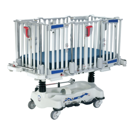
SIDERAIL ACTIVATION HANDLE LITTER LIFT PEDAL OXYGEN BOTTLE RETAINING COLLAR OPTIONAL OPTIONAL GROUND CHAIN IV CADDY ARM OPTIONAL PNEUMATIC HEAD SECTION LOWER PEDAL ACTIVATION LEVER OPTIONAL Figure 1 - Bed illustration Return To Table of Contents www.stryker.com 1900-009-002 REV B 1-11... -
Page 14: Contact Information
Introduction CONTACT INFORMATION Contact Stryker Customer Service or Technical Support at 1-800-327-0770. Stryker Medical 3800 E. Centre Avenue Portage, Michigan 49002 Return To Table of Contents 1-12 1900-009-002 REV B www.stryker.com... -
Page 15: Summary Of Safety Precautions
• Do not use the stretcher if any components are missing or broken. Contact your dealer or Stryker for replacement parts. Use only replacement parts provided by Stryker. - Page 16 • Over-tightening the P.C. valve may cause damage to the valve itself, the O-ring seal, or the jack base. Note • Throughout the manual, the words “right” and “left” refer to the right and left sides of a patient lying face up on the stretcher. Return To Table of Contents 1-14 1900-009-002 REV B www.stryker.com...
-
Page 17: Static Discharge Precautions
2 and 3 of the following procedure. Do not place unprotected circuit boards on the floor. All circuit boards to be returned to Stryker Medical should be shipped in the static shielding bags the new boards were shipped in. Static Protection Procedure Unplug the power cord from the wall receptacle. -
Page 18: Setup
Both release knob open/close indicators show green when the door is closed and locked, and yellow when the door is open. Verify that the access doors are properly closed and locked when both open/close indicators show green. Return To Table of Contents 1-16 1900-009-002 REV B www.stryker.com... -
Page 19: Scale System Calibration
Press the Weigh / On button. 10. “R-r” will now show in the display. Place the weight(s) on the foot right corner of the litter and wait five seconds. Press the Weigh / On button. Return To Table of Contents www.stryker.com 1900-009-002 REV B 1-17... - Page 20 Ensure the measurements taken are within the ± 0.5 lb. (0.2 kg) at 50 lb. (22 kg) or less or ± 1.0 lb. (0.4 kg) at ≥ 50 lb. (22 kg) tolerance. Return To Table of Contents 1-18 1900-009-002 REV B www.stryker.com...
-
Page 21: Scale System Verification (Optional)
± 0.5 lb. (0.2 kg) at 50 lb. (22 kg) or less and within ± 1.0 lb. (0.4 kg) at ≥ 50 lb. (22 kg) when flat. Return To Table of Contents www.stryker.com 1900-009-002 REV B 1-19... -
Page 22: Cleaning
Quaternary Cleaners: identified by ingredients containing the phrase “…yl ammonium chloride” Quat/Isopropyl Cleaners: identified by a quaternary ingredient above plus isopropyl alcohol Phenolic Cleaners: identified by ingredients containing the suffix “-phenol” Chlorine Bleach: known generically as “Sodium Hypochlorite Return To Table of Contents 1-20 1900-009-002 REV B www.stryker.com... -
Page 23: Special Instructions
Rinse surfaces which have been exposed to the solution with clear water before returning mattress to service. NOTE Failure to follow the above directions when using these types of cleaners may void this product’s warranty. Return To Table of Contents www.stryker.com 1900-009-002 REV B 1-21... -
Page 24: Preventive Maintenance
Optional retracting protective top secure and working properly. ____ Optional I.V. Caddy secure and working properly. ____ Standard or optional premium accessory brackets secure. Stretcher Serial Number: Completed by: _______________________________________ Date: ___________________ Return To Table of Contents 1-22 1900-009-002 REV B www.stryker.com... -
Page 25: Grease Points (Hydraulic Base)
If dry, apply a thin layer of OG2 Grease (p/n M0027) to the Jack Springs. Apply OG2 Grease (p/n M0027) to the Descent Valve Pins. BOTH HEAD AND FOOT END JACK SPRINGS Head End shown BOTH HEAD AND FOOT END DESCENT VALVE PINS Return To Table of Contents www.stryker.com 1900-009-002 REV B 1-23... -
Page 26: Scale System Error Codes
The analog-to-digital converter (ADC) response timed out. This error may occur during the calibration of the ADC. • Restart the calibration process. • Contact Technical Support if the problem persists. Return To Table of Contents 1-24 1900-009-002 REV B www.stryker.com... - Page 27 Location of the cells in relation to the number it is associated with in the cell verification module: Cell 0 - Foot Right Cell 1 - Head Right Cell 2 - Head Left Cell 3 - Foot Left Return To Table of Contents www.stryker.com 1900-009-002 REV B 1-25...
-
Page 28: Quick Reference Replacement Parts
The parts and accessories listed on this page are all currently available for purchase. Some of the parts identified on the assembly drawing parts in this manual may not be individually available for purchase. Please call Stryker Customer Service USA: 1-800-327-0770 for availability and pricing. -
Page 29: Service
Using a floor jack, raise the end of the stretcher near the caster(s) needing repair approximately 9 in. off the floor. Using the Stryker Special key and a 3/4 in. socket, remove the locknut and washer (A) holding the caster (B) to the base. -
Page 30: Caster Replacement (Hydraulic Base)
Remove the defective caster. Reverse the above steps to reinstall the replacement caster. Verify proper operation of the caster before replacing the base hood and returning the stretcher to service. Figure 4 Return To Table of Contents 1-28 1900-009-002 REV B www.stryker.com... -
Page 31: Th Wheel Arm Assembly (Fixed Base)
11. Reverse the above steps install the new wheel arm assembly and reinstall the fifth wheel assembly on to the base frame. 12. Verify proper operation of the fifth wheel when it is engaged before returning the stretcher to service. Figure 5 Return To Table of Contents www.stryker.com 1900-009-002 REV B 1-29... -
Page 32: Th Wheel Arm Assembly (Hydraulic Base)
12. Reverse the above steps install the new wheel arm assembly and reinstall the fifth wheel assembly on to the base frame. 13. Verify proper operation of the fifth wheel and brakes before returning the stretcher to service. Figure 6 Return To Table of Contents 1-30 1900-009-002 REV B www.stryker.com... -
Page 33: Fifth Wheel Caster Replacement
Tighten the fasteners. Verify proper operation of the 5 wheel before replacing the base hood and returning the stretcher to service. Return To Table of Contents www.stryker.com 1900-009-002 REV B 1-31... -
Page 34: Brake / Steer Pedal Replacement
Using a hammer, drive the spring pin in until it is flush to the top of the pedal. Verify proper operation of the Brake / Steer pedal before returning the stretcher to service. Return To Table of Contents 1-32 1900-009-002 REV B www.stryker.com... -
Page 35: Brake Bar Replacement (Hydraulic Base)
• (2) 1/2 in. Combination Wrenches • 9/16 in. Combination Wrench • 5/8 in. Combination Wrench • (2) Bungee Cords (or equivalent) • OG2 Grease (Stryker p/n: M0027) PROCEDURE: Raise the litter and the rails to the highest position. Lift the base hood, separating the Velcro fasteners holding it to the base, and support it using bungee cords. -
Page 36: Brake Adjustment Procedure (Hydraulic Base)
Using a 3/4 in. socket, screw in the locknut (B) and test the brakes. Repeat until a proper brake adjustment is found. Using a 3/4 in. combination wrench and a 3/4 in. socket, tighten the jam nut (A). Remove the bungee cords and replace the base hood. Figure 10 Return To Table of Contents 1-34 1900-009-002 REV B www.stryker.com... -
Page 37: Hydraulic Jack Replacement (Hydraulic Base)
• 3/8 in. Drive Ratchet • 1/2 in. Combination Wrench • 9/16 in. Combination Wrench • Spring Compression Tool (Stryker p/n: 1210-001-003) • OG2 Grease (Stryker p/n: M0027) PROCEDURE: Remove the litter (see “Litter Removal - Hydraulic Base Stretcher” procedure, page 1-51). -
Page 38: Hydraulic Fluid Level Check (Hydraulic Base)
• (2) Bungee Cords (or equivalent) • 3/4 in. Socket • 3/8 in. Drive Ratchet • Mobil Aero HFA Hydraulic Fluid (Stryker p/n: 2020-070-475) PROCEDURE: Raise the rails to the highest position and lower the litter to the lowest height. Apply the brakes. -
Page 39: Constant Flow Jack Descent Rate Adjustment (Hydraulic Base)
Raise the litter to the highest position, and continue to actuate the system several times. This will force the air through the system and allow the jack to function properly. Return To Table of Contents www.stryker.com 1900-009-002 REV B 1-37... -
Page 40: Poppet Valve Replacement (Hydraulic Base)
Pump the jack to the highest height. Apply weight to the stretcher and ensure the jack holds. Verify there are no hydraulic leaks. 10. Remove the bungee cords and replace the base hood. Return To Table of Contents 1-38 1900-009-002 REV B www.stryker.com... -
Page 41: Check Valve Replacement (Hydraulic Base)
11. Pump the jack to the maximum height. Apply weight to the stretcher and ensure the jack holds. Verify there are no hydraulic leaks. 12. Remove the bungee cords and replace the base hood. Return To Table of Contents www.stryker.com 1900-009-002 REV B 1-39... -
Page 42: Adjustable Pressure Compensated (P.c.) Valve Replacement (Hydraulic Base)
Pump the jack to the highest position. Apply weight to the stretcher and ensure the jack holds. Verify there are no hydraulic leaks. Remove the bungee cords and replace the base hood. Return To Table of Contents 1-40 1900-009-002 REV B www.stryker.com... -
Page 43: Pump Pedal Replacement (Hydraulic Base)
Align the holes on the new pump pedal and the pedal rod and fit the pump pedal on the pedal rod. Using a pop rivet tool, install the new uni-lower pedal. Verify proper operation of the uni-lower pedal before returning the bed to service. Return To Table of Contents www.stryker.com 1900-009-002 REV B 1-41... -
Page 44: Scale Membrane Replacement
10. Reverse the above steps to install the new accessory bracket cover. Note The new accessory bracket cover includes the membrane and all applicable labels. 11. Verify proper operation of the scale controls before returning the stretcher to service. Return To Table of Contents 1-42 1900-009-002 REV B www.stryker.com... -
Page 45: Scale Control Board Replacement
1-45, for the load cell cable connections to the control board. 14. Calibrate the scale system (see “Scale Calibration”, page 1-17). 15. Verify proper operation of the scale controls before returning the stretcher to service. Return To Table of Contents www.stryker.com 1900-009-002 REV B 1-43... -
Page 46: Load Cell Replacement
When installing new cable ties on the load cell cable, ensure the load cell has a 1 in. radius curve at the first point it is secured. Leave a small amount of slack in the cable as the remainder of the cable ties are installed. This will allows for the movement of the stretcher. Return To Table of Contents 1-44 1900-009-002 REV B www.stryker.com... - Page 47 13. Calibrate the scale system (see “Scale System Calibration”, page 1-17). 14. Verify proper operation of all scale functions before returning the stretcher to service. POSITION #1 Figure 15 Figure 16 Return To Table of Contents www.stryker.com 1900-009-002 REV B 1-45...
-
Page 48: Angle Sensor Replacement (Scale Option)
Use only 1.5 VDC batteries. Use of other voltage and/or types may damage the scale system. Remove the batteries if the scale system or stretcher will not be used for long periods of time. Return To Table of Contents 1-46 1900-009-002 REV B www.stryker.com... -
Page 49: Head Section Replacement
(B) holding the head section to the two coupling bars. Remove the head section. Reverse the above steps to install the new head section. Verify proper operation of the head section before returning the stretcher to service. Return To Table of Contents www.stryker.com 1900-009-002 REV B 1-47... -
Page 50: Head Section Pneumatic Cylinder Replacement
Verify proper operation of the head section before reinstalling the protective plate and returning the stretcher to service. Return To Table of Contents 1-48 1900-009-002 REV B www.stryker.com... -
Page 51: Head Section Support Arm Replacement
In order for the head section to function properly, the cable end nuts must be adjusted. Ensure there is no play in the activation lever. Verify proper operation of the head section before returning the stretcher to service. Return To Table of Contents www.stryker.com 1900-009-002 REV B 1-49... -
Page 52: Litter Removal - Fixed Base Stretcher
Reverse the above steps to reinstall the litter frame. Verify proper operation of the stretcher before returning it to service. Figure 22 Figure 21 Return To Table of Contents 1-50 1900-009-002 REV B www.stryker.com... -
Page 53: Litter Removal - Hydraulic Base Stretcher
The two bolts must be replaced. The Scotch-Grip coating is less effective once the screw have been tightened and removed thereafter. Reverse the above steps to reinstall the litter frame. Verify proper operation of the stretcher before returning it to service. Return To Table of Contents www.stryker.com 1900-009-002 REV B 1-51... -
Page 54: Siderail / Endrail Handle Assembly Replacement
ENDRAIL CENTRAL COLUMN ASSEMBLY REPLACEMENT WARNING Only service technicians from Stryker or service personnel trained by Stryker should perform this procedure. Failure to comply can result in serious damage to the bed and/or severe injury to users or patients. TOOLS REQUIRED: • #1 Phillips Screwdriver... - Page 55 (V) using a 3/32 in. Allen wrench until the proper alignment is achieved. 21. Verify the handle and four rail positions (lower, 9 in., 14 in., upper) for proper operation before reinstalling the brake shoe cover and returning the stretcher to service. Return To Table of Contents www.stryker.com 1900-009-002 REV B 1-53...
-
Page 56: Endrail Central Column Spring Replacement
ENDRAIL CENTRAL COLUMN SPRING REPLACEMENT WARNING Only service technicians from Stryker or service personnel trained by Stryker should perform this procedure. Failure to comply can result in serious damage to the bed and/or severe injury to users or patients. TOOLS REQUIRED: • #1 Phillips Screwdriver... - Page 57 (V) using a 3/32 in. Allen wrench until the proper alignment is achieved. 23. Verify the handle and four rail positions (lower, 9 in., 14 in., upper) for proper operation before reinstalling the brake shoe cover and returning the stretcher to service. Return To Table of Contents www.stryker.com 1900-009-002 REV B 1-55...
-
Page 58: Siderail Central Column Assembly Replacement (Rails With Moving Access Doors)
SIDERAIL CENTRAL COLUMN ASSEMBLY REPLACEMENT (RAILS WITH MOVING ACCESS DOORS) WARNING Only service technicians from Stryker or service personnel trained by Stryker should perform this procedure. Failure to comply can result in serious damage to the bed and/or severe injury to users or patients. - Page 59 (V) using a 3/32 in. Allen wrench until the proper alignment is achieved. 22. Verify the handle and four rail positions (lower, 9 in., 14 in., upper) for proper operation before reinstalling the brake shoe cover and returning the stretcher to service. Return To Table of Contents www.stryker.com 1900-009-002 REV B 1-57...
-
Page 60: Siderail Central Column Spring Replacement (Rails With Moving Access Doors)
SIDERAIL CENTRAL COLUMN SPRING REPLACEMENT (RAILS WITH MOVING ACCESS DOORS) WARNING Only service technicians from Stryker or service personnel trained by Stryker should perform this procedure. Failure to comply can result in serious damage to the bed and/or severe injury to users or patients. - Page 61 (V) using a 3/32 in. Allen wrench until the proper alignment is achieved. 24. Verify the handle and four rail positions (lower, 9 in., 14 in., upper) for proper operation before reinstalling the brake shoe cover and returning the stretcher to service. Return To Table of Contents www.stryker.com 1900-009-002 REV B 1-59...
-
Page 62: Siderail Central Column Assembly Replacement (Rails With Fixed Access Doors)
13. Lift the defective central column to remove it. Use caution to avoid damaging the seal. Set the defective coulmn aside. Note The seal must be replaced if it is damaged during the procedure. Do not install a damaged seal. Return To Table of Contents 1-60 1900-009-002 REV B www.stryker.com... - Page 63 (V) using a 3/32 in. Allen wrench until the proper alignment is achieved. 23. Verify the handle and four rail positions (lower, 9 in., 14 in., upper) for proper operation before reinstalling the brake shoe cover and returning the stretcher to service. Return To Table of Contents www.stryker.com 1900-009-002 REV B 1-61...
-
Page 64: Upper Plastic Cover Replacement
Remove the two access doors by moving the lower end of the door to the left or right and disengaging it from the upper hinge (H) (see Figure 28, page 1-66). Keep the spacers and the hinges. Return To Table of Contents 1-62 1900-009-002 REV B www.stryker.com... -
Page 65: Lower Plastic Cover Replacement
Remove the defective lower cover. Reverse the above steps to install the new lower cover. Verify proper operation of the rails before returning the stretcher to service. Return To Table of Contents www.stryker.com 1900-009-002 REV B 1-63... -
Page 66: Rail Support Rolling Bearing Replacement
Ensure the spring pin is centered so the rolling bearing assembly will properly fit into the rail support. Reinstall the rolling bearing support and cover. Verify proper operation of the rail before returning the stretcher to service. Return To Table of Contents 1-64 1900-009-002 REV B www.stryker.com... -
Page 67: Rail Assist Cable Replacement
Service RAIL ASSIST CABLE REPLACEMENT WARNING Use only Stryker p/n: 19-0381 to replace the rail assist cable. Using a different cable may cause severe injury to the patient or user and damage to the stretcher. TOOLS REQUIRED: • #1 Phillips Screwdriver • #2 Phillips Screwdriver... -
Page 68: Access Door Replacement
Remove the access door by moving the lower end of the door to the left or right and disengaging it from the upper hinge. Reverse the above steps to install the new access door. Verify proper operation of the access door before returning the stretcher to service. Return To Table of Contents 1-66 1900-009-002 REV B www.stryker.com... -
Page 69: Access Door Upper Cover Replacement
(Z). Remove the defective lower cover. Reverse the above steps to install the access door lower cover and reinstall the access door. Verify proper operation of the access door before returning the stretcher to service. Return To Table of Contents www.stryker.com 1900-009-002 REV B 1-67... -
Page 70: Access Door Hinge Replacement
12. Reverse the above steps to install the new upper and lower hinges and reinstall the access door. 13. Verify proper operation of the access door before returning the stretcher to service. Return To Table of Contents 1-68 1900-009-002 REV B www.stryker.com... -
Page 71: Access Door Release Knob Replacement
Reverse the above steps to install the new locking bars and compression spring. Note Apply OG2 grease to the new compression spring before installing it. 10. Verify proper operation of the rail before returning the stretcher to service. Return To Table of Contents www.stryker.com 1900-009-002 REV B 1-69... -
Page 72: Fixed Height Base
Fixed Height Base OL190247W Rev 00 (Reference only) Return To Table of Contents 1-70 1900-009-002 REV B www.stryker.com... - Page 73 Nylon Hex Locknut VB15A1O44FT Hex Bolt VE30A1O Nylon Hex Locknut 19-0634 Hood Velcro Fastener 19-0658W Fixed Base VV81A9E16 Flat Head Tapping Screw 19-0527 Ground Chain VB15A1O24-S Hex Bolt QDF5053 Black Bellow Return To Table of Contents www.stryker.com 1900-009-002 REV B 1-71...
-
Page 74: Fixed Height Base With Scale Option
Fixed Height Base with Scale Option OL190246W Rev 00 (Reference only) Return To Table of Contents 1-72 1900-009-002 REV B www.stryker.com... - Page 75 Nylon Hex Locknut VB15A1O44FT Hex Bolt VE30A1O Nylon Hex Locknut 19-0634 Hood Velcro Fastener 19-0956W Reinforced Fixed Base VV81A9E16 Flat Head Tapping Screw 19-0527 Ground Chain VB15A1O24-S Hex Bolt QDF5053 Black Bellow Return To Table of Contents www.stryker.com 1900-009-002 REV B 1-73...
-
Page 76: Optional 5 Th Wheel Assembly, Fixed Base
VE10A1O Hex Nut VB15A1O50 Hex Bolt QREB-690 Spring 19-0272W Wheel Shaft VD60A1N2410 Shoulder Bolt 19-0624Z Right Support Plate 19-0811 Neutral Wheel VB15A1O32 Hex Bolt VB15A1O52 Hex Bolt VB15A1O40 Hex Bolt Return To Table of Contents 1-74 1900-009-002 REV B www.stryker.com... -
Page 77: Fixed Base Frame Support Without Scale Option
Fixed Base Frame Support without Scale - OL190149-XXX Rev D (Reference Only) Item Part No. Part Name Qty. 19-0940P Fixed Height Base Frame Support VE30A1O Nylon Hex Locknut VB35A1O24 Carriage Bolt QE71-0516-XXX Manufacturer Label Return To Table of Contents www.stryker.com 1900-009-002 REV B 1-75... -
Page 78: Fixed Based Frame Support With Scale Option
REMOVING THE AXIS TREAD AFTER X.X. X.X. INSTALLATION BOLTS OF FIXATION THE ROCKER. Coil foot end load cell cables and attach as shown. Head Right Head Left Foot Left Foot Right Return To Table of Contents 1-76 1900-009-002 REV B www.stryker.com... - Page 79 QDF17-0138 PC Board Ground Wire QE71-0674-F Load Cell Position Label, Head Right 1 QE71-0673-F Load Cell Position Label, Head Left 1 QE71-0667-T Manufacturer Label QDF9518 Cable Tie 19-0976P Frame Support Return To Table of Contents www.stryker.com 1900-009-002 REV B 1-77...
-
Page 80: Base Hood Without Iv Caddy
Base Hood without IV Caddy OL190235 Rev 00 (Reference only) Item Part No. Part Name Qty. QP19-0359 Base Hood Return To Table of Contents 1-78 1900-009-002 REV B www.stryker.com... -
Page 81: Hydraulic Base Assembly
Hydraulic Base Assembly L19-014 Rev 01 (Reference only) Return To Table of Contents www.stryker.com 1900-009-002 REV B 1-79... - Page 82 Activation Pedal Support VV60A0G08-S Hex Socket Set Screw M0019 Petro Canada OG2 Grease .24 kg VE30A1P Nylon Hex Locknut QDB7812 Grey Anti-slip Tape .167 ft QPNI2402 Nylon Bushing VG40B0316 Cotter Pin Return To Table of Contents 1-80 1900-009-002 REV B www.stryker.com...
-
Page 83: Hydraulic Base Brake Assembly
BEDS WITH OPTION OL190006 NO TIGHTENING TORQUE, BRAKE ADJUSTMENT NUT 36* 2* 21 6 Pedal without 5 Wheel 28,8 28,8 28,8 28,8 28,8 28,8 28,8 28,8 Pedal with 5 Wheel Return To Table of Contents www.stryker.com 1900-009-002 REV B 1-81... - Page 84 Pan Head Machine Screw 19-0810Z Left Support Plate VE30A0G Nylon Hex Locknut QR19-0812 Neutral Guide Plate QDB7812 Grey Anti-slip Tape .083 ft VW20A10 Spring Washer VE10A1O Hex Nut QREB-690 Spring VB15A1O52 Hex Bolt Return To Table of Contents 1-82 1900-009-002 REV B www.stryker.com...
-
Page 85: Constant Descent Jack Assembly - Qdf5060
Parker Packing 0926-020-162 Wear Ring 5050-370-100 Jack Base Assembly 0004-014-000 Socket Head Cap Screw 0045-014-000 O-Ring 0045-110-000 O-Ring 0045-904-000 O-Ring 0045-978-000 O-Ring 0719-070-211 Jack Assembly Label 0921-001-252 Serial Number Label Return To Table of Contents www.stryker.com 1900-009-002 REV B 1-83... -
Page 86: Jack Base Assembly
0926-020-154 Seal 1210-170-013 Base Plug 2025-075-087 Pin Housing 5050-170-050 Adjustable P.C. Valve Cartridge 5050-370-110 Jack Base, Machined 0038-311-000 Compression Spring 0004-006-000 O-Ring 0045-966-000 O-Ring 0045-967-000 O-Ring 0715-001-321 Check Valve Screen Return To Table of Contents 1-84 1900-009-002 REV B www.stryker.com... -
Page 87: Optional 5 Th Wheel Assembly, Hydraulic Base
Flat Head Hex Socket Cap Screw 17-0243 Wheel Bushing 17-0104Z Wheel Support 17-0124W Wheel Spring 17-0061W Clearance Arm 19-0272W Wheel Shaft 28-0150Z Counter Lever QDF17-0020 Shoulder Spacer VB15A1O32 Hex Bolt Return To Table of Contents www.stryker.com 1900-009-002 REV B 1-85... -
Page 88: Hydraulic Base Frame Support Without Scale Option
Molded Frame Bushing VB35A1O24 Carriage Bolt M0019 Petro Canada OG2 Grease .24 kg VB15A1O24 Hex Bolt 19-0156Z Slider Rail 19-0482P Foot Section Glider 19-0938P Frame Support, Foot End QE71-0516-XXX Manufacturer Label Return To Table of Contents 1-86 1900-009-002 REV B www.stryker.com... -
Page 89: Hydraulic Base Frame Support With Scale Option
Head Right Head Left Foot Left Foot Right T130 T450 T450 T450 POSITION #1 T450 T450 T130 17 T75 2 T130 T15 29 CONNECT TO THE PC BOARD FOOT Return To Table of Contents www.stryker.com 1900-009-002 REV B 1-87... - Page 90 Angle Sensor Wire QDF75-0470 Angle Sensor Card 19-0943 Angle Sensor Support VE30A0G Nylon Hex Locknut VV33A0G24 Pan Head Machine Screw M0005 Glue .1 kg QE71-0667-T Manufacturer Label QDF9518 Black Cable Tie Return To Table of Contents 1-88 1900-009-002 REV B www.stryker.com...
-
Page 91: Hydraulic Base Labels
Hydraulic Base Labels OL190078-XXX Rev 02 (Reference only) Item Part No. Part Name Qty. QE71-0447-XXX Hydraulic Base Label, Left QE71-0511 Brake Label QE71-0459-XXX Hydraulic Base Label, Right Return To Table of Contents www.stryker.com 1900-009-002 REV B 1-89... -
Page 92: Th Wheel Option Labels
Wheel Option Labels OL190081-XXX Rev 02 (Reference only) Item Part No. Part Name Qty. QE71-0497-XXX Wheel Left Label QE71-0496 Wheel Green Label QE71-0512-XXX Wheel Right Label Return To Table of Contents 1-90 1900-009-002 REV B www.stryker.com... -
Page 93: Litter Frame
Pan Head Machine Screw QPCD0903 Rubber Bumper VE30A1E Nylon Hex Locknut VR11H64 Pop Rivet 19-0715Z Spring Hitch Plate 19-0578P Lower Cover Plate, Foot End 19-0579P Lower Cover Plate, Head End Return To Table of Contents www.stryker.com 1900-009-002 REV B 1-91... -
Page 94: Siderail Assist System
Shoulder Screw VW10A10 Washer VE40A1O Cap Nut VB35A1O24-S Hex Bolt 19-0452W Brake Shoe Support 19-0364Z Brake Shoe QP19-0411-10 Brake Shoe Cover QDF19-0374ZN Right Stop Catch VV60B0G12 Set Screw VE80A0G “K-lok” Locknut Return To Table of Contents 1-92 1900-009-002 REV B www.stryker.com... -
Page 95: Endrail Assist System
Brake Shoe Cover QDF19-0374ZN Right Stop Catch VD60B1N36 Shoulder Screw 19-0364Z Brake Shoe 19-0997 Assist System Cable VB35A1O24-S Hex Bolt QDB7812 Grey Anti-slip Tape .1667 ft VV60B0G12 Set Screw VE80A0G “K-lok’ Locknut Return To Table of Contents www.stryker.com 1900-009-002 REV B 1-93... -
Page 96: Head End Standard Accessory Brackets
VE30A1N Nylon Hex Locknut VW10A08 Washer 19-0833W Standard Support, Left 19-0973C Fixed Socket for Std. Accessory Brkt. 2 VW11A12 Washer VW20A12 Lock Washer VB15A1P24 Hex Bolt VE30A1P Nylon Hex Locknut Return To Table of Contents 1-94 1900-009-002 REV B www.stryker.com... -
Page 97: Footend Standard Accessory Brackets
Nylon Locknut VE30A1N Nylon Locknut VW10A08 Washer 19-0833W Standard Support, Left 19-0973C Fixed Socket for Std. Accessory Brkt. 2 VW11A12 Washer VW20A12 Lock Washer VB15A1P24 Hex Bolt VE30A1P Nylon Hex Locknut Return To Table of Contents www.stryker.com 1900-009-002 REV B 1-95... -
Page 98: Standard Accessory Brackets With Scale Option
Nylon Hex Locknut QE71-0654-F Electronic Component Label 1 QP19-0868 Bracket Cover w/ Scale QE18545 ‘Refer to Manual’ Label 19-0777C Fixed Socket QDF19-0867 Scale Membrane QE71-0680-F ‘Weighing Zone’ Label QDF19-0888 Scale PC Board Return To Table of Contents 1-96 1900-009-002 REV B www.stryker.com... -
Page 99: Premium Accessory Brackets With Scale Option
Part Name Qty. Item Part No. Part Name Qty. QP19-0357 Bracket Cover, Left VW10A10 Washer QE71-0346 ‘Stryker’ Label VE30A1O Nylon Hex Locknut QE71-0655-F I.V. Pole Label QE71-0654-F ‘Electronic Component’ Label 1 QE71-0534-BIL Oxygen Bottle and I.V. Pole QP19-0868 Bracket Cover with Scale... -
Page 100: Head Section With Support Arm
VR11H64 Pop Rivet 19-0652P Head Section Stop Notch, Right QE71-0538-F Inspection Label QE71-0451 Foot Section Elevation Label, Left 19-0749P Foot Section Support with Caps QE71-0452 Foot Section Elevation Label, Right Return To Table of Contents 1-98 1900-009-002 REV B www.stryker.com... -
Page 101: Head Section With Lift Assist
Head Section with Lift Assist OL190024 Rev K (Reference only) Return To Table of Contents www.stryker.com 1900-009-002 REV B 1-99... - Page 102 QDF19-0815 Head Section Cable, Short QE71-0538-F Inspection Label QE71-0451 Foot Section Elevation Label, Left QPNI2404 Nylon Shoulder Bushing 19-0749P Foot Section Support with Caps QE71-0452 Foot Section Elevation Label, Right Return To Table of Contents 1-100 1900-009-002 REV B www.stryker.com...
-
Page 103: Fixed Endrails
Fixed Endrails 19-0799L Rev - (Reference only) Fixed Endrails - OL190027W Rev - - (Reference only) Item Part No. Part Name Qty. OL190015W Fixed Endrail Return To Table of Contents www.stryker.com 1900-009-002 REV B 1-101... -
Page 104: Fixed Footrail, Adjustable Headrail Without 9 In Double Safety Lock
Fixed Footrail, Adjustable Headrail, without Double Safety Lock - OL190142-XXX Rev 11 - (Reference only) Item Part No. Part Name Qty. OL190141-XXX Central Locking Column w/o 9 in Double Safety Lock OL190010 Adjustable Endrail OL190020 Endrail Assist System OL190015 Fixed Endrail Return To Table of Contents 1-102 1900-009-002 REV B www.stryker.com... -
Page 105: Fixed Footrail, Adjustable Headrail With 9 In Double Safety Lock
Fixed Footrail, Adjustable Headrail with Double Safety Lock - OL190013W Rev 01 - (Reference only) Item Part No. Part Name Qty. OL190026W Central Locking Column with 9 in Double Safety Lock OL190010W Adjustable Endrail OL190020W Endrail Assist System OL190015W Fixed Endrail Return To Table of Contents www.stryker.com 1900-009-002 REV B 1-103... -
Page 106: Adjustable Endrails Without 9 In Double Safety Lock
Adjustable Endrails without Double Safety Lock - OL190138-XXX Rev 02 - (Reference only) Item Part No. Part Name Qty. OL190141-XXX Central Locking Column, without 9 in Double Safety Lock OL190010 Adjustable Endrail OL190020 Endrail Assist System Return To Table of Contents 1-104 1900-009-002 REV B www.stryker.com... -
Page 107: Adjustable Endrails With 9 In Double Safety Lock
Adjustable Endrails with Double Safety Lock - OL190021W Rev - - (Reference only) Item Part No. Part Name Qty. OL190026W Central Locking Column with 9 in Double Safety Lock OL190010W Adjustable Endrail OL190020W Endrail Assist System Return To Table of Contents www.stryker.com 1900-009-002 REV B 1-105... -
Page 108: Fixed Endrail Assembly
Nylon Hex Locknut VE20A1O Hex Jam Nut VV83A9A20HL Pan Head Tapping Screw 19-0869Z Floating Nut 19-0649 Perforated Siderail Cover 19-0861W Adjustment Support VB18A1O36 Hex Bolt VVZ7A1E32 Pan Head Tapping Screw Return To Table of Contents 1-106 1900-009-002 REV B www.stryker.com... -
Page 109: Adjustable Endrail Assembly
VE30A1O Nylon Hex Locknut 19-0305 Rolling Bearing Support VB35A1O24 Carriage Bolt 19-0859Z Moving Siderail Support QP19-0256-10 Barrel Cover 19-0263P Inner Oval Post 19-0513C Sliding Guide Post 19-0264P End Oval Post Return To Table of Contents www.stryker.com 1900-009-002 REV B 1-107... -
Page 110: Siderails Without Access Doors And 9 In Double Safety Lock
Part Name Qty. OL190022 Fixed Access Door, Left OL190141-XXX Central Locking Column w/o 9 in Double Safety Lock OL190014 Siderail Common Components OL190018 Fixed Access Door, Right OL190019 Siderail Assist System Return To Table of Contents 1-108 1900-009-002 REV B www.stryker.com... -
Page 111: Siderails With Access Doors, Without 9 In Double Safety Lock
Part No. Part Name Qty. OL190016 Access Door, Left OL190141-XXX Central Locking Column w/o 9 in Double Safety Lock OL190014 Siderail Common Components OL190017 Access Door, Right OL190019 Siderail Assist System Return To Table of Contents www.stryker.com 1900-009-002 REV B 1-109... -
Page 112: Siderails Without Access Doors, With 9 In Double Safety Lock
Part Name Qty. OL190018W Fixed Access Door, Right OL190026W Central Locking Column with 9 in Double Safety Lock OL190014W Siderail Common Components OL190022W Fixed Access Door, Left OL190019W Siderail Assist System Return To Table of Contents 1-110 1900-009-002 REV B www.stryker.com... -
Page 113: Siderails With Access Doors And 9 In Double Safety Lock
Part No. Part Name Qty. OL190016W Access Door, Left OL190026W Central Locking Column with 9 in Double Safety Lock OL190014W Siderail Common Components OL190017W Access Door, Right OL190019W Siderail Assist System Return To Table of Contents www.stryker.com 1900-009-002 REV B 1-111... -
Page 114: Siderail Common Components
VE20A1O Hex Jam Nut QP19-0468 Siderail Cover 19-0869Z Floating Nut VB18A1O36 Hex Bolt 19-0861P Adjustment Support VVZ7A1E32 Pan Head Tapping Screw VW10A10 Washer 19-0509Z Siderail Structural Member QP19-0469 Siderail Cover Return To Table of Contents 1-112 1900-009-002 REV B www.stryker.com... -
Page 115: Fixed Access Door, Right
Access Door Perforated Cover VV83A9A24HL Truss Head Tapping Screw VVZ7A1E32 Pan Head Tapping Screw 19-0487Z Access Door Spacer QP19-0554-10 Access Door Cover 19-0653 Access Door Perforated Cover 19-0283P Access Door Post Return To Table of Contents www.stryker.com 1900-009-002 REV B 1-113... -
Page 116: Fixed Access Door, Left
VV10A1G24-S Hex Socket Head Cap Screw 19-0622 Hinge Sleeve 19-0791Z Access Door Hinge 19-0487Z Access Door Spacer QP19-0638-10 Access Door Cover 19-0655 Access Door Perforated Cover 19-0283P Access Door Post Return To Table of Contents 1-114 1900-009-002 REV B www.stryker.com... -
Page 117: Access Door, Left
Inner Hinge QP19-0553-10 Access Door Cover 19-0288Z Access Door Structural Member 19-0654 Access Door Perforated Cover VV83A9A24HL Truss Head Tapping Screw QP19-0638-10 Access Door Cover 19-0655 Access Door Perforated Cover Return To Table of Contents www.stryker.com 1900-009-002 REV B 1-115... -
Page 118: Access Door, Right
Release Knob Label, Orange 19-0283W Access Door Post 19-0335Z Locking Mechanism Bar QRC19-0336 Compression Spring 19-0282W Locking Mechanism Post QP19-0546 Release Knob, Inner QP19-0545 Release Knob, Outer QE71-0456 Latch Release Knob Label, Green Return To Table of Contents 1-116 1900-009-002 REV B www.stryker.com... -
Page 119: Central Column Without 9 In Double Safety Lock
Washer QPN-13-0159 Nylon Bushing QE71-0624-XXX Without 9 in Double Safety 19-0515P Central Locking Column Lock’ Label VVZ7A1E32 Pan Head Tapping Screw 19-0807Z Handle Cam VV31K0G20 Machine Screw 19-0491Z Push Bar Return To Table of Contents www.stryker.com 1900-009-002 REV B 1-117... -
Page 120: Central Column With 9 In Double Safety Lock
Siderail 26 in Position Label 2 VV23A9A16 Pan Head Tapping Screw VW10A05 Washer QPN-13-0159 Nylon Bushing 19-0515W Central Locking Column VVZ7A1E32 Pan Head Tapping Screw 19-0807Z Handle Cam VV31K0G20 Machine Screw 19-0491Z Push Bar Return To Table of Contents 1-118 1900-009-002 REV B www.stryker.com... -
Page 121: Access Door Label Color Options
QE71-0501-5 Right Label, Green OL190033 (Ref.) QE71-0500-5 Left Label, Green QE71-0501-6 Right Label, Burgundy OL190034 (Ref.) QE71-0500-6 Left Label, Burgundy QE71-0501-2 Right Label, Grey OL190035 (Ref.) QE71-0500-2 Left Label, Grey Return To Table of Contents www.stryker.com 1900-009-002 REV B 1-119... -
Page 122: Stretcher Labeling
Qty. QE71-0449 Head End Label QE71-0446-XXX Warning Message Label QE71-0450 Foot End Label QE71-0462 Product Name Label QE71-0521-XXX Warnings Label QE71-0346 Stryker Label QE71-0480 Serial Number Plate VR11H43 Pop Rivet Return To Table of Contents 1-120 1900-009-002 REV B www.stryker.com... -
Page 123: Oxygen Bottle Retaining Collar - Ol190045
Oxygen Bottle Retaining Collar - OL190045 Rev - Item Part No. Part Name Qty. VE30A0G Nylon Hex Locknut VW10A06 Washer QP19-0797-05 Retaining Collar VV33A0G24 Pan Head Machine Screw Return To Table of Contents www.stryker.com 1900-009-002 REV B 1-121... -
Page 124: In Chart Holder - Ol190098 (Right) / Ol190099 (Left)
2 in Chart Holder - OL190098 (Right) / OL190099 (Left) Rev C / Rev C T4.5 Item Part No. Part Name Qty. VE9C Plastic Expansive Nut 19-0648P 2 in Chart Holder VV83A9G24 Pan Head Tapping Screw Return To Table of Contents 1-122 1900-009-002 REV B www.stryker.com... -
Page 125: Iv Caddy, Fixed Height Base - Ol190047-Xxx
VG10B0640 Spring Pin QDF5082 Threaded Rod QDF5084 Storage Clip QDF5083 Storage Clip Support VV10A0G16 Hex Socket Head Cap Screw QE71-0504-XXX I.V. Caddy Label 19-0641 Connecting Arm Assembly VB15A1O40 Hex Bolt Return To Table of Contents www.stryker.com 1900-009-002 REV B 1-123... -
Page 126: Iv Caddy, Hydraulic Base - Ol190046-Xxx
Spring Pin QDF5082 Threaded Rod QDF5084 Storage Clip QDF5083 Storage Clip Support VV10A0G16 Hex Socket Head Cap Screw QE71-0504-XXX I.V. Caddy Label 19-0641 Connecting Arm Assembly VB15A1O40 Hex Bolt VW10A10 Washer Return To Table of Contents 1-124 1900-009-002 REV B www.stryker.com... -
Page 127: Accessories
1-129 X-Ray Cassette Holder, 3/4 in FA64069 page 1-131 X-Ray Cassette Holder, 1-1/4 in FA64076 page 1-131 Removable IV Pole, 1/2 in, Stryker FA64135 page 1-132 Removable IV Pole, 1/2 in FDTSH page 1-133 Two Stage Fixed IV Pole... -
Page 128: Retracting Protective Top - Fa64074-Xxx
QRC19-0839 Protective Top Spring VV33A1N24 Pan Head Machine Screw 19-0680P Upper Hinge Arm VE30A1N Nylon Hex Locknut VW30A0816 Spring Washer QE71-0560-XXX Warning Label 19-0724 Inner Support 19-0679P Lower Hinge Arm Return To Table of Contents 1-126 1900-009-002 REV B www.stryker.com... -
Page 129: Protective Top With Support - Fa64183-Xxx
Locking Bushing 90-1494P Lower Hinge Arm QE71-0780-XXX Move CUB Label QP19-0986-05 Mounting Structure VV83A9G16 Pan Head Tapping Screw QDF5092 Snap Button 90-1480P Support Reinforcement Rail 2 19-0684P Protective Top Post, Left Return To Table of Contents www.stryker.com 1900-009-002 REV B 1-127... -
Page 130: Siderail Pad - Full Perimeter - Dm64085
Siderail Pad - Full Perimeter - DM64085 Return To Table of Contents 1-128 1900-009-002 REV B www.stryker.com... -
Page 131: Upright Oxygen Bottle Holder - Fa64086
Upright Oxygen Bottle Holder - FA64086 L64-0051 Rev 03 (Reference only) Item Part No. Part Name Qty. QDF64-1007 Oxygen Bottle Support 64-0647 Security Chain QE14399-T Manufacturer Label QE71-0601 Maximum Load Label VR11H42 Pop Rivet Return To Table of Contents www.stryker.com 1900-009-002 REV B 1-129... -
Page 132: Defibrillator Tray - Fa64102
Defibrillator Tray - FA64102 L64-0056 (Reference only) Item Part No. Part Name Qty. QDF5091 Defibrillator Tray QE14399-T Label, Manufacturing Return To Table of Contents 1-130 1900-009-002 REV B www.stryker.com... -
Page 133: X-Ray Cassette Holders - 3/4 In - Fa64069 / 1-1/4 In - Fa64076
L64-0045 3/4 in holder L64-0046 1-1/4 in holder Item Part No. Part Name Qty. 64-0537 3/4 in X-ray Cassette Holder 64-0544 1 1/4 in X-ray Cassette Holder QE-14399-T Manufacturer Label Return To Table of Contents www.stryker.com 1900-009-002 REV B 1-131... -
Page 134: Removable Iv Pole, 1/2 In, Stryker - Fa64135
Removable IV Pole, 1/2 in, Stryker - FA64135 L64-059 (Reference only) Item Part No. Part Name Qty. QDF9165 Stryker 1/2 in Removable IV Pole Return To Table of Contents 1-132 1900-009-002 REV B www.stryker.com... -
Page 135: Removable Iv Pole, 1/2 In - Fdtsh
LC-7300 Rev E (Reference only) Item Part No. Part Name Qty. L-2113 Hook 2111A Tightening Sleeve 2109 Compression Socket 2107A Top Tube 2105A Bottom Tube QE14399-T Manufacturer’s Label QPCE1206 Rubber Cap QE71-0246-T Warning Label Return To Table of Contents www.stryker.com 1900-009-002 REV B 1-133... -
Page 136: Two Stage Fixed Iv Pole - Fa64083
QDB19-0741 I.V. Pole Guard Support QDF64-0613 Two Stage I.V. Pole 19-0211C Adaptor VE42A9036 Barrel Nut VV33A1N10-S Pan Head Phillips Machine Head Screw VW20A08 Washer VB15A1N24 Hex Bolt QE71-1306-XXX Warning Label Return To Table of Contents 1-134 1900-009-002 REV B www.stryker.com... -
Page 137: Three Stage Fixed Iv Pole - Fa64084
QDB19-0741 I.V. Pole Guard Support QDF64-0614 Three Stage I.V. Pole 19-0211C Adaptor VE42A9036 Barrel Nut VV33A1N10-S Pan Head Phillips Machine Head Screw VW20A08 Washer VB15A1N24 Hex Bolt QE71-1306-XXX Warning Label Return To Table of Contents www.stryker.com 1900-009-002 REV B 1-135... -
Page 138: Premium Accessory Brackets - Head And Foot Ends - Fa64107
Foot End Only - FA64106 (OL190085) FOOT Premium Accessory Brackets - OL190084-XXX (Head) Rev 02 / OL190085 (Foot) Rev 02 - (Reference only) Item Part No. Part Name Qty. OL190040-XXX Premium Accessory Brackets Return To Table of Contents 1-136 1900-009-002 REV B www.stryker.com... -
Page 139: Premium Accessory Brackets
Accessory Support Socket VE30A1N Nylon Hex Locknut QP19-0358 Accessory Bracket Cover, Rt 1 VW10A08 Washer VB15A1P50 Hex Bolt QE71-0346 Stryker Label VB15A1N24 Hex Bolt QE71-0534-XXX Oxygen Bottle and I.V. Pole QDFP1514 Label 19-0392P Accessory Bracket, Left 19-0777C Fixed Socket QDF5072... -
Page 140: Recycling Passport
Recycling Passport Assembly Part Number: OL190186W (Reference Only) Item Recycling/Material Code Important Information (QDF19-0888) Circuit Board (QDF7909) C Battery Return To Table of Contents 1-138 1900-009-002 REV B www.stryker.com... -
Page 141: Warranty
Stryker’s obligation under this warranty is expressly limited to supplying replacement parts and labor for, or replacing, at its option, any product which is, in the sole discretion of Stryker, found to be defective. If requested by Stryker, products or parts for which a warranty claim is made shall be returned prepaid to the factory. Any improper use or any alteration or repair by others in such manner as in Stryker’s judgment affects the product materially and... - Page 142 Civière pédiatrique ® FL19F/H (190) Guide d’entretien 2014/10 B.0 1900-009-002 REV B www.stryker.com...
- Page 144 Symboles Avertissement/Mise en garde, consulter la documentation d’accompagnement Charge maximale admissible Appareil du type BF Appareil à source électrique interne alimenté par batteries IPX4 Protection contre les projections de liquides Courant direct Conformément à la directive européenne 2002/96/EC sur les rebuts d’équipements électriques et électroniques, ce symbole indique que le produit ne doit pas être disposé...
- Page 146 Remplacement d’un clapet de non-retour (base hydraulique)........2-39 Remplacement d’une soupape compensée par pression réglable (base hydraulique) ....2-40 www.stryker.com 1900-009-002 REV B...
- Page 147 Assemblage de la base du cylindre............2-84 1900-009-002 REV B www.stryker.com...
- Page 148 Support à cassette rayon - 3/4 in FA64069 / 1 1/4 in FA64076........2-131 www.stryker.com 1900-009-002 REV B...
- Page 149 Tige à soluté amovible de Stryker - FA64135........
-
Page 150: Définition De " Avertissement ", " Mise En Garde " Et " Remarque
à prendre afin d’assurer l’utilisation sécuritaire et efficace de l’équipement et d’éviter les dommages qui pourraient découler de son usage ou de son mésusage. Remarque Il s’agit de renseignements spécifiques destinées à faciliter l’entretien ou à clarifier des instructions importantes. Retour à la table des matières www.stryker.com 1900-009-002 REV B... -
Page 151: Introduction
POPULATION DE PATIENTS PRÉVUE: La charge maximale admissible fait référence au poids total du patient, du matelas et des accessoires. La charge maximale admissible pour le lit pédiatrique Stryker Cub est de 45 kg. Ce lit n’est pas conçu pour une utilisation avec un patient dont la taille est supérieure à 89 cm. -
Page 152: Renseignements Techniques
Caractéristiques 6 Vdc, 0,15 A électriques Stryker porte un soin particulier à l’amélioration de ses produits et se réserve le droit d’en changer les spécifications sans préavis. Conforme aux normes suivantes : CSA C22.2, No. 60601.1; UL2601-1; IEC/EN 60601-1. Remarque: La Cub ® est approuvé CE seulement sans l'option balance. -
Page 153: Conditions D'environnement
Conditions d’environnement Fonctionnement* Rangement et transport (29,1 Température ambiante (15,5 (-30 95 % 95 % Humidité relative (sans condensation) 1060 hPa 1060 hPa Pression atmosphérique 700 hPa 500 hPa Retour à la table des matières 2-10 1900-009-002 REV B www.stryker.com... -
Page 154: Illustration Du Produit
SOLUTÉ MOBILE (EN OPTION) PNEUMATIC HEAD SECTION LOWER PEDAL LEVIER D’ACTIVATION DE LA PÉDALE DE DESCENTE SECTION DE TÊTE PNEUMATIQUE ACTIVATION LEVER (EN OPTION) OPTIONAL Figure 1 - Illustration du Lit Retour à la table des matières www.stryker.com 1900-009-002 REV B 2-11... -
Page 155: Informations De Contact
Introduction INFORMATIONS DE CONTACT Contacter le service clientèle ou le support technique de Stryker au +1-800-327-0770. Stryker Medical 3800 E. Centre Avenue Portage, Michigan 49002 États-Unis Retour à la table des matières 2-12 1900-009-002 REV B www.stryker.com... -
Page 156: Résumé Des Précautions De Sécurité
• Afin d’éviter les blessures au patient, tout matelas utilisé dans cette civière doit mesurer au moins 146,05 cm de longueur par 74,6 cm de largeur, et son épaisseur ne doit pas être inférieure à 7,6 cm ni dépasser 15,3 cm. Retour à la table des matières www.stryker.com 1900-009-002 REV B 2-13... - Page 157 • N’utilisez pas la civière si des pièces y manquent ou sont brisées. Adressez-vous à votre vendeur autorisé ou à Stryker pour obtenir des pièces de rechange. N’utilisez que des pièces de rechange d’origine fournies par Stryker.
-
Page 158: Précautions Relatives À La Décharge Statique
étapes 2 et 3 de la procédure suivante. Ne pas déposer des cartes de circuits imprimés non protégées sur le sol. Toutes les cartes de circuits imprimés à retourner à Stryker Medical doivent l’être dans les sacs protecteurs antistatiques des nouvelles cartes livrées. -
Page 159: Procédures D'installation
Assurez-vous que chaque porte est bien fermée et verrouillée lorsque les deux indicateurs sont de couleur verte. Retour à la table des matières 2-16 1900-009-002 REV B www.stryker.com... -
Page 160: Étalonnage De La Balance
être effectué à nouveau. « F-L » s’affiche maintenant. Déposez les poids sur le coin gauche côté pied du sommier et attendez cinq secondes. Appuyez sur Weigh / On. Retour à la table des matières www.stryker.com 1900-009-002 REV B 2-17... - Page 161 ± 0,5 lb (0,2 kg) à 50 lbs (22 kg) ou moins et ± 1,0 lbs (0,4 kg) à ≥ 50 lbs (22 kg) quand plat. Retour à la table des matières 2-18 1900-009-002 REV B www.stryker.com...
-
Page 162: Vérification De La Balance (En Option)
à ± 0,5 lb (0,2 kg) à 50 lbs (22 kg) ou moins et ± 1,0 lbs (0,4 kg) à ≥ 50 lbs (22 kg). Le poids combiné total du patient et du matériel ne doit pas dépasser 100 lbs (54,4 kg). Retour à la table des matières www.stryker.com 1900-009-002 REV B 2-19... -
Page 163: Nettoyage
Nettoyants phénoliques : identifiés par les ingrédients contenant le suffixe « -phénol » Eau de Javel : connue génériquement sous le nom de « hypochlorure de sodium » Retour à la table des matières 2-20 1900-009-002 REV B www.stryker.com... -
Page 164: Directives Particulières
Rincer à l’eau claire les surfaces qui ont été en contact avec la solution avant de remettre le matelas en service. REMARQUE Le non-respect des directives ci-dessus lors de l’utilisation de ces types de nettoyants peut annuler la garantie du matériel. Retour à la table des matières www.stryker.com 1900-009-002 REV B 2-21... -
Page 165: Entretien Préventif
Vérifiez la lisibilité, l’adhérence et l’intégrité des étiquettes, tel que mentionné dans les manuels de fonctionnement et d’entretien. Numéro de série de la civière : Vérification réalisée par : _________________________________ Date : ___________________ Retour à la table des matières 2-22 1900-009-002 REV B www.stryker.com... -
Page 166: Points De Graissage (Base Hydraulique)
DES CÔTÉS JACK SPRINGS PIED ET TÊTE Côté tête montré BOTH HEAD AND FOOT END GOUPILLES DE LA SOUPAPE DE DESCENT VALVE PINS DESCENTE DES CÔTÉS PIED ET TÊTE Retour à la table des matières www.stryker.com 1900-009-002 REV B 2-23... -
Page 167: Liste Des Codes D'erreur De La Balance
Erreur - E15 Le convertisseur analogique-numérique (CAN) a dépassé le temps de réponse imparti. Cette erreur peut se produire lors de l’étalonnage du CAN. • Redémarrez le processus d’étalonnage. • Communiquez avec le soutien technique si le problème persiste. Retour à la table des matières 2-24 1900-009-002 REV B www.stryker.com... - Page 168 Emplacement des cellules par rapport à leur numéro correspondant dans le module de vérification : Cellule 0 - Pied droit Cellule 1 - Tête droite Cellule 2 - Tête gauche Cellule 3 - Pied gauche Retour à la table des matières www.stryker.com 1900-009-002 REV B 2-25...
-
Page 169: Référence Rapide Des Pièces De Rechange
Tous les accessoires et les pièces indiqués sur cette page sont actuellement disponibles à la vente. Certaines des pièces indiquées sur les vues éclatées de ce manuel peuvent ne pas être disponibles en vente individuelle. Communiquez avec le service à la clientèle de Stryker au 1-800-327-0770 (États-Unis) pour connaître la disponibilité et le prix. Dénomination de la pièce Numéro de pièce... -
Page 170: Information Relative Au Service
À l’aide d’un cric rouleur, levez à environ 23 cm du sol l’extrémité de la civière située près des roulettes à réparer. À l’aide de la clé spéciale de Stryker et d’une douille de 3/4 po, retirez le contre-écrou et la rondelle (A) fixant la roulette (B) à la base. Retirez la roulette défectueuse. Se reporter à la Figure 3. -
Page 171: Remplacement De La Roulette (Base Hydraulique)
Inversez les étapes ci-dessus pour réinstaller la roulette de rechange. Vérifiez le bon fonctionnement de la roulette avant de replacer le capot de la base et de remettre la civière en service. PIED Figure 4 Retour à la table des matières 2-28 1900-009-002 REV B www.stryker.com... -
Page 172: Assemblage Du Bras De La 5
11. Inversez les étapes ci-dessus pour installer le nouvel assemblage du bras de la roue et réinstaller la cinquième roue sur le châssis de la base. 12. Vérifiez le bon fonctionnement de la cinquième roue lorsqu’elle est engagée avant de remettre la civière en service. Figure 5 Retour à la table des matières www.stryker.com 1900-009-002 REV B 2-29... -
Page 173: Assemblage Du Bras De La 5
12. Inversez les étapes ci-dessus pour installer le nouvel assemblage du bras de la roue et réinstaller la cinquième roue sur le châssis de la base. 13. Vérifiez le bon fonctionnement de la cinquième roue et des freins avant de remettre la civière en service. Figure 6 Retour à la table des matières 2-30 1900-009-002 REV B www.stryker.com... -
Page 174: Remplacement D'une Roulette De La Cinquième Roue
Resserrez les fixations. Vérifiez le bon fonctionnement de la 5 roue avant de replacer le capot de la base et de remettre la civière en service. Retour à la table des matières www.stryker.com 1900-009-002 REV B 2-31... -
Page 175: Remplacement De La Pédale De Freinage / Direction
À l’aide d’un marteau, faites pénétrer la goupille creuse jusqu’à ce qu’elle soit à égalité avec la partie supérieure de la pédale. Vérifiez le bon fonctionnement de la pédale de freinage / direction avant de remettre la civière en service. Retour à la table des matières 2-32 1900-009-002 REV B www.stryker.com... -
Page 176: Remplacement De La Barre De Frein (Base Hydraulique)
• 2 Clés mixtes de 1/2 po • Clé mixte de 9/16 po • Clé mixte de 5/8 po • 2 Tendeurs (ou équivalent) • Graisse OG2 (n/p Stryker : M0027) PROCÉDURE : Levez le sommier et les côtés à la position la plus élevée. -
Page 177: Procédure De Réglage Du Frein (Base Hydraulique)
À l’aide d’une clé mixte de 3/4 po et d’une douille de 3/4 po, resserrez le contre-écrou (A). Retirez les tendeurs et replacez le capot de la base. PIED Figure 10 Retour à la table des matières 2-34 1900-009-002 REV B www.stryker.com... -
Page 178: Remplacement D'un Cylindre Hydraulique (Base Hydraulique)
• Clé à cliquet de 3/8 po • Clé mixte de 1/2 po • Clé mixte de 9/16 po • Compresseur de ressort (n/p de Stryker : 1210-001-003) • Graisse OG2 (n/p Stryker : M0027) PROCÉDURE : Retirez le sommier (voir la procédure « Retrait du sommier - Civière à base hydraulique », page 47). -
Page 179: Vérification Du Niveau De Liquide Hydraulique (Base Hydraulique)
• Douille de 3/4 po • Clé à cliquet de 3/8 po • Fluide hydraulique Mobil Aero HFA (n/p de Stryker : 2020-070-475) PROCÉDURE : Levez les côtés à la position la plus élevée et abaissez le sommier au plus bas. Appliquez les freins. -
Page 180: Réglage De La Vitesse De Descente Du Cylindre À Débit Constant (Base Hydraulique)
Levez le sommier à la position la plus élevée et actionnez le système à plusieurs reprises. Cela pousse l’air dans le système et permet un bon fonctionnement du cylindre. Retour à la table des matières www.stryker.com 1900-009-002 REV B 2-37... -
Page 181: Remplacement D'un Clapet (Base Hydraulique)
Pompez le cylindre jusqu’à la hauteur maximale. Appliquez une pression sur la civière et assurez-vous que le cylindre fonctionne. Vérifiez l’absence de fuites hydrauliques. 10. Retirez les tendeurs et replacez le capot de la base. Retour à la table des matières 2-38 1900-009-002 REV B www.stryker.com... -
Page 182: Remplacement D'un Clapet De Non-Retour (Base Hydraulique)
11. Pompez le cylindre jusqu’à la hauteur maximale. Appliquez une pression sur la civière et assurez-vous que le cylindre fonctionne. Vérifiez l’absence de fuites hydrauliques. 12. Retirez les tendeurs et replacez le capot de la base. Retour à la table des matières www.stryker.com 1900-009-002 REV B 2-39... -
Page 183: Remplacement D'une Soupape Compensée Par Pression Réglable (Base Hydraulique)
Pompez le cylindre jusqu’à la hauteur maximale. Appliquez une pression sur la civière et assurez-vous que le cylindre fonctionne. Vérifiez l’absence de fuites hydrauliques. Retirez les tendeurs et replacez le capot de la base. Retour à la table des matières 2-40 1900-009-002 REV B www.stryker.com... -
Page 184: Remplacement De La Pédale De Pompe (Base Hydraulique)
À l’aide d’une pince à riveter, installez la nouvelle pédale de descente. Vérifiez le bon fonctionnement de la pédale de descente avant de remettre la civière en service. Retour à la table des matières www.stryker.com 1900-009-002 REV B 2-41... -
Page 185: Remplacement De La Membrane De La Balance
Le nouveau couvercle du support d’accessoires comprend la membrane et les étiquettes pertinentes. 11. Vérifiez le bon fonctionnement des commandes de la balance avant de remettre la civière en service. Retour à la table des matières 2-42 1900-009-002 REV B www.stryker.com... -
Page 186: Remplacement Du Panneau De Contrôle De La Balance
14. Étalonnez la balance (voir « Étalonnage de la balance », page 40). 15. Vérifiez le bon fonctionnement des commandes de la balance avant de remettre la civière en service. Retour à la table des matières www.stryker.com 1900-009-002 REV B 2-43... -
Page 187: Remplacement De La Cellule De Mesure
Lors de l’installation de nouvelles attaches du câble sur la cellule de mesure, assurez-vous que la cellule a un rayon de courbe de 2,54 cm au premier point de fixation. Laissez le câble un peu lâche comme résidu des attaches déjà installées. Cela permet au sommier de bouger. Retour à la table des matières 2-44 1900-009-002 REV B www.stryker.com... - Page 188 13. Étalonnez la balance (voir « Étalonnage de la balance », page 40). 14. Vérifiez le bon fonctionnement de toutes les fonctions de la balance avant de remettre la civière en service. POSITION #1 Figure 15 Figure 16 Retour à la table des matières www.stryker.com 1900-009-002 REV B 2-45...
-
Page 189: Remplacement Du Capteur D'angle (Option De La Balance)
Utilisez uniquement des batteries de 1,5 Vcc. L’utilisation d’un autre voltage ou type de batterie peut endommager la balance. Retirez les batteries si la balance ou la civière ne seront pas utilisées pendant une longue période. Retour à la table des matières 2-46 1900-009-002 REV B www.stryker.com... -
Page 190: Remplacement De La Section De Tête
Retirez la section de tête. Inversez les étapes ci-dessus pour installer la nouvelle section de tête. Vérifiez le bon fonctionnement de la section de tête avant de remettre la civière en service. Retour à la table des matières www.stryker.com 1900-009-002 REV B 2-47... -
Page 191: Remplacement Du Cylindre Pneumatique De La Section De Tête
Vérifiez le bon fonctionnement de la section de tête avant de réinstaller la plaque de protection et de remettre la civière en service. Retour à la table des matières 2-48 1900-009-002 REV B www.stryker.com... -
Page 192: Remplacement Du Support De La Section De Tête
Assurez-vous que le levier d’activation ne contient aucun jeu ou défaut de serrage. Vérifiez le bon fonctionnement de la section de tête avant de remettre la civière en service. Retour à la table des matières www.stryker.com 1900-009-002 REV B 2-49... -
Page 193: Retrait Du Sommier - Civière À Base Fixe
Inversez les étapes ci-dessus pour réinstaller le châssis du sommier. Vérifiez le bon fonctionnement de la civière avant de la remettre en service. Figure 22 Figure 21 Retour à la table des matières 2-50 1900-009-002 REV B www.stryker.com... -
Page 194: Retrait Du Sommier - Civière À Base Hydraulique
Les deux boulons doivent être remplacés. Le revêtement Scotch-Grip est moins efficace une fois la vis resserrée; il doit donc être enlevé. Inversez les étapes ci-dessus pour réinstaller le châssis du sommier. Vérifiez le bon fonctionnement de la civière avant de la remettre en service. Retour à la table des matières www.stryker.com 1900-009-002 REV B 2-51... -
Page 195: Remplacement De L'assemblage De La Poignée De Côté De Sûreté Latéral Ou D'extrémité
D’EXTRÉMITÉ AVERTISSEMENT Cette procédure doit être effectuée uniquement par les réparateurs Stryker ou un employé formé par Stryker. Le non- respect de cette directive peut entraîner de graves dommages au lit ou de graves blessures aux utilisateurs et patients. OUTILS REQUIS : • Tournevis cruciforme n... - Page 196 21. Vérifiez le bon fonctionnement de la poignée et des quatre positions de côté (inférieure, 23 cm, 36 cm, supérieure) avant de réinstaller le couvercle du sabot de frein et de remettre la civière en service. Retour à la table des matières www.stryker.com 1900-009-002 REV B 2-53...
-
Page 197: Remplacement Du Ressort De La Colonne Centrale Du Côté De Sûreté D'extrémité
REMPLACEMENT DU RESSORT DE LA COLONNE CENTRALE DU CÔTÉ DE SÛRETÉ D’EXTRÉMITÉ AVERTISSEMENT Cette procédure doit être effectuée uniquement par les réparateurs Stryker ou un employé formé par Stryker. Le non- respect de cette directive peut entraîner de graves dommages au lit ou de graves blessures aux utilisateurs et patients. - Page 198 23. Vérifiez le bon fonctionnement de la poignée et des quatre positions de côté (inférieure, 23 cm, 36 cm, supérieure) avant de réinstaller le couvercle du sabot de frein et de remettre la civière en service. Retour à la table des matières www.stryker.com 1900-009-002 REV B 2-55...
-
Page 199: (Côtés Avec Portes D'accès Mobiles)
(CÔTÉS AVEC PORTES D’ACCÈS MOBILES) AVERTISSEMENT Cette procédure doit être effectuée uniquement par les réparateurs Stryker ou un employé formé par Stryker. Le non- respect de cette directive peut entraîner de graves dommages au lit ou de graves blessures aux utilisateurs et patients. - Page 200 22. Vérifiez le bon fonctionnement de la poignée et des quatre positions de côté (inférieure, 23 cm, 36 cm, supérieure) avant de réinstaller le couvercle du sabot de frein et de remettre la civière en service. Retour à la table des matières www.stryker.com 1900-009-002 REV B 2-57...
-
Page 201: (Côtés Avec Portes D'accès Mobiles)
AVEC PORTES D’ACCÈS MOBILES) AVERTISSEMENT Cette procédure doit être effectuée uniquement par les réparateurs Stryker ou un employé formé par Stryker. Le non- respect de cette directive peut entraîner de graves dommages au lit ou de graves blessures aux utilisateurs et patients. - Page 202 24. Vérifiez le bon fonctionnement de la poignée et des quatre positions de côté (inférieure, 23 cm, 36 cm, supérieure) avant de réinstaller le couvercle du sabot de frein et de remettre la civière en service. Retour à la table des matières www.stryker.com 1900-009-002 REV B 2-59...
-
Page 203: (Côtés Avec Portes D'accès Fixes)
12. Retirez la pièce de finition en plastique inférieure. 13. Soulevez la colonne centrale défectueuse et retirez-la. Portez une attention particulière afin de ne pas endommager le joint d’étanchéité. Mettez de côté la colonne défectueuse. Retour à la table des matières 2-60 1900-009-002 REV B www.stryker.com... - Page 204 23. Vérifiez le bon fonctionnement de la poignée et des quatre positions de côté (inférieure, 23 cm, 36 cm, supérieure) avant de réinstaller le couvercle du sabot de frein et de remettre la civière en service. Retour à la table des matières www.stryker.com 1900-009-002 REV B 2-61...
-
Page 205: Remplacement Des Pièces De Finition En Plastique Supérieures
à l’élément de structure inférieur (voir Figure 28, page 58). Remarque Appliquez un adhésif frein-filet à pouvoir moyen sur les filets de la vis avant de replacer les vis. Retour à la table des matières 2-62 1900-009-002 REV B www.stryker.com... -
Page 206: Remplacement De La Pièce De Finition En Plastique Inférieure
Retirez le couvercle inférieur défectueux. Inversez les étapes ci-dessus pour installer la nouvelle pièce de finition inférieure. Vérifiez le bon fonctionnement des côtés avant de remettre la civière en service. Retour à la table des matières www.stryker.com 1900-009-002 REV B 2-63... -
Page 207: Remplacement Du Support De Roulement Du Côté
La goupille doit être centrée afin d’assurer l’ajustement approprié de l’assemblage de roulement dans le support. Réinstallez le support de roulement et le couvercle. Vérifiez le bon fonctionnement du côté avant de remettre la civière en service. Retour à la table des matières 2-64 1900-009-002 REV B www.stryker.com... -
Page 208: Remplacement Du Câble De Côté Assisté
REMPLACEMENT DU CÂBLE DE CÔTÉ ASSISTÉ AVERTISSEMENT Utilisez uniquement le n/p Stryker : 19-0381 pour remplacer le câble de côté assisté. L’utilisation d’un autre câble peut causer de graves blessures au patient ou à l’utilisateur et peut endommager la civière. -
Page 209: Remplacement De La Porte D'accès
Retirez la porte d’accès en déplaçant son extrémité inférieure vers la gauche ou la droite et en la dégageant de la charnière supérieure. Inversez les étapes ci-dessus pour installer la nouvelle porte d’accès. Vérifiez le bon fonctionnement de la porte d’accès avant de remettre la civière en service. Retour à la table des matières 2-66 1900-009-002 REV B www.stryker.com... -
Page 210: Remplacement Du Couvercle Supérieur De La Porte D'accès
Inversez les étapes ci-dessus pour installer le couvercle inférieur de la porte d’accès et réinstaller la porte. Vérifiez le bon fonctionnement de la porte d’accès avant de remettre la civière en service. Retour à la table des matières www.stryker.com 1900-009-002 REV B 2-67... -
Page 211: Remplacement De Charnière De La Porte D'accès
12. Inversez les étapes ci-dessus pour installer les nouvelles charnières inférieures et supérieures et réinstaller la porte d’accès. 13. Vérifiez le bon fonctionnement de la porte d’accès avant de remettre la civière en service. Retour à la table des matières 2-68 1900-009-002 REV B www.stryker.com... -
Page 212: Remplacement Du Bouton De Déverrouillage De La Porte D'accès
Remarque Appliquez de la graisse OG2 sur le nouveau ressort de compression avant de l’installer. 10. Vérifiez le bon fonctionnement du côté avant de remettre la civière en service. Retour à la table des matières www.stryker.com 1900-009-002 REV B 2-69... -
Page 213: Base Hauteur Fixe
Base hauteur fixe OL190247W Rev 00 (Référence seulement) Retour à la table des matières 2-70 1900-009-002 REV B www.stryker.com... - Page 214 Boulon hexagonal VE30A1O Contre-écrou hexagonal en nylon 19-0634 Bande Velcro du capot 19-0658W Base fixe VV81A9E16 Vis taraudeuse à tête plate 19-0527 Chaîne antistatique VB15A1O24-S Boulon hexagonal QDF5053 Soufflet noir Retour à la table des matières www.stryker.com 1900-009-002 REV B 2-71...
-
Page 215: Option De Base Hauteur Fixe Avec Balance
Option de base hauteur fixe avec balance OL190246W Rev 00 (Référence seulement) Retour à la table des matières 2-72 1900-009-002 REV B www.stryker.com... - Page 216 VE30A1O Contre-écrou hexagonal en nylon 19-0634 Bande Velcro du capot 19-0956W Base fixe renforcie VV81A9E16 Vis taraudeuse à tête plate 19-0527 Chaîne antistatique VB15A1O24-S Boulon hexagonal QDF5053 Soufflet noir Retour à la table des matières www.stryker.com 1900-009-002 REV B 2-73...
-
Page 217: Assemblage De La 5
VB15A1O50 Boulon hexagonal QREB-690 Ressort 19-0272W Arbre de la 5 roue VD60A1N2410 Boulon à épaulement 19-0624Z Plaque de soutien droite 19-0811 Roue neutre VB15A1O32 Boulon hexagonal VB15A1O52 Boulon hexagonal Retour à la table des matières 2-74 1900-009-002 REV B www.stryker.com... -
Page 218: Option De Support Pour Châssis À Base Fixe Sans Balance
Article de pièce Dénomination de la pièce Qté 19-0940P Support pour châssis avec base à hauteur fixe VE30A1O Contre-écrou hexagonal en nylon VB35A1O24 Boulon mécanique QE71-0516-XXX Étiquette du fabricant Retour à la table des matières www.stryker.com 1900-009-002 REV B 2-75... -
Page 219: Option De Support Pour Châssis À Base Fixe Avec Balance
Head Right Tête droite Tête gauche Head Left Pied gauche Foot Left Pied droit Foot Right Retour à la table des matières 2-76 1900-009-002 REV B www.stryker.com... - Page 220 QE71-0673-F Étiquette d’emplacement de la cellule de mesure, tête gauche QE71-0667-T Étiquette du fabricant QDF9518 Attache de câble 19-0976P Support de châssis Retour à la table des matières www.stryker.com 1900-009-002 REV B 2-77...
-
Page 221: Capot De Base Sans Chariot De Tige À Soluté
Capot de base sans chariot de tige à soluté OL190235 Rev 00 (Référence seulement) Article de pièce Dénomination de la pièce Qté QP19-0359 Capot de base Retour à la table des matières 2-78 1900-009-002 REV B www.stryker.com... -
Page 222: Assemblage De La Base Hydraulique
Assemblage de la base hydraulique L19-014 Rev 01 (Référence seulement) Retour à la table des matières www.stryker.com 1900-009-002 REV B 2-79... - Page 223 Support de pédale d’activation 2 VE30A1P Contre-écrou hexagonal M0019 Graisse OG2 de Pétro-Canada 0,24 kg en nylon QDB7812 Ruban antidérapant gris 5,1 cm QPNI2402 Bague en nylon VG40B0316 Goupille fendue Retour à la table des matières 2-80 1900-009-002 REV B www.stryker.com...
-
Page 224: Assemblage De Frein De La Base Hydraulique
BEDS WITH OPTION OL190006 NO TIGHTENING TORQUE, BRAKE ADJUSTMENT NUT 36* 2* PIED 21 6 Pédale sans 5 roue 28,8 28,8 28,8 28,8 28,8 28,8 28,8 28,8 Pédale avec 5 roue Retour à la table des matières www.stryker.com 1900-009-002 REV B 2-81... - Page 225 Plaque de soutien gauche VE30A0G Contre-écrou hexagonal en nylon QR19-0812 Plaque-guide neutre QDB7812 Ruban antidérapant gris 2,5 cm VW20A10 Rondelle à ressort VE10A1O Écrou hexagonal QREB-690 Ressort VB15A1O52 Boulon hexagonal Retour à la table des matières 2-82 1900-009-002 REV B www.stryker.com...
-
Page 226: Assemblage De Cylindre À Descente Constante - Qdf5060
Vis d’assemblage à six pans creux 0045-014-000 Joint torique 0045-110-000 Joint torique 0045-904-000 Joint torique 0045-978-000 Joint torique 0719-070-211 Étiquette d’assemblage du cylindre 0921-001-252 Étiquette du numéro de série Retour à la table des matières www.stryker.com 1900-009-002 REV B 2-83... -
Page 227: Assemblage De La Base Du Cylindre
Cache pour soupape compensée par pression réglable 5050-370-110 Base du cylindre, usinée 0038-311-000 Ressort de compression 0004-006-000 Joint torique 0045-966-000 Joint torique 0045-967-000 Joint torique 0715-001-321 Tamis du clapet de non-retour Retour à la table des matières 2-84 1900-009-002 REV B www.stryker.com... -
Page 228: Assemblage De La 5
Support de la 5 roue 17-0124W Ressort de la 5 roue 17-0061W Bras de dégagement 19-0272W Arbre de la 5 roue 28-0150Z Levier du compteur QDF17-0020 Entretoise d’épaulement VB15A1O32 Boulon hexagonal Retour à la table des matières www.stryker.com 1900-009-002 REV B 2-85... -
Page 229: Option De Support Pour Châssis À Base Hydraulique Sans Balance
Graisse OG2 de Pétro-Canada 0,24 kg VB15A1O24 Boulon hexagonal 19-0156Z Barre de glissement 19-0482P Patin de la section de pied 19-0938P Support du châssis, côté pied QE71-0516-XXX Étiquette du fabricant Retour à la table des matières 2-86 1900-009-002 REV B www.stryker.com... -
Page 230: Option De Support Pour Châssis À Base Hydraulique Avec Balance
T130 T450 T450 POSITION 1 T450 POSITION #1 T450 T450 T130 17 T75 2 T130 Vers le panneau T15 29 CONNECT TO THE de contrôle PC BOARD Pied FOOT Retour à la table des matières www.stryker.com 1900-009-002 REV B 2-87... - Page 231 Support du capteur d’angle VE30A0G Contre-écrou hexagonal en nylon VV33A0G24 Vis à métaux à tête cylindrique à dépouille M0005 Colle 0,1 kg QE71-0667-T Étiquette du fabricant QDF9518 Attache de câble noire Retour à la table des matières 2-88 1900-009-002 REV B www.stryker.com...
-
Page 232: Étiquettes De Base Hydraulique
OL190078-XXX Rev 02 (Référence seulement) Article de pièce Dénomination de la pièce Qté QE71-0447-XXX Étiquette de la base hydraulique, gauche QE71-0511 Étiquette de frein QE71-0459-XXX Étiquette de la base hydraulique, droite Retour à la table des matières www.stryker.com 1900-009-002 REV B 2-89... -
Page 233: Étiquettes De 5
Dénomination de la pièce Qté QE71-0497-XXX Étiquette de la 5 roue de gauche QE71-0496 Étiquette de la 5 roue, couleur verte QE71-0512-XXX Étiquette de la 5 roue de droite Retour à la table des matières 2-90 1900-009-002 REV B www.stryker.com... -
Page 234: Châssis Du Sommier
Pare-chocs en caoutchouc VE30A1E Contre-écrou hexagonal en nylon VR11H64 Rivet aveugle 19-0715Z Plaque d’attache de ressort 19-0578P Plaque de finition inférieure, côté pied 19-0579P Plaque de finition inférieure, côté tête Retour à la table des matières www.stryker.com 1900-009-002 REV B 2-91... -
Page 235: Système Du Côté De Sûreté Latéral Assisté
Boulon mécanique 19-0452W Support de sabot de frein 19-0364Z Sabot de frein QP19-0411-10 Couvercle du sabot de frein QDF19-0374ZN Butée de verrouillage droite VV60B0G12 Vis sans tête VE80A0G Contre-écrou K-Lok Retour à la table des matières 2-92 1900-009-002 REV B www.stryker.com... -
Page 236: Système Du Côté De Sûreté D'extrémité Assisté
VD60B1N36 Vis à épaulement 19-0364Z Sabot de frein 19-0997 Câble du système assisté VB35A1O24-S Boulon mécanique QDB7812 Ruban antidérapant gris 5,1 cm VV60B0G12 Vis sans tête VE80A0G Contre-écrou K-Lok Retour à la table des matières www.stryker.com 1900-009-002 REV B 2-93... -
Page 237: Support D'accessoires Régulier Côté Tête
Contre-écrou hexagonal en nylon VW10A08 Rondelle 19-0833W Support régulier, gauche 19-0973C Douille fixe pour support d’accessoires régulier VW11A12 Rondelle VW20A12 Rondelle de blocage VB15A1P24 Boulon hexagonal VE30A1P Contre-écrou hexagonal en nylon Retour à la table des matières 2-94 1900-009-002 REV B www.stryker.com... -
Page 238: Supports D'accessoires Réguliers Côté Pied
Contre-écrou en nylon VW10A08 Rondelle 19-0833W Support régulier, gauche 19-0973C Douille fixe pour support d’accessoires régulier VW11A12 Rondelle VW20A12 Rondelle de blocage VB15A1P24 Boulon hexagonal VE30A1P Contre-écrou hexagonal en nylon Retour à la table des matières www.stryker.com 1900-009-002 REV B 2-95... -
Page 239: Option De Support D'accessoires Régulier Avec Balance
QP19-0887 Couvercle du logement de la QE71-0654-F Étiquette de composant batterie électronique 19-0778Z Douille entretoise fixe QP19-0868 Couvercle du support avec VB15A1P50 Boulon hexagonal balance VW11A9E Rondelle Retour à la table des matières 2-96 1900-009-002 REV B www.stryker.com... -
Page 240: Option De Support D'accessoires De Luxe Avec Balance
QP19-0357 Couvercle du support, gauche 1 électronique QE71-0346 Étiquette Stryker QP19-0868 Couvercle du support avec QE71-0655-F Étiquette de tige à soluté balance QE71-0534-BIL Etiquette de tige à soluté et QDF19-0867 Recouvrement de la balance bouteille d’Oxygène... -
Page 241: Section De Tête Avec Support
Étiquette d’inspection QE71-0451 Étiquette d’élévation de la section de pied, gauche 1 19-0749P Support de la section de pied avec capuchons QE71-0452 Étiquette d’élévation de la section de pied, droite Retour à la table des matières 2-98 1900-009-002 REV B www.stryker.com... -
Page 242: Section De Tête Avec Levage Assisté
Section de tête avec levage assisté OL190024 Rev K (Référence seulement) Retour à la table des matières www.stryker.com 1900-009-002 REV B 2-99... - Page 243 Étiquette d’élévation de la section de pied, gauche QPNI2404 Bague d’épaulement en nylon 19-0749P Support de la section de pied avec capuchons QE71-0452 Étiquette d’élévation de la section de pied, droite Retour à la table des matières 2-100 1900-009-002 REV B www.stryker.com...
-
Page 244: Côtés De Sûreté D'extrémité Fixes
19-0799L Rev - (Référence seulement) Côtés de sûreté d’extrémité fixes - OL190027W Rev - - (Référence seulement) Article de pièce Dénomination de la pièce Qté OL190015W Côté de sûreté d’extrémité fixe Retour à la table des matières www.stryker.com 1900-009-002 REV B 2-101... -
Page 245: Côté De Sûreté De Pied Fixe, Côté De Sûreté De Tête Réglable Sans Arrêt Automatique Double À 23 Cm
Colonne de blocage centrale, sans arrêt à 23 cm OL190010 Côté de sûreté d’extrémité réglable 1 OL190020 Système du côté de sûreté d’extrémité assisté OL190015 Côté de sûreté d’extrémité fixe Retour à la table des matières 2-102 1900-009-002 REV B www.stryker.com... -
Page 246: Côté De Sûreté De Pied Fixe, Côté De Sûreté De Tête Réglable Avec Arrêt Automatique Double À 23 Cm
Colonne de blocage centrale, avec arrêt à 23 cm OL190010W Côté de sûreté d’extrémité réglable 1 OL190020W Système du côté de sûreté d’extrémité assisté OL190015W Côté de sûreté d’extrémité fixe Retour à la table des matières www.stryker.com 1900-009-002 REV B 2-103... -
Page 247: Côtés De Sûreté D'extrémité Réglables Sans Arrêt Automatique Double À 23 Cm
Dénomination de la pièce Qté OL190141-XXX Colonne de blocage centrale, sans arrêt à 23 cm OL190010 Côté de sûreté d’extrémité réglable 2 OL190020 Système du côté de sûreté d’extrémité assisté Retour à la table des matières 2-104 1900-009-002 REV B www.stryker.com... -
Page 248: Côtés De Sûreté D'extrémité Réglables Avec Arrêt Automatique Double À 23 Cm
Dénomination de la pièce Qté OL190026W Colonne de blocage centrale, avec arrêt à 23 cm OL190010W Côté de sûreté d’extrémité réglable 2 OL190020W Système du côté de sûreté d’extrémité assisté Retour à la table des matières www.stryker.com 1900-009-002 REV B 2-105... -
Page 249: Assemblage Du Côté De Sûreté D'extrémité Fixe
Écrou hexagonal 19-0649 Couvercle perforé de côté VE20A1O Écrou hexagonal bas de sûreté 19-0869Z Écrou flottant VB18A1O36 Boulon hexagonal 19-0861W Support d’ajustement VVZ7A1E32 Vis taraudeuse à tête cylindrique bombée Retour à la table des matières 2-106 1900-009-002 REV B www.stryker.com... -
Page 250: Assemblage Du Côté De Sûreté D'extrémité Réglable
VW10C241002 Rondelle en nylon de sûreté VE10A1O Écrou hexagonal 19-0548Z Plaque de renfort du châssis 2 VE20A1O Écrou hexagonal bas VE30A1O Contre-écrou hexagonal 19-0869Z Écrou flottant en nylon 19-0861P Support d’ajustement Retour à la table des matières www.stryker.com 1900-009-002 REV B 2-107... -
Page 251: Côtés De Sûreté Latéraux Sans Porte D'accès Ni Arrêt Automatique Double À 23 Cm
Colonne de blocage centrale, sans arrêt à 23 cm OL190014 Composants communs au côté de sûreté OL190018 Porte d’accès fixe, droite OL190019 Système du côté de sûreté latéral assisté Retour à la table des matières 2-108 1900-009-002 REV B www.stryker.com... -
Page 252: Côtés De Sûreté Latéraux Avec Portes D'accès, Sans Arrêt Automatique Double À 23 Cm
OL190141-XXX Colonne de blocage centrale, sans arrêt à 23 cm OL190014P Composants communs au côté de sûreté OL190017P Porte d’accès, droite OL190019P Système du côté de sûreté latéral assisté Retour à la table des matières www.stryker.com 1900-009-002 REV B 2-109... -
Page 253: Côtés De Sûreté Latéraux Sans Porte D'accès, Avec Arrêt Automatique Double À 23 Cm
Colonne de blocage centrale, avec arrêt automatique double à 23 cm OL190014W Composants communs au côté de sûreté OL190022W Porte d’accès fixe, gauche OL190019W Système du côté de sûreté latéral assisté Retour à la table des matières 2-110 1900-009-002 REV B www.stryker.com... -
Page 254: Côtés De Sûreté Latéraux Avec Portes D'accès Et Arrêt Automatique Double À 23 Cm
Colonne de blocage centrale, avec arrêt automatique double à 23 cm OL190014W Composants communs au côté de sûreté OL190017W Porte d’accès, droite OL190019W Système du côté de sûreté latéral assisté Retour à la table des matières www.stryker.com 1900-009-002 REV B 2-111... -
Page 255: Composants Communs Au Côté De Sûreté
VW10C241002 Rondelle en nylon sûreté latéral VE10A1O Écrou hexagonal VB18A1O36 Boulon hexagonal VE20A1O Écrou hexagonal bas VVZ7A1E32 Vis taraudeuse à tête 19-0869Z Écrou flottant cylindrique bombée 19-0861P Support d’ajustement VW10A10 Rondelle Retour à la table des matières 2-112 1900-009-002 REV B www.stryker.com... -
Page 256: Porte D'accès Droite Fixe
Vis taraudeuse à tête cylindrique bombée 19-0487Z Entretoise de la porte d’accès QP19-0554-10 Couvercle de porte d’accès 19-0653 Couvercle perforé de porte d’accès 19-0283P Montant de la porte d’accès Retour à la table des matières www.stryker.com 1900-009-002 REV B 2-113... -
Page 257: Porte D'accès Gauche Fixe
19-0791Z Charnière de la porte d’accès 19-0487Z Entretoise de la porte d’accès QP19-0638-10 Couvercle de porte d’accès 19-0655 Couvercle perforé de porte d’accès 19-0283P Montant de la porte d’accès Retour à la table des matières 2-114 1900-009-002 REV B www.stryker.com... -
Page 258: Porte D'accès, Gauche
Élément de structure de la porte d’accès 19-0654 Couvercle perforé de porte d’accès VV83A9A24HL Vis taraudeuse à tête bombée QP19-0638-10 Couvercle de porte d’accès 19-0655 Couvercle perforé de porte d’accès Retour à la table des matières www.stryker.com 1900-009-002 REV B 2-115... -
Page 259: Porte D'accès, Droite
Ressort de compression 19-0282W Montant du mécanisme de verrouillage QP19-0546 Bouton de déverrouillage, intérieur QP19-0545 Bouton de déverrouillage, extérieur QE71-0456 Étiquette du bouton de déblocage de verrou, couleur verte Retour à la table des matières 2-116 1900-009-002 REV B www.stryker.com... -
Page 260: Colonne Centrale Sans Arrêt Automatique Double À 23 Cm
à 66 cm QPN-13-0159 Bague en nylon VW10A05 Rondelle 19-0515P Colonne de blocage centrale 1 QE71-0624-XXX Étiquette « Sans arrêt automatique double à 23 cm » 1 Retour à la table des matières www.stryker.com 1900-009-002 REV B 2-117... -
Page 261: Colonne Centrale Avec Arrêt Automatique Double À 23 Cm
Vis taraudeuse à tête QP19-0519 Revêtement de la colonne cylindrique bombée QE71-0503 Étiquette du côté de sûreté QPN-13-0159 Bague en nylon à 66 cm 19-0515P Colonne de blocage VW10A05 Rondelle centrale Retour à la table des matières 2-118 1900-009-002 REV B www.stryker.com... -
Page 262: Options De Couleur De Porte D'accès
QE71-0500-5 Étiquette gauche, couleur verte QE71-0501-6 Étiquette droite, couleur bourgogne OL190034 (Réf.) QE71-0500-6 Étiquette gauche, couleur bourgogne QE71-0501-2 Étiquette droite, couleur grise OL190035 (Réf.) QE71-0500-2 Étiquette gauche, couleur grise Retour à la table des matières www.stryker.com 1900-009-002 REV B 2-119... -
Page 263: Étiquetage De La Civière De Base
QE71-0446-XXX Étiquette de message QE71-0450 Étiquette de côté pied d’avertissement QE71-0521-XXX Étiquette d’avertissements QE71-0462 Étiquette du nom du produit QE71-0480 Plaque de numéro de série QE71-0346 Étiquette Stryker VR11H43 Rivet aveugle Retour à la table des matières 2-120 1900-009-002 REV B www.stryker.com... -
Page 264: Collier De Retenue Pour Bouteille D'oxygène - Ol190045
Rev - Article de pièce Dénomination de la pièce Qté VE30A0G Contre-écrou hexagonal en nylon VW10A06 Rondelle QP19-0797-05 Collier de retenue VV33A0G24 Vis à métaux à tête cylindrique à dépouille Retour à la table des matières www.stryker.com 1900-009-002 REV B 2-121... -
Page 265: Support À Dossier De 5 Cm - Ol190098 (Droit) / Ol190099 (Gauche)
Rev C / Rev C T4.5 Article de pièce Dénomination de la pièce Qté VE9C Écrou extensible en plastique 19-0648P Support à dossier 5 cm VV83A9G24 Vis taraudeuse à tête cylindrique bombée Retour à la table des matières 2-122 1900-009-002 REV B www.stryker.com... -
Page 266: Bras D'attache, Base À Hauteur Fixe - Ol190047-Xxx
Agrafe de rangement QDF5083 Support de l’agrafe de rangement VV10A0G16 Vis d’assemblage à six pans creux QE71-0504-XXX Étiquette du bras d’attache 19-0641 Assemblage de tringle de connexion VB15A1O40 Boulon hexagonal Retour à la table des matières www.stryker.com 1900-009-002 REV B 2-123... -
Page 267: Bras D'attache, Base Hydraulique - Ol190046W-Xxx
QDF5083 Support de l’agrafe de rangement VV10A0G16 Vis d’assemblage à six pans creux QE71-0504-XXX Étiquette du bras d’attache 19-0641 Assemblage de tringle de connexion VB15A1O40 Boulon hexagonal VW10A10 Rondelle Retour à la table des matières 2-124 1900-009-002 REV B www.stryker.com... -
Page 268: Accessoires
Support à cassette rayon X 3/4 in FA64069 Voir page 2-131 Support à cassette rayon X 1 1/4 in FA64076 Voir page 2-131 Tige à soluté amovible de Stryker FA64135 Voir page 2-132 Tige à soluté amovible FDTSH Voir page 2-133 Tige à... -
Page 269: Toit De Protection Rabattable - Fa64074-Xxx
19-0676P Rail inférieur du toit à dépouille de protection VE30A1N Contre-écrou hexagonal QRC19-0839 Ressort du toit de protection 2 en nylon 19-0680P Bras d’articulation supérieur 4 QE71-0560-XXX Étiquette d’avertissement Retour à la table des matières 2-126 1900-009-002 REV B www.stryker.com... -
Page 270: Toit De Protection Avec Support - Fa64183-Xxx
Support intérieur QE71-0780-XXX Étiquette « Move CUB » 90-1494P Bras d’articulation inférieur VV83A9G16 Vis taraudeuse à tête QP19-0986-05 Structure de montage cylindrique bombée QDF5092 Bouton-pression 90-1480P Rail d’armature de soutien Retour à la table des matières www.stryker.com 1900-009-002 REV B 2-127... -
Page 271: Coussin Pour Côté De Sûreté - Périmètre Complet - Dm64085
Coussin pour côté de sûreté - périmètre complet - DM64085 Retour à la table des matières 2-128 1900-009-002 REV B www.stryker.com... -
Page 272: Support De Bouteille D'oxygène Vertical - Fa64086
Dénomination de la pièce Qté QDF64-1007 Support de bouteille à oxygène 64-0647 Chaîne de sécurité QE14399-T Étiquette du fabricant QE71-0601 Étiquette de charge maximale VR11H42 Rivet « POP » tête dome Retour à la table des matières www.stryker.com 1900-009-002 REV B 2-129... -
Page 273: Porte-Moniteur - Fa64102
Porte-moniteur - FA64102 L64-0056 (Référence seulement) Item Part No. Part Name Qty. QDF5091 Support de défibrillateur QE14399-T Étiquette manufacturier Retour à la table des matières 2-130 1900-009-002 REV B www.stryker.com... -
Page 274: Support À Cassette Rayon - 3/4 In Fa64069 / 1 1/4 In Fa64076
1-1/4 in holder Article de pièce Dénomination de la pièce Qté 64-0537 Support à cassette rayon 3/4 in 64-0544 Support à cassette rayon 1 1/4 in QE14399-T Étiquette du fabricant Retour à la table des matières www.stryker.com 1900-009-002 REV B 2-131... -
Page 275: Tige À Soluté Amovible De Stryker - Fa64135
Tige à soluté amovible de Stryker - FA64135 L64-059 (Référence seulement) Article de pièce Dénomination de la pièce Qté QDF9165 Tige à soluté amovible de Stryker Retour à la table des matières 2-132 1900-009-002 REV B www.stryker.com... -
Page 276: Tige À Soluté Amovible - Fdtsh
Qté L-2113 Hook 2111A Manchon de serrage 2109 Douille de compression 2107A Tube du haut 2105A Tube du bas QE14399-T Autocollant Manufacturier QPCE1206 Boouchon de caoutchouc QE71-0246-T Autocollant «Attention» Retour à la table des matières www.stryker.com 1900-009-002 REV B 2-133... -
Page 277: Tige À Soluté À Deux Étages - Fa64083
Support du protecteur de tige à soluté QDF64-0613 Tige à soluté à deux étages 19-0211C Adaptateur VE42A9036 Borgne de terrage VV33A1N10-S Vis méc. À tete pan Philips VW20A08 Rondelle VB15A1N24 Boulon hexagonal QE71-1306-XXX Étiquette d’avertissement Retour à la table des matières 2-134 1900-009-002 REV B www.stryker.com... -
Page 278: Tige À Soluté À Trois Étages - Fa64084
Support du protecteur de tige à soluté QDF64-0614 Tige à soluté à trois étages 19-0211C Adaptateur VE42A9036 Borgne de terrage VV33A1N10-S Vis méc. À tete pan Philips VW20A08 Rondelle VB15A1N24 Boulon hexagonal QE71-1306-XXX Étiquette d’avertissement Retour à la table des matières www.stryker.com 1900-009-002 REV B 2-135... -
Page 279: Supports D'accessoires De Luxe En Option
Supports d’accessoires de luxe - OL190084-XXX (tête) Rev 02 / OL190085 (pied) Rev 02 - (Référence seulement) Article de pièce Dénomination de la pièce Qté OL190040-XXX Support d’accessoires de luxe Retour à la table des matières 2-136 1900-009-002 REV B www.stryker.com... -
Page 280: Support D'accessoires De Luxe
VE30A1N Contre-écrou hexagonal VB15A1P50 Boulon hexagonal en nylon VB15A1N24 Boulon hexagonal VW10A08 Rondelle QDFP1514 Capuchon QE71-0346 Étiquette Stryker 19-0392P Support d’accessoires, QE71-0534-XXX Étiquette de tige à soluté gauche et bouteille d’Oxyègne QDF5072 Pare-chocs en coin 19-0777C Douille fixe VE30A1P Contre-écrou hexagonal... -
Page 281: Recyclabilité
Recyclabilité Numéro de référence de l’assemblage : OL190186W (Pour référence seulement) Article Code de recyclage/matériel Information importante Qté (QDF19-0888) Carte de circuits imprimés (QDF7909) Batterie de type C Retour à la table des matières 2-138 1900-009-002 REV B www.stryker.com... -
Page 282: Garantie
(1) an à compter de la date de livraison. L’obligation de Stryker en vertu de la présente garantie se limite expressément, au gré de la société, à la fourniture de pièces détachées et de main-d’œuvre ou au remplacement de tout produit que la société, à... - Page 284 Stryker Medical 3800 E. Centre Avenue Portage, MI 49002 2014/10 1900-009-002 REV B www.stryker.com...
Need help?
Do you have a question about the CUB FL19F and is the answer not in the manual?
Questions and answers