
Related Manuals for Stryker LD304


Summary of Contents for Stryker LD304
- Page 1 Operations Medical Manual Birthing Bed Model LD304 Important Information File in your For parts or technical maintenance assistance call records 800 327 0770 (option 2)
-
Page 2: Table Of Contents
Table of Contents Introduction Specifications ................Warning / Caution / Note Definition . -
Page 3: Introduction
Introduction INTRODUCTION This manual is designed to assist you with the operation of the LD304 Birthing Bed. Read it thoroughly before using the equipment or beginning any maintenance on it. PRODUCT DESCRIPTION This product is an electrically operated maternity bed designed for general patient care use. Major functions include: raising and lowering of the litter, raising and lowering of the head and foot end portions and Trendelen- burg−like function. -
Page 4: Warning / Caution / Note Definition
Introduction WARNING / CAUTION / DANGER / NOTE DEFINITION The words WARNING, CAUTION and NOTE carry special meanings and should be carefully reviewed. WARNING or DANGER Alerts the reader about a situation, which if not avoided, could result in death or serious injury. It may also describe potential serious adverse reactions and safety hazards. -
Page 5: Safety Tips And Guidelines
It is important that all users have been trained and educated on the inherent hazards associated with the usage of electric beds. To ensure its proper use and the safety of patients and staff, the LD304 Birthing Bed has been marked with the following caution and warning labels: DANGER Explosion Hazard −... - Page 6 To avoid injury, unplug the bed power cord from the wall socket before using the manual hand crank. The LD304 Birthing Bed is equipped with a hospital grade plug for protection against electric shock haz- ard. It must be plugged directly into a properly grounded three−prong receptacle. Grounding reliability can be achieved only when a hospital grade receptacle is used.
-
Page 7: Bed Symbols
Bed Symbols Warning, Refer to Operations or Service/Maintenance Manual Alternating Current Type B Equipment: equipment providing a particular degree of protection against elec- tric shock, particularly regarding allowable leakage current and reliability of the protec- tive earth connection. Class 1 Equipment: equipment in which protection against electric shock does not rely on BASIC INSULATION only, but which includes an additional safety precaution in that means are provided for the connection of the EQUIPMENT to the protective earth con- ductor in the fixed wiring of the installation in such a way that ACCESSIBLE METAL... -
Page 8: Unpacking Instructions And Set−Up Procedures
Refer to unpacking instructions attached to the bed inside the crate. SET−UP PROCEDURES It is important that the LD304 Birthing Bed is working properly before it is put into service. The following list will help ensure each part of the bed is tested. -
Page 9: Bed Illustration
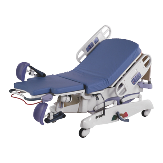
Bed Illustration Siderail Controls (Patient Side) Siderail Controls (Clinical Staff Side) IV Pole Head Board Foot Rest Litter Mattress (1 of 2) Calf Rest Labor Grip (1 of 2) (1 of 2) Fluid Foot Section Basin Locking Bar & Release Foot End Handle Mattress... -
Page 10: Siderail Operation Guide
Siderail Operation Guide OPERATING SIDERAILS To engage the head end siderail, grasp the rail and swing it upward to full height. When the siderail is being raised, it does not lock in the intermediate position. To lower the siderail, push in the release handle and rotate the siderail until it locks in the intermediate position. -
Page 11: Outside Siderail Controls
Siderail Operation Guide OUTSIDE SIDERAIL CONTROLS 1. Press to raise the Fowler (back section). 2. Press to lower the Fowler (back section). 3. Press to raise the litter. 4. Press to lower the litter. 5. Press to raise the foot section. 6. - Page 12 Siderail Operation Guide OUTSIDE SIDERAIL CONTROLS (CONTINUED) 9. Push to lower the head end of the bed (Trendelenburg position). This function is also used for pelvic tilt. NOTE When the bed is at a low height and the Trendelenburg button is pressed, the litter may raise automatically to provide adequate clearance.
-
Page 13: Inside Siderail Controls
Siderail Operation Guide INSIDE SIDERAIL CONTROLS 1. Press to raise the foot section. 2. Press to lower the foot section. 3. Press to raise the Fowler (back section). 4. Press to lower the Fowler (back section). 5. Press to activate the Nurse Call (optional function). 6. -
Page 14: Inside Siderail Controls
Siderail Operation Guide INSIDE SIDERAIL CONTROLS (CONTINUED) 1. Press to turn on the reading light. Press again to turn off the reading light (optional function). 2. Press to turn on the room light. Press again to turn off the room light (optional function). 3. -
Page 15: Pendant Operation Guide
Communication Pendant Operation Guide... -
Page 16: Pendant Operation Guide
Motion Pendant Operation Guide... - Page 17 Motion Pendant with Nurse Call Operation Guide...
-
Page 18: Bed Operation
Bed Operation USING THE BRAKE/STEER PEDALS The brake/steer pedals are located at the center of the base frame on both sides of the bed. To engage the brakes, fully depress the head end side of the pedal. To disengage the brakes, depress the foot end side of the pedal until the pedal is in the neutral (level) position. -
Page 19: Removing The Head Board
Bed Operation REMOVING THE HEAD BOARD To remove the head board, lift it straight up and off the bed. To replace the head board, align the plastic inserts on the bottom of the head board with the slots at the head end of the bed and lower the head board until it completely seats in the slots. -
Page 20: Using The Labor Grips
To use the labor bar, insert it into the sockets located on each side of the litter at the pivot point for the foot pans. The labor bar can be used by the patient to aid with various birthing positions such as squatting or kneel- ing. The optional Stryker labor bar is rated to support 250 pounds. OPTIONAL LUMBAR PILLOW AND PERINEAL WEDGE Use the one−touch lumbar and seat buttons on the siderail to adjust the amount of support given to the... -
Page 21: Removing The Foot Section
As the locking bar is lowered, the gap between the mattresses will narrow to ease installation. The LD304 foot section is designed to lift and support a 300 pound load. OPERATING THE GLIDEAWAY FOOT RESTS/ATTACHABLE CALF SUPPORTS Rotate the foot rest into position by pulling it out and up over the foot end mattress until it clicks into place. -
Page 22: Birthing Bed Positioning
Bed Operation WARNING Prior to placing weight on the foot section, verify the locking bar has been lowered and locked. The foot sec- tion locking bar is not designed for use as a grasping bar or other patient assist device. BIRTHING BED POSITIONING Position the patient’s feet in the foot rests. -
Page 23: Using The Permanently Attached Iv Pole
Bed Operation OPERATING THE 3−STAGE PERMANENTLY ATTACHED IV POLE DETAIL OF I.V. POLE LATCH DETAIL OF I.V. POLE GRIP NOTE The 3−stage, permanently atached IV pole can only be installed at the head end of the bed To use the 3−stage permanently attached IV pole: 1. -
Page 24: Cleaning
Hand wash all surfaces of the bed with warm water and mild detergent. DRY THOROUGHLY. Do not steam clean or hose off the LD304 Birthing Bed. Do not immerse any part of the bed. Some of the internal parts of the bed are electric and may be damaged by exposure to water. -
Page 25: Preventative Maintenance Checklist
Preventative maintenance should be performed at a minimum of annually. A preventative maintenance pro- gram should be established for all Stryker Medical equipment. Preventative maintenance may need to be performed more frequently based on the usage level of the product. -
Page 26: Limited Warranty
If requested by Stryker, products or parts for which a warranty claim is made shall be returned prepaid to Stryker’s factory. Any improper use or any alteration or repair by others in such manner as in Stryker’s judgement affects the product materially and adversely shall... -
Page 27: Return Authorization
Stryker will perform all service during regular business hours (9−5) * Replacement parts and labor for products under PM contract will be discounted. ** Does not include any disposable items, I.V. poles (except for Stryker HD permanent poles), mattresses, or damage re- sulting from abuse. - Page 28 European Representative Stryker EMEA RA/QA Director Stryker France ZAC Satolas Green Pusignan Av. De Satolas Green 69881 MEYZIEU Cedex France 6300 S. Sprinkle Road, Kalamazoo, MI 49001−9799 (800) 327−0770 www.strykermedical.com JH 7/05 4701−009−001 REV D...
Need help?
Do you have a question about the LD304 and is the answer not in the manual?
Questions and answers