Table of Contents
Advertisement
H18 A
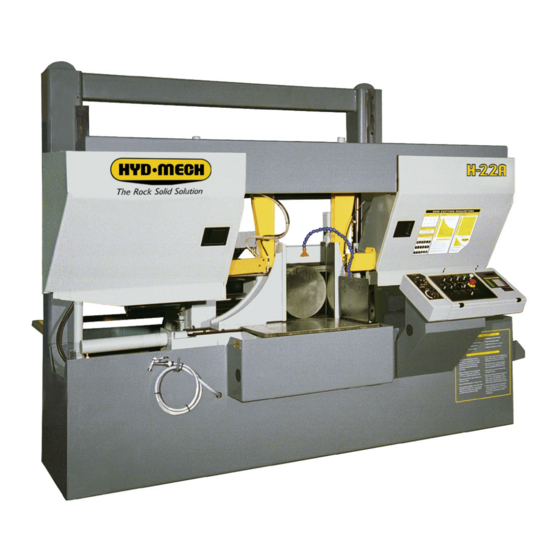
H22 A
&
395598
REV G
THANK YOU,
On behalf of everyone at HYD·MECH Group Limited, we would like to thank and congratulate you on your decision to
purchase a HYD·MECH bandsaw.
Your new machine is now ready to play a key role in increasing the efficiency of your operation, helping you to reduce cost
while boosting quality and productivity.
To ensure you are maximizing the power and versatility of your new HYD·MECH bandsaw, please take the time to
familiarize yourself and your employees with the correct operation and maintenance procedures as outlined in this
manual. Please keep this instruction manual for future reference in a known location and easily accessible to all users of
the device.
HYD·MECH offers a great variety of options, components, and features for its various models. Therefore, some of the
equipment described in this manual (various illustrations and drawings) may not be applicable to your particular machine.
The information and specifications provided in this manual were accurate at the time of printing. HYD·MECH reserves the
right to discontinue or change specifications or design at any time without notice and without incurring any obligation.
Thank you.
Hyd·Mech Group Limited
P.O. Box 1659, 1079 Parkinson Road
Woodstock, Ontario, N4S 0A9
Phone : (519) 539-6341
Service : 1-877-237-0914
Sales : 1-877-276-SAWS (7297)
Fax : (519) 539-5126
e-mail : info@hydmech.com
Printed SEPTEMBER 2014
1
Advertisement
Table of Contents
Troubleshooting

Related Manuals for Hyd-Mech H18 A


Summary of Contents for Hyd-Mech H18 A
- Page 1 H18 A H22 A & 395598 REV G THANK YOU, On behalf of everyone at HYD·MECH Group Limited, we would like to thank and congratulate you on your decision to purchase a HYD·MECH bandsaw. Your new machine is now ready to play a key role in increasing the efficiency of your operation, helping you to reduce cost while boosting quality and productivity.
-
Page 3: Table Of Contents
TABLE OF CONTENTS SECTION 0 - SAFETY INSTRUCTIONS SUMMARY ............................0.1 BASIC RULES ..........................0.3 RESPONSIBILITIES OF THE OWNER ....................0.3 RESPONSIBILITIES OF THE OPERATOR AND MAINTENANCE PERSONNEL ......0.4 SAFETY HAZARD LABELS ......................0.6 SECTION 1 - INSTALLATION SAFETY PRECAUTIONS .........................1.1 LIFTING INSTRUCTIONS ........................1.2 FOUNDATION, LEVELLING AND ANCHORING ................1.3 WIRING CONNECTIONS .........................1.3 EARTH GROUNDING PROCEDURE ....................1.4... - Page 4 BLADE TRACKING ADJUSTMENT ....................3.4 IDLER WHEEL TRACKING ......................3.4 DRIVE WHEEL TRACKING ......................3.5 GEARBOX LUBRICATION (H-18ASV A503 GEARBOX, H-22ASV A603 GEARBOX) ....3.5 OUTPUT SHAFT LUBRICATION .....................3.5 CAM FOLLOWER ADJUSTMENT ....................3.6 LUBRICATION ..........................3.6 HYDRAULIC MAINTENANCE ......................3.7 CLEANLINESS ..........................3.7 TROUBLESHOOTING ........................3.8 PROGAMMABLE LOGIC CONTROL ....................3.10 PLC PARAMETERS ........................3.11 PLC TROUBLESHOOTING ......................3.13 MITSUBISHI FX2N 48MR INPUTS AND OUTPUTS ..............3.18...
-
Page 5: Summary
SECTION 0 - SAFETY INSTRUCTIONS SUMMARY All persons operating this machine must have read and understood all of the following sections of this Manual: Section 0 SAFETY Section 2 OPERATING INSTRUCTIONS However, as a memory aid, the following is a summary of the Safety Section. Put Safety First Mandatory Information –... - Page 6 FOREWORD Put Safety First! This Safety Section contains important information to help you work safely with your machine and describes the dangers inherent to bandsaws. Some of these dangers are obvious, while others are less evident. It really is important to PUT SAFETY FIRST. Make it a habit to consider the hazards associated with any action BEFORE you do it.
-
Page 7: Basic Rules
Manual, and When all operations and procedures are in compliance with this Manual. Hyd-Mech Group cannot accept any liability for personal injury or property damage due to operator errors or non-compliance with the Safety and Operating Instructions contained in this Manual. -
Page 8: Responsibilities Of The Operator And Maintenance Personnel
Define responsibilities Clearly define exactly who is responsible for operating, setting-up, servicing and repairing the machine. Define the responsibilities of the machine operator and authorize him to refuse any instructions by third parties if they run contrary to the machine’s safety. Persons being trained on the machine may only work on or with the machine under the constant supervision of an experienced operator. - Page 9 Clothing, jewellery, protective equipment Personnel operating or working on the machine must not wear un-restrained long hair, loose-fitting clothes and dangling jewellery. When operating or working on the machine, always wear suitable, officially tested personal protective equipment such as safety glasses and safety boots and any other equipment required by plant regulations.
-
Page 10: Safety Hazard Labels
On Hyd-Mech machines the Master Disconnect Switch will be of one of four types: • Rotary switch mounted in electrical control cabinet door and inter-locked with door. - Page 11 MOVING BANDSAW BLADE WILL CUT Do NOT operate with guard removed. Do NOT place hands or fingers near moving bandsaw blade. For blade changing, always follow the proper Blade Changing Procedure, as given in Section 3 of this manual. PINCH POINT Machine parts may move without warning, either because the machine is operating automatically, or because another person initiates the motion.
- Page 12 Item #: 391938 Chip Augar Item #: 391335 Item #: 391340...
- Page 13 Fixed Vise Item #: 391397 Item #: 392801 Shuttle Vise Item #: 392801...
-
Page 15: Section 1 - Installation
MAINTAIN PROPER ADJUSTMENT OF BLADE TENSION, BLADE GUIDES, AND BEARINGS HOLD WORKPIECE FIRMLY AGAINST TABLE. • • DO NOT REMOVE JAMMED CUTOFF PIECES UNTIL BLADE HAS STOPPED. NO MODIFICATIONS TO THE MACHINE ARE PERMITTED WITHOUT PRIOR APPROVAL FROM HYD-MECH. ANY APPROVED MODIFICATIONS SHOULD ONLY BE UNDERTAKEN BY TRAINED PERSONNEL. -
Page 16: Lifting Instructions
LIFTING INSTRUCTIONS... -
Page 17: Foundation, Levelling And Anchoring
FOUNDATION, LEVELLING AND ANCHORING The machine location should be carefully selected. A flat concrete floor area should be chosen. It should have enough free space surrounding the machine to enable free access for safe operation and maintenance. Machine should be leveled in both directions i.e. along and across its in-feed conveyor especially when machine is to be inserted into a larger conveyor system. -
Page 18: Earth Grounding Procedure
EARTH GROUNDING PROCEDURE 1. The customer is to provide and install a ground rod approximately .60 (15mm) diameter, copper clad steel, to be driven no less than 8’ (2.5m) into the ground, no more than 10’ (3m) away from control enclosure. 2. -
Page 19: Section 2 - Operating Instructions
SECTION 2 - OPERATING INSTRUCTIONS This section has been prepared to give the operator the ability to set up the saw for most cutting situations. Before cutting any material, the operator should be familiar with all operations and controls as well as the basic cutting theory described below. - Page 20 FRONT VISE This switch has three positions, OPEN, HOLD and CLOSE. With the switch held in the OPEN position the vise will open all the way or until the switch is released. With the switch in the HOLD position, the vise will stay where it is and will not move freely although it will not resist a large force indefinitely without creeping.
- Page 21 COOLANT This switch has three positions, AUTO, OFF, and ON. In the ON position, the coolant system will operate when there is power to the machine; this allows using the wash gun to clean the machine. In the OFF position, the coolant system is inactive. In the AUTO position the coolant system will only run when the blade is on.
-
Page 22: Plc 100 Control Systems
PLC 100 CONTROL SYSTEMS NOTE: This instruction manual is applicable to the H-18/22 SV equipped with a MITSUBISHI PLC. OPERATION OVERVIEW DISPLAY WINDOW NAVIGATION KEYS ENTER KEY The PLC is a programmable logic controller which allows the operator to run the machine in both manual and automatic modes. -
Page 23: Function Key Descriptions
ACTIVATING THE PLC Position the head, fixed vise, and shuttle vise switches to the NEUTRAL (center) positions. If any of these switches are not in the NEUTRAL position, the hydraulics will not start. The PLC control will become active when the HYDRAULIC START button is depressed and “held in”... -
Page 24: Single Part Cycle Operation
SINGLE PART CYCLE OPERATION In MAN mode, the PLC allows the operator to initiate a “Single Part Cycle” to cut one piece at a desired length. To accomplish this, follow the procedure below. 1. A trim cut should be made before initiating the “Single Part Cycle” operation. 2. -
Page 25: Automatic Operation
AUTOMATIC OPERATION When the AUTO/MAN button is pressed, the red indicator light above it will come on, and the blade will stop if it has been running. The screen will change to the JOB display window as shown below and be ready for editing or starting a new job. All manual functions will be disabled. - Page 26 WORKING WITH A QUEUE The purpose of a QUEUE is to allow the operator to run several jobs (max of 5) in series if they are of the same material and shape. In AUTO mode, press the key below the word “QUE” on the display and the display window will appear as shown. If you choose to VIEW the QUEUE, press the key below the words “VIEW QUE”...
-
Page 27: Shuttle Emergency Stop
SHUTTLE EMERGENCY STOP A second emergency stop push button is mounted to the shuttle above the shuttle vise cylinders. This mushroom button stops the blade and hydraulic motors. Both vises will hold their position but, pressure will begin to fall off. Long pieces of work should always be supported so they will not become loose over time and fall while the machine is shut down. -
Page 28: Cutting Parameters Chart
CUTTING PARAMETERS CHART A full size CUTTING PARAMETERS CHART is mounted on the front of the saw. The chart contains five steps for the operator to follow in order to achieve optimum performance of the saw. These steps are detailed on the following pages. Saw Cutting Parameters Chart CHART EXAMPLE #1 We will use the parameters chart to set up the saw for cutting 8”... - Page 29 STEP 2: SET FEED FORCE LIMIT The Feed Force Limit is the maximum amount of force with which the head is allowed to push the blade into the work-piece. CUTTING SOLIDS For cutting solids, the wider the section, the less FF should be set, to avoid blade overloading. See the graph below. % OF FF SETTING (INDICATED...
- Page 30 STEP 3: DETERMINE OPTIMUM BLADE PITCH - TEETH PER INCH (T.P.I.) Selecting a blade with proper tooth pitch is important in order to achieve optimal cutting rates and good blade life. For cutting narrow or thin wall structural materials a fine blade with many teeth per inch (T.P.I.) is recommended. For wide materials a blade with a coarse pitch should be used.
- Page 31 STEP 4: DETERMINE OPTIMUM BLADE SPEED, V (ft/min) (m/min) The relationship between optimum blade speed and effective material width for various materials is represented on the graph shown. The graph shows that as effective material width gets wider or as material gets harder, lower blade speeds are recom- mended.
- Page 32 The following table gives examples of the optimum blade speeds for different materials. MATERIALS OPTIMUM BLADE SPEED (ft/min) (m/min) 5” (125mm) Diameter Solid Carbon Steel 12” (300mm) I-Beam 4” x 4” (100mm x 100mm) Rect. Tube 1/4” (6mm) Wall 4” (100mm) 400 Stainless Steel 2”...
- Page 33 FEED RATE, continued If the saw is fitted with a blade coarser than optimum (e.g.: 1.4/2.5 TPI) we can still use the graph, but we go to the 1.4/2.5 curve. As a result we find that the FEED RATE is decreased to 1.3 in/min (133mm/min) for this blade. If however, the machine is fitted with a finer than optimum blade (e.g.
-
Page 34: Additional Controls
ADDITIONAL CUTTING SETUP EXAMPLES, continued EXAMPLE # 3 Material: Bundle low carbon steel 2” x 2” Tube with 1/4” wall, 12 piece bundle (50mm x 50mm with 6mm wall) Dimensions: 6” x 8” (150mm x 200mm) Step 1 Effective Material Width: 5” ( .6 X 8” ) 120mm (.6 x 200) Step 2 Feed Force limit setting for 8”... -
Page 35: Head Up And Down Limit Setting
HEAD UP and DOWN LIMIT SETTING The head up limit is used to restrict the distance the head travels for each stroke. It can be adjusted at any time by moving the switch trip plate to any position on the vertical bar. The trip plate & switches are found behind the head on the drive end near the gear box. -
Page 36: Bundling Operation (Option)
BUNDLING OPERATION (OPTION) The bundling vises can be operated in direct conjunction with the front and shuttle vises or at a slower clamping speed. Either bundling can be turned on or off at any time. The on / off valves are shown in the photos. The speed at which the bundling jaws open and close can be adjusted as required by turning the flow control valves (shown in the photos) for each bundling cylinder. -
Page 37: Section 3 - Maintenance
SECTION 3 – MAINTENANCE SAFETY DURING MAINTENANCE AND TROUBLESHOOTING “Lock-out”, or “Lock-out Tag-out” are terms that refer to procedures taken to prevent the unexpected start-up, or other release of energy, by a machine, whenever anyone is required to remove or bypass safety guards or devices, or whenever anyone is required to place part of his body in a hazard area. -
Page 38: Blade Change Mode Procedure
RESTORING MACHINE TO USE After completion of all repairs or maintenance to the locked-out machine, it shall be restored to use as follows: The person(s) who performed the work shall verify that all areas around the machine are safe, before the machine is re-energized. -
Page 39: Blade Removal
BLADE REMOVAL 1. With the blade change mode key switch in ‘OFF’, the blade stopped and the hydraulics ON, raise the saw head until the drive door will clear the electrical control panel. 2. Open the front vise about 12”. This will provide room between the two guide arms to easily grasp the blade with two hands, BUT DO NOT TOUCH THE BLADE UNTIL THE BLADE CHANGE MODE SWITCH IS TURNED TO THE ‘ON’... -
Page 40: Blade Brush Adjustment
BLADE BRUSH ADJUSTMENT The blade brush is properly set when machine leaves the factory, but it wears out during operation and needs to be readjusted periodically. The blade brush assembly is found behind the drive side door and is shown below. To adjust the assembly, loosen the hex nut, turn the setscrew counterclockwise until the wires on the brush touch the bottom of the blade gullets and tighten the hex nut. -
Page 41: Drive Wheel Tracking
DRIVE WHEEL TRACKING Release blade tension before adjusting. Loosening bolts “A” and turning in set screws “C” by equal amounts will move the blade OFF the wheel. Loosening bolts “B” and turning in set screws “D” by equal amounts will move the blade ON to the wheel. -
Page 42: Cam Follower Adjustment
CAM FOLLOWER ADJUSTMENT There are two cam followers mounted on the head frame. The set of cam followers are shown below. One of them is fixed and the other is adjustable. The cam followers are factory set and usually do not require adjustment. In a properly adjusted system of cam followers only one side should be in contact with the guide. -
Page 43: Hydraulic Maintenance
HYDRAULIC MAINTENANCE 1. OIL FILTER- Ten micron filtration of the oil is provided by a spin on type filter mounted on the tank return line. The element should be changed after the first 50 hours of operation and then every 500 working hours. See section 5 for replacement filter element information. -
Page 44: Troubleshooting
TROUBLESHOOTING PROBLEM PROBABLE CAUSE SOLUTION Blade worn. 1a. Replace blade. Low blade tension. 1b. Tension blade. Saw is cutting out of square vertically. Blade guides. Check for worn guides. Excessive feed rate. 1d. Reduce. Saw is cutting out of Stock not square in vises. Adjust accordingly. - Page 45 Reload with stock or reset the blade. Saw starts but will not On machines so equipped, the out- Hold the hydraulic start button and run after Start button has of-stock or blade breakage limit release the blade tension or open vises been released.
-
Page 46: Progammable Logic Control
PROGAMMABLE LOGIC CONTROL Note: The PLC is equipped with a lithium battery to keep the program stored while the power is shut down. The battery will need to be replaced every 3 to 5 years, depending on the usage. A visual warning will be displayed on the interface when the battery drains to a certain level. -
Page 47: Plc Parameters
PLC PARAMETERS SPEED CONST Blade speed adjustment number. If the actual blade speed is different than the displayed blade speed, a new speed factor will need to be calculated (providing the WHEEL TRGETS parameter is set correctly). Actual speed ÷ display + adjustment factor X existing speed factor = New Speed Factor WHEEL TRGETS Number of targets per revolution of the idler wheel. - Page 48 FEED RATE Activates feed rate display. Not active on S20A, S23A and H10 machines. ACTUAL POSITION If this value is set to “YES,” displays shuttle vise actual position. HOLD SHT HOME Hold shuttle VISE home and closed during cut. BRKN PROX Allows user to override signal from proximity sensor in case it is broken.
-
Page 49: Plc Troubleshooting
PLC TROUBLESHOOTING Problem 1 (for automatic models with a shuttle) PLC is not measuring lengths Possible causes: 1. Encoder a. Pinion gear is loose on the encoder shaft b. A bad encoder 2. Encoder Cable a. Bad connections at the encoder or the PLC b. - Page 50 Problem # 2 (for automatic models with a shuttle) Inaccurate Lengths in Auto Mode Possible Causes: 1. Encoder a. Pinion not engaging the rack all the way from front to back. b. Mechanical interference. c. Pinion loose on the encoder shaft. 2.
- Page 51 If the display does not read as specified: • Check the encoder pinion gear to be sure it can run smoothly down the rack and that the gear and rack teeth engage over the entire travel of the shuttle. • Check that the pinion gear is tight on the encoder shaft. •...
- Page 52 Problem 3 Auto Cycle Not Being Completed In auto mode, the PLC controls the saw functions through output relays. For a certain function to be actuated, the PLC must first see specific input(s). Like the output relays, the input relays are located on the PLC unit. Directly beside the input and output terminals are red LED’s (Light Emitting Diode), which will light up when the corresponding input is being received or output being actuated.
- Page 53 FUSES The PLC outputs are protected with four glass fuses which are mounted on TB5(Beside power supply). Fuse “FU8” is a 2 amp instant blow fuse which feeds power to the input side of the PLC thorough input terminal “L” Fuses “FU3”...
-
Page 54: Mitsubishi Fx2N 48Mr Inputs And Outputs
MITSUBISHI FX3U 48MR INPUTS AND OUTPUTS PLC status indicators: POWER On when power exists to the PLC. On when the PLC is in run mode. If not, check the run/stop switch. It should be in the run position. BATT V6 Battery low voltage. -
Page 55: M12 Pin Assignments For I/P & O/P Devices
X0 Shuttle encoder, channel A Shuttle vise close switch X1 Shuttle encoder, channel B Shuttle vise open switch X2 Blade Speed Front vise close switch X3 Feed rate encoder A Front vise open switch X4 Feed rate encoder B Head raise switch X5 Head down L/S (HDN) Head lower switch X6 Coolant Switch... - Page 56 Input/Output Terminal Information Calibration Procedure Length calibration may be achieved in two ways: By inputting the ACTUAL LTH or the LTH CONST parameter. To determine the ACTUAL LTH value, the LTH CLB (length calibration) procedure must be executed. In manual mode, position a piece of material, which is longer than the shuttle full stroke length and close the front vise. Simultaneously press the “FWD”...
- Page 57 Make small adjustments at a time (i.e. .020” - .030”) and check with test cuts. To adjust “LTH CONST”, follow this procedure: Cut length ÷ Programmed length x Existing “LTH CONST” = New “LTH CONST” Example: Cut length of 11.998”, Programmed length of 12”, Existing “LTH CONST” parameter of 0.001256. 11.988 ÷...
-
Page 58: Plc Parameter Definitions & Values
PLC PARAMETER DEFINITIONS & VALUES H-18A, H-22A Parameter Definitions & Values Description Definition Value SPEED CONST Blade speed adjustment number. WHEEL TARGETS Number of targets per revolution of the idler wheel. Can be toggled either 1 or 6. HEIGHT CALIBRATION This is to be used only if calibration is required. -
Page 59: Section 4 - Electrical
SECTION 4 - ELECTRICAL ELECTRICAL SCHEMATICS: SEE PDF ON ATTACHED CD... -
Page 61: Section 5 - Hydraulic
SECTION 5 - HYDRAULIC SYSTEM FOR HYDRAULIC SCHEMATICS AND PLUMBING DIAGRAMS SEE PDF ON ATTACHED CD. The H-18/22 SV hydraulic system does not require any special work on a new machine before its start-up. The hydraulic tank is filled with Texaco Rando HD 46 hydraulic oil and all machine functions have been tested at the factory to ensure proper operation upon initial start-up. -
Page 62: Gland Assemblies
CYLINDER ASSEMBLIES GLAND ASSEMBLIES CYLINDER DIAMETER O RING BACKUP GLAND LOADED WIPER O RING U CAP 2.0” 362960 362785 CS20-GL-01A 362830 363330 2.5” 362970 362790 CS25-GL-01B 362815 363335 3.0” 362985 362795 CS30-GL-01A 362815 363335 3.5” 362995 362800 CS35-GL-01A 362835 363340 4.0”... -
Page 63: Section 6 - Mechanical Assemblies
SECTION 6 - MECHANICAL ASSEMBLIES MECHANICAL ASSEMBLY DRAWINGS & PARTS LIST: SEE PDF ON ATTACHED CD... -
Page 65: Section 7 - Options
SECTION 7 - OPTIONS OPTIONAL ASSEMBLY DRAWINGS: SEE PDF ON ATTACHED CD... -
Page 67: Section 8 - Specifications
SECTION 8 - SPECIFICATIONS H-18 ASV BANDSAW SPECIFICATIONS H-18A SV BANDSAW SPECIFICATIONS Round 18" (457mm) Capacity Rectangular 18"x 18"(457mm x 457mm) Length Control Programmable up to 99 jobs, 5 in Queue Length 19'-2" (5842mm) Blade Width 1 1/2", (41mm) , or optional 1 1/4" ( 32mm) Thickness .050"... -
Page 68: H-22 Asv Bandsaw Specifications
H-22 ASV BANDSAW SPECIFICATIONS H-22A SV BANDSAW SPECIFICATIONS Round 22" (558mm) Capacity Rectangular 22"x 22"(558mm x 558mm) Length Control Programmable up to 99 jobs, 5 in Queue Length 22'-6" (6858mm) Blade Width 2" Thickness .063" (1.6mm) Blade Tension Hydraulic Blade Speed 40 - 300 sf/min (12 - 91 m/min) Blade Guides Carbide inserts (water soluble coolant lubricated) -
Page 69: H18Sv & H22Sv Lifting Instructions
H18SV & H22SV LIFTING INSTRUCTIONS... -
Page 70: H18Sv Layout
H18SV LAYOUT... -
Page 71: H22Sv Layout
H22SV LAYOUT... -
Page 73: Section 9 - Warranty
ORAL, INCLUDING WITHOUT LIMITATION ANY IMPLIED WARRANTIES OF MERCHANTABILITY OR FITNESS FOR A PARTICULAR PURPOSE. This warranty may not be changed, altered, or modified in any way except in writing by Hyd-Mech Group Limited HYD·MECH GROUP LIMITED 1079 Parkinson Road P.O.
Need help?
Do you have a question about the H18 A and is the answer not in the manual?
Questions and answers