Table of Contents
Advertisement
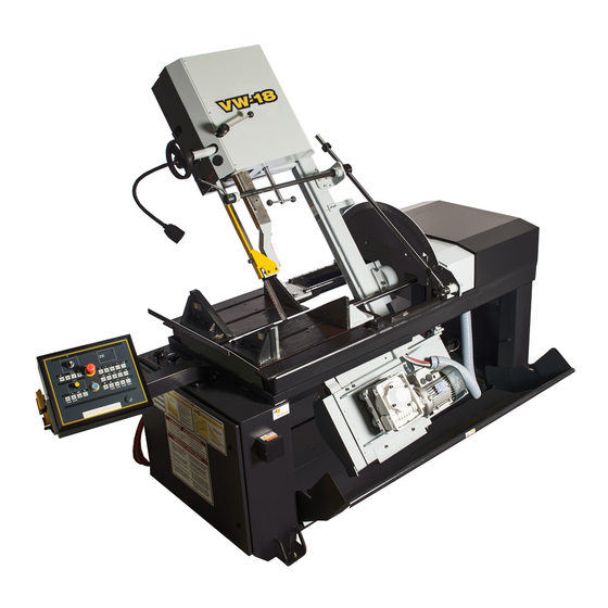
VW-18
REV M
395430
THANK YOU,
On behalf of everyone at HYD . MECH, I would like to thank and congratulate you on your decision to purchase a
HYD . MECH band saw.
Your new machine is now ready to play a key role in increasing the efficiency of your operation, helping you to reduce cut-
ting costs while boosting quality and productivity.
To ensure you are maximizing the power and versatility of your new HYD . MECH band saw, please take the time to famil-
iarize yourself and your employees with the correct operation and maintenance procedures as outlined in this manual.
We sincerely appreciate the confidence you have demonstrated in purchasing our product and look forward to building a
long and mutually beneficial relationship.
Thank-you.
HYD . MECH GROUP LIMITED
P.O. BOX 1030, 1079 Parkinson Road
Woodstock, Ontario Canada, N4S 8A4
Phone: (519) 539-6341
Service 1-877-237-0914
Sales 1-877-276-SAWS(7297)
Fax (519) 539-5126
e-mail, info@hydmech.com
Advertisement
Table of Contents

Related Manuals for Hyd-Mech VW-18


Summary of Contents for Hyd-Mech VW-18
- Page 1 VW-18 REV M 395430 THANK YOU, On behalf of everyone at HYD . MECH, I would like to thank and congratulate you on your decision to purchase a HYD . MECH band saw. Your new machine is now ready to play a key role in increasing the efficiency of your operation, helping you to reduce cut- ting costs while boosting quality and productivity.
-
Page 3: Table Of Contents
BASIC RULES ..........................0.4 RESPONSIBILITIES OF THE OWNER ...................0.5 RESPONSIBILITIES OF THE OPERATOR AND MAINTENANCE PERSONNEL ......0.6 SECTION - 1 INSTALLATION LIFTING AND SHIPPING .........................1.2 LEVELLING THE VW-18 .........................1.2 HYDRAULIC OIL ..........................1.3 CUTTING FLUID ..........................1.3 ELECTRICAL CONNECTION ......................1.3 EARTH GROUNDING PROCEDURE ....................1.4 SECTION 2 - OPERATING INSTRUCTIONS BLADE BASICS ..........................2.1... - Page 4 FOR MECHANICAL ASSEMBLY DRAWINGS SEE PDF ON ATTACHED CD ......6.1 SECTION - 7 OPTIONS FOR OPTIONAL ASSEMBLY DRAWINGS SEE PDF ON ATTACHED CD ........7.1 SECTION 8 - SPECIFICATIONS LIST VW-18 SPECIFICATIONS LIST .......................8.1 VW-18 LAYOUT ..........................8.2 SECTION 9 - WARRANTY WARRANTY .............................9.1...
-
Page 5: Summary
SECTION 0 - SAFETY INSTRUCTIONS SUMMARY All persons operating this machine must have read and understood all of the following sections of this Manual: Section 0 SAFETY Section 2 OPERATING INSTRUCTIONS However, as a memory aid, the following is a summary of the Safety Section. Put Safety First Mandatory Information –... - Page 6 FOREWORD Put Safety First! This Safety Section contains important information to help you work safely with your machine and describes the dangers inherent in our machines. Some of these dangers are obvious, while others are less evident. It really is important to PUT SAFETY FIRST. Make it a habit to consider the hazards associated with any action BEFORE you do it.
- Page 7 Signatures Everyone involved in operation of this machine must sign below to confirm that: I have read and understood all parts of Section 0 – Safety, and Section 2 – Operating Instructions. Name Date Signature Everyone involved in the installation, inspection, maintenance, and repair of this machine must sign below to confirm that: I have read and understood all parts of this Operation and Maintenance Manual.
-
Page 8: Basic Rules
Manual. Hyd-Mech Group cannot accept any liability for personal injury or property damage due to operator errors or non-compliance with the Safety and Operating Instructions contained in this Manual. -
Page 9: Responsibilities Of The Owner
Responsibilities of the owner Organization of work This Operation and Maintenance Manual must always be kept near the machine so that it is accessible to all concerned. The general, statutory and other legal regulations on accident prevention and environmental protection must also be observed, in addition to the Manual material. -
Page 10: Responsibilities Of The Operator And Maintenance Personnel
Responsibilities of the operator and maintenance personnel Safety equipment All machines are delivered with safety equipment that must not be removed or bypassed during operation. The correct functioning of safety equipment on the machine must be checked: • at the start of every shift. •... - Page 11 On Hyd-Mech machines the Master Disconnect Switch will be of one of three types: • Rotary switch mounted in electrical control cabinet door and inter-locked with door •...
- Page 12 Residual Risks The machine is still not completely de-energized if an electrical cabinet door type switch is locked-out. The line side of the disconnect switch itself remains energized. Variable speed blade drives store dangerous voltage in their capacitors, and this requires time to dissipate.
-
Page 13: Section - 1 Installation
SECTION - 1 INSTALLATION SAFETY CONSIDERATIONS All safety precautions must be observed during installation, operation, or repair work on the VW-18 bandsaw ma- chine. Inspect the machine thoroughly before power hook-up. Pay special attention to the electrical and hydraulic sys- tems to ensure no damage was caused in shipping. -
Page 14: Lifting And Shipping
LIFTING AND SHIPPING To lift a VW-18 bandsaw with a forklift, it must meet the following minimum requirements; Capacity of 2800 lb (1270 kg.) at 48”(122 cm) from the mast, as well as 6’ (183cm) long forks. The machine should be lifted from under the base, at either side as shown below. (Head should be at 90º position before... -
Page 15: Hydraulic Oil
HYDRAULIC OIL The VW-18 bandsaw is supplied with Texaco Rando HD46 oil. If it is necessary to change the oil to a different brand, empty the hydraulic tank and fill it approximately 1/3 full with the new brand of oil and operate the saw through several cycles with maximum cylinder extension. -
Page 16: Earth Grounding Procedure
BEFORE START-UP THE FOLLOWING TWO POINTS SHOULD BE CHECKED 1. Signs of damage that may have occurred during shipping to the electrical cables and the hydraulic hoses. 2. The hydraulic oil level is between the upper and lower levels on the gauge. As supplied, the machine is set to run on three phase voltage as indicated on the serial plate and voltage label. -
Page 17: Section 2 - Operating Instructions
START-UP The VW-18 control console has been designed to simplify the operation of the saw so that the operator has the ability to stop any function at any time, and to be able to control all the functions of the saw remotely. -
Page 18: Control Console
CONTROL CONSOLE The operator console has the ability to articulate, and be adjusted for height, to suit the preference of the operator. It is arrayed with a complete set of controls to operate both the hydraulic and electrical functions of the saw. All of the selec- tor switches have to be placed in their neutral center position for the hydraulics to start. -
Page 19: Left Vise
HYDRAULIC START BUTTON: 1. Starts the hydraulic pump motor. 2. Machine disconnect switch must be in “ON” position. 3. The Hydraulic Start button is illuminated whenever the hydraulic pump motor is powered. 4. The head selector switch and vise selector switches have to be in their center, neutral position for hydraulics to start. -
Page 20: Right Vise
RIGHT VISE: RIGHT VISE • This switch operates the vise on the left side of the blade • This selector switch has three positions, OPEN, NEUTRAL and CLOSE. • The switch must be in the NEUTRAL position before the hydraulic system can be started. •... -
Page 21: Cutting Parameters Chart
BLADE SPEED DIAL: This switch controls the blade speed which can be adjusted between 65 and 385 SFPM. The blade speed corresponds to the setting of the dial in relation to the scale. CUTTING PARAMETERS CHART A full size PARAMETERS CHART is mounted on the front of the base. The chart contains five steps for the operator to fol- low in order to achieve optimum performance of the saw. - Page 22 STEP 2 - SET FEED FORCE LIMIT The Feed Force Valve was originally developed as a means to limit maximum feed force, to prevent crooked cuts, espe- cially in wide materials. While it is possible to set the Feed Force Limit low enough that a dull blade would just stall and rub against the work piece, this may result in sluggish feeding.
- Page 23 STEP 4 - DETERMINE OPTIMUM BLADE SPEED, V (ft/min) (m/min) The relationship between optimum blade speed and effective material width for various materials is represented on the graph shown below The graph shows that as effective material width gets wider or as material gets harder, lower blade speeds are recom- mended.
- Page 24 Materials Optimum Optimum Blade Speed Blade Speed ft/min m/min 1 5” (125mm) Dia solid medium carbon steel 2 10” (250mm) I-Beam 3 4” x 4” (100mm x 100mm) Rec tube 1/4” (6mm) wall 4 4” (100mm) 400 stainless steel 5 2” x 2” (50mm x 50mm) Rec tube 1/4” (6mm) wall bundle 5 x 5 pcs 10”...
- Page 25 Feed Rate Calculation Feed Rate for Blade Pitches Other than Optimum Pitch If the saw is fitted with a blade coarser than optimum (e.g... 1.4/2.5 TPI) we can still use the graph, but we go to the 1.4/2.5 curve. As a result we find that the FEED RATE is decreased to 1.3 in/min (133mm/min) for this blade. If however, the machine is fitted with a finer than optimum blade (e.g.
- Page 26 Note: Use this chart when cutting solids. For structurals, see “Cutting Structurals” in step 2. ADDITIONAL CUTTING SETUP EXAMPLES EXAMPLE # 2 Material: Round Steel Tube SAE 4320 - Hardened to 35 RC (325 Bhn) Dimensions - 6” O.D. x 4” I.D. (150mm O.D. x 100mm I.D.) 1.
-
Page 27: Guide Arm Position
Guide arm position wheel Guide arm locking handle. Clockwise to lock, counter clockwise to unlock. Manual head swing GUIDE ARM POSITION In order to obtain maximum cutting performance from the blade, the guide arm should be positioned within 1/2” of the top of the material. -
Page 28: Head Forward & Retract Limit Setting
HEAD FORWARD & RETRACT LIMIT SETTING The Head Retract & Head Forward limit switches are activated by their own respective targets. Each target is factory set. If adjustment is necessary, either target can be loosened and repositioned. The Head Forward target is set to control the distance the blade will advance past the vertical plane of the fixed vise jaw. The target is located on a rail along the left side of the base, near the carriage linear way. -
Page 29: Control Console Position
CONTROL CONSOLE POSITION The control console can be adjusted for height and angular position to suit the operator comfort. It can also be positioned below the table line height for safer loading / unloading of large material, decreasing the likelihood of a collision with the console. -
Page 31: Section 3 - Maintenance & Trouble Shooting
SECTION 3 - MAINTENANCE & TROUBLE SHOOTING LOCK - OUT Purpose: To prevent injury to workers caused by unexpected start-up of machines being worked on. Where the starting of a machine or device may endanger the safety of a worker. Control switches or other control mechanisms shall be locked out;... - Page 32 STEP TWO - Open Doors The blade on the VW - 18 travels around two blade wheels, the bottom Drive wheel and the top Idler wheel. Both of these wheels are housed in compart- ments with locking doors.The photo shows the top Idler wheel with the door open.
-
Page 33: Blade Tracking
BLADE TRACKING Blade tracking should be set so that the blade overhangs the front of each of the wheels by 4.5mm to 5mm, measured from the tip of the teeth to the face of the wheel. Tracking is preset from the factory and normally should not need adjust- ment unless a wheel has been replaced. -
Page 34: Blade Brush Adjustment
HYDRAULIC OIL: The VW-18 is shiopped from the factory with Texaco Rando HD 46 oil. If it is desirable to change brands, the hydraulic system should be drained and thoroughly flushed with the new oil. Recommmended replacement oils:... -
Page 35: Lubrication
See Section 8 Specifications LUBRICATION The VW-18 was designed with a goal to minimize the maintenance required so as to reduce downtime. Moving parts of the VW-18 will require priodic lubrication nonetheless, primarily application of a general-purpose grease to the moveable guide arm, vise ways, and the ilinear bearings. - Page 36 Interupt the main supply to the ma- chine for two or three minutes. If the error returns, call your dealer or con- tact the Hyd-Mech Service Dept. Blown blade motor fuse(s). Check fusing, replace as necessary. Repeated fuse blow-outs indicates an internal wiring fault.
- Page 37 CUTTING AND BLADE TROUBLESHOOTING Saw is cutting out of Blade is worn. Change the blade and check alignment square. with new blade. Blade guide is worn or not Replace the worn guide or adjust the adjusted. guide until the blade is cutting square. Insufficient blade tension Check the blade tension pressure.
- Page 38 Pointer stopped but valve open. 9a. Loosen pointer locknut. Turn the knob rate set at “0”. clockwise to “0”. Tighten locknut. Fast Approach is open. Adjust Fast Approach lever. Contact Blocked lever. your dealer or call Hyd-Mech Service for details.
-
Page 39: Service Records & Notes
SERVICE RECORDS & NOTES DATE SERVICED COMMENTS... -
Page 41: Section 4 - Electrical
GENERAL INFORMATION The machine is supplied for use on a 240V/60HZ supply. If any voltage changes are required, an autotransformer should be used. Consult your Hyd·Mech dealer or Hyd-Mech service department before implementing any changes. INITIAL STARTUP At initial hook-up it is important to check that the phase order is correct. This is indicated by the hydraulic pressure gauge registering a pressure rise. - Page 42 View A Saftey Relay Relays: 1CR, 2CR, 12CR, 20CR FUSE 3FU View B 24 VDC POWER SUPPLY FUSES: 2FU1, 2FU2...
- Page 43 View C BLADE MOTOR VARIABLE FREQUENCY DRIVE View D MOTOR CONTACTOR & O/L ASSEMBLIES FUSE: DISCONNECT SWITCH 1M, 2M,3M & 1 O/L, 2 O/L, 3 O/L 1FU1, 1FU2, 1FU3 D/S 1...
-
Page 44: Section 5 - Hydraulics
SECTION 5 - HYDRAULICS The VW-18 hydraulic system does not require any special work on a new machine before its start-up. The hydraulic tank is filled with Texaco Rando HD 46 oil and all machine functions have been tested at the factory to ensure the proper op- eration upon initial start-up. - Page 45 View C View B View A See Following Pages for Component Views Oil Cooler Directional Valves System Pressure Gauge Hydraulic Manifold View A...
- Page 46 View B Oil Tank Filler Cap & Filter Assembly View C Hydraulic Pump Hydraulic Motor...
-
Page 47: Filler Cap And Filter Element Location
Filler Cap and Filter element Location Filter Insert Pump Access Pressure Adjustment System Pressure Gauge Cleanout Cover Filler Breather... -
Page 48: Oil Level Gauge And Drain Plug
Oil Level Gauge and Drain Plug Oil Level Gauge Oil level should be maintained at the top portion of the level gauge glass window... -
Page 49: Cylinder Assemblies
CYLINDER ASSEMBLIES GLAND ASSEMBLIES CYLINDER BACKUP LOADED DIAMETER O RING O RING GLAND U CAP WIPER 2.0” 362960 362785 CS20-GL-01A 362830 363330 2.5” 362970 362790 CS25-GL-01B 362815 363335 3.0” 362985 362795 CS30-GL-01A 362815 363335 3.5” 362995 362800 CS35-GL-01A 362835 363340 4.0”... -
Page 50: For Hydraulic Schematics And Plumbing Diagrams See Pdf On Attached Cd
For hydraulic schematics and plumbing diagrams see PDF on attached CD. -
Page 52: Section 6 - Mechanical Assemblies
SECTION 6 - MECHANICAL ASSEMBLIES FOR MECHANICAL ASSEMBLY DRAWINGS SEE PDF ON ATTACHED CD... -
Page 54: Section - 7 Options
SECTION - 7 OPTIONS FOR OPTIONAL ASSEMBLY DRAWINGS SEE PDF ON ATTACHED CD... -
Page 56: Section 8 - Specifications List
SECTION 8 - SPECIFICATIONS LIST VW-18 SPECIFICATIONS LIST Capacity (Dimensions given in width x height) Vertical @ 90° Rectangle 18” x 22” 457mm x 559mm Round 18” DIA 457mm DIA @ 45° Rectangle 18” x 14” 457mm x 355mm Round 14”... -
Page 57: Vw-18 Layout
VW-18 LAYOUT... -
Page 60: Section 9 - Warranty
SECTION 9 - WARRANTY WARRANTY Hyd-Mech Group Limited warrants parts/components on each new VW-18 bandsaw to be free from failure resulting from defective material and workmanship under proper use and service for a period of two years following the date of ship- ment to the user.
Need help?
Do you have a question about the VW-18 and is the answer not in the manual?
Questions and answers