Table of Contents
Advertisement
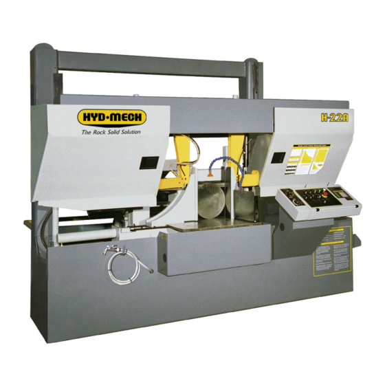
H18A-120
H22A-120
&
Thank you,
On behalf of everyone at HYD·MECH Group Limited, we would like to thank and congratulate you on your decision to
purchase a HYD·MECH bandsaw.
Your new machine is now ready to play a key role in increasing the efficiency of your operation, helping you to reduce cost
while boosting quality and productivity.
To ensure you are maximizing the power and versatility of your new HYD·MECH bandsaw, please take the time to
familiarize yourself and your employees with the correct operation and maintenance procedures as outlined in this
manual.
We sincerely appreciate the confidence you have demonstrated in purchasing our product and look forward to building a
long and mutually beneficial relationship.
Thank you
Hyd·Mech Group Limited
P.O. Box 1659, 1079 Parkinson Road
Woodstock, Ontario, N4S 0A9
Phone : (519) 539-6341
Service : 1-877-237-0914
Sales : 1-877-276-SAWS (7297)
Fax : (519) 539-5126
info@hydmech.com
e-mail :
PRINTED DEC 2013
1
Advertisement
Table of Contents
Troubleshooting

Related Manuals for Hyd-Mech H18A-120


Summary of Contents for Hyd-Mech H18A-120
- Page 1 H18A-120 H22A-120 & Thank you, On behalf of everyone at HYD·MECH Group Limited, we would like to thank and congratulate you on your decision to purchase a HYD·MECH bandsaw. Your new machine is now ready to play a key role in increasing the efficiency of your operation, helping you to reduce cost while boosting quality and productivity.
-
Page 3: Table Of Contents
TABLE OF CONTENTS SECTION 0 - SAFETY INSTRUCTIONS SUMMARY ............................0.1 BASIC RULES ..........................0.3 RESPONSIBILITIES OF THE OWNER ....................0.3 RESPONSIBILITIES OF THE OPERATOR AND MAINTENANCE PERSONNEL ......0.4 SAFETY HAZARD LABELS ......................0.6 SECTION 1 - INSTALLATION SAFETY PRECAUTIONS .........................1.1 FOUNDATION, LEVELLING AND ANCHORING ................1.2 BARFEED INSTALLATION ......................1.2 MACHINE GUARD INSTALLATION ....................1.8 WIRING CONNECTIONS ........................1.10... - Page 4 OPTIONAL ASSEMBLY DRAWINGS: SEE PDF ON ATTACHED CD ..........7.1 POWERED CONVEYOR - CONTROLS ..................7.1 SECTION 8 - SPECIFICATIONS H18A-120 SPECIFICATIONS ......................8.1 H18A-120 MACHINE LAYOUT ......................8.2 H22A-120 SPECIFICATIONS ......................8.3 H22A-120 MACHINE LAYOUT ......................8.4 H22A-120 with OV MACHINE LAYOUT ..................8.5 SECTION 9 - WARRANTY...
-
Page 5: Summary
SECTION 0 - SAFETY INSTRUCTIONS SUMMARY All persons operating this machine must have read and understood all of the following sections of this Manual: Section 0 SAFETY Section 2 OPERATING INSTRUCTIONS However, as a memory aid, the following is a summary of the Safety Section. Put Safety First Mandatory Information –... - Page 6 FOREWORD Put Safety First! This Safety Section contains important information to help you work safely with your machine and describes the dangers inherent to bandsaws. Some of these dangers are obvious, while others are less evident. It really is important to PUT SAFETY FIRST. Make it a habit to consider the hazards associated with any action BEFORE you do it.
-
Page 7: Basic Rules
Manual, and When all operations and procedures are in compliance with this Manual. Hyd-Mech Group cannot accept any liability for personal injury or property damage due to operator errors or non-compliance with the Safety and Operating Instructions contained in this Manual. -
Page 8: Responsibilities Of The Operator And Maintenance Personnel
Define responsibilities Clearly define exactly who is responsible for operating, setting-up, servicing and repairing the machine. Define the responsibilities of the machine operator and authorize him to refuse any instructions by third parties if they run contrary to the machine’s safety. Persons being trained on the machine may only work on or with the machine under the constant supervision of an experienced operator. - Page 9 Clothing, jewellery, protective equipment Personnel operating or working on the machine must not wear un-restrained long hair, loose-fitting clothes and dangling jewellery. When operating or working on the machine, always wear suitable, officially tested personal protective equipment such as safety glasses and safety boots and any other equipment required by plant regulations.
-
Page 10: Safety Hazard Labels
On Hyd-Mech machines the Master Disconnect Switch will be of one of four types: • Rotary switch mounted in electrical control cabinet door and inter-locked with door. - Page 11 MOVING BANDSAW BLADE WILL CUT Do NOT operate with guard removed. Do NOT place hands or fingers near moving bandsaw blade. For blade changing, always follow the proper Blade Changing Procedure, as given in Section 3 of this manual. PINCH POINT Machine parts may move without warning, either because the machine is operating automatically, or because another person initiates the motion.
- Page 12 Item #: 391938 Chip Augar Item #: 391335 Item #: 391340...
- Page 13 Fixed Vise Item #: 391397 Item #: 392801 Shuttle Vise Item #: 392801...
- Page 14 0.10...
-
Page 15: Section 1 - Installation
MAINTAIN PROPER ADJUSTMENT OF BLADE TENSION, BLADE GUIDES, AND BEARINGS HOLD WORKPIECE FIRMLY AGAINST TABLE. • • DO NOT REMOVE JAMMED CUTOFF PIECES UNTIL BLADE HAS STOPPED. NO MODIFICATIONS TO THE MACHINE ARE PERMITTED WITHOUT PRIOR APPROVAL FROM HYD-MECH. ANY APPROVED MODIFICATIONS SHOULD ONLY BE UNDERTAKEN BY TRAINED PERSONNEL. -
Page 16: Foundation, Levelling And Anchoring
X.X =/- 0.5 DEG .X +/- .015 IN DISTRIBUTION OF ANY PART REQUIRES WRITTEN CONSENT Shim OF HYD-MECH GROUP.THIS DATA IS THE PROPERTY OF .XX +/- .010 IN OVERALL DIMENSIONS THIRD ANGLE PROJECTION HYD MECH GROUP AND ITS POSSESION CONFERS NO .XXX +/- .005 IN... - Page 17 2. Move the barfeed into its proper position in relation to the machine. Make sure the lip of the conveyor seals prop- erly with the bead of silicone. 3. Position the mounting holes of the front - end bracket of the barfeed. First fasten the two horizontal hex head bolts (The two socket set screws are used to align the barfeed), and then tighten the two vertical hex bolts.
- Page 18 4. Fill all gaps between the barfeed and machine base with silicone. Fill gaps on both sides of the barfeed. 5. Fasten the drip pan between the barfeed and machine base. Use a sheet of cork to make a gasket for the drip pan.
- Page 19 7. The barfeed support brackets should be fastened once it is levelled and anchored. Brackets 8. The shipping supports must be removed once the barfeed is fastened to the machine. The conveyor support is bolted and tack welded to the table; therefore, the welds must be ground off and the bolts removed in order to disassemble the support.
- Page 20 Two brackets support the shuttle vise for shipping, one on each side of the conveyor. Make sure they are removed before attempting to move the shuttle. Shuttle support brackets 9. Remove the three cable covers that line the barfeed table. Unpack and unravel the cable track holding the wires and hoses for the barfeed shuttle.
- Page 21 11. The M12 connector of wire #23 is to be connected under the gearbox. 12. The two wire connections of the servo motor can now be connected. 13. Connect wire #17, #18, and #19 to the limit switches attached to the shuttle vise frame. Make sure the cover plate is secure and in the proper position.
-
Page 22: Machine Guard Installation
MACHINE GUARD INSTALLATION 15. Position the three pieces of the safety guard around the barfeed. The idler side guard is connected to the ma- chine column by a hex bolt. The drive side guard is connected to the control box by a hex bolt. The rear guard is connected to the rear of the barfeed frame with two hex bolts. - Page 23 16. Fasten the trip wire control box to the safety guard and complete the wire connections (see schematics). The box is attached to the mounting plate with four socket head cap screws. The plate is mounted to the safety guard with two hex bolts.
-
Page 24: Wiring Connections
WIRING CONNECTIONS After the machine is leveled and anchored the necessary power hook-up needs to be performed. In order to provide safe operation as well as to prevent potential damage to the machine, only qualified personnel should make the connections. BEFORE START-UP THE FOLLOWING TWO POINTS SHOULD BE CHECKED: 1. -
Page 25: Section 2 - Operating Instructions
SECTION 2 - OPERATING INSTRUCTIONS This section has been prepared to give the operator the ability to set up the saw for most cutting situations. Before cutting any material, the operator should be familiar with all operations and controls as well as the basic cutting theory described below. -
Page 26: Plc 100 Control System
PLC 100 CONTROL SYSTEM OPERATION OVERVIEW The PLC is a programmable logic controller that allows the operator to run the machine in both manual and automatic modes. All of the machine functions are also controlled from the PLC operator interface. There are four function buttons on either side and eight function buttons below the display. - Page 27 NOTE: If an emergency situation arises during any operation, use the large red mushroom EMERGENCY STOP button located on the control panel to shut down the machine. The PLC operator interface is used in all four operating modes: 1. Manual Mode – permits the operator to control all machine functions using the pushbuttons, as well as the operator interface function keys.
-
Page 28: Manual Mode
SERVICE MODE The SERVICE MODE allows the user to adjust the various PLC parameters. The user will be prompted for a password. Contact Hyd-Mech Group Limited to access this mode. MANUAL MODE Pressing this key will put the saw in MANUAL MODE. - Page 29 PLC Operator Interface and Labeled Buttons MANUAL MODE MANUAL MODE is the default mode. All functions are enabled when in MANUAL MODE. The screen will look as follows:...
-
Page 30: Single Cut Mode Operation
SINGLE CUT MODE OPERATION In MANUAL mode, the PLC allows the operator to initiate a SINGLE CUT MODE to cut one piece at a desired length. Closing the front vise automatically initiates Single Cut Mode. Follow the procedure below. 1. A trim cut should be made before initiating the SINGLE CUT MODE operation 2. -
Page 31: Automatic Operation
AUTOMATIC OPERATION To enter AUTO MODE, the FIXED VISE must be closed, putting the saw in SINGLE CUT MODE. When the AUTO MODE key is pressed, the red indicator will come on. The screen will change to the JOB display window as shown below and will be ready for editing or starting a new job. -
Page 32: Working With A Queue
WORKING WITH A QUEUE The purpose of a QUEUE is to allow the operator to run several jobs (maximum of 5) in series if they are of the same material and shape. To run a QUEUE, it is necessary to program in all job values as is done with programming a single job. After the jobs are programmed in, press QUEUE, press CLEAR to clear the QUEUE, and enter the desired JOB #’s in the desired sequence. -
Page 33: Parameters
PARAMETERS The parameters can be accessed by pressing the service mode button on the panel. These parameters can be changed without a password. - Page 34 PARAMETER DEFINITION Blade Speed Display adjustment number. If actual blade speed is different than SPEED CONSTANT displayed blade speed, a new Speed Constant will need to be calculated. Speed Constant = old Speed Constant x actual speed / displayed speed. Feed rate display constant value.
-
Page 35: Hydraulic Feed Control
HYDRAULIC FEED CONTROL The Hydraulic Feed Control is located to the left of the control panel. These controls allow independent control of Feed Force (FF) and Feed Rate (FR) FEED FORCE KNOB Used to set feed force limit (counterclockwise rotation to increase and clockwise rotation to decrease). -
Page 36: Cutting Parameters Chart
CUTTING PARAMETERS CHART A full size CUTTING PARAMETERS CHART is mounted on the front of the saw. The chart contains five steps for the operator to follow in order to achieve optimum performance of the saw. These steps are detailed on the following pages. Saw Cutting Parameters Chart CHART EXAMPLE #1 We will use the parameters chart to set up the saw for cutting 8”... - Page 37 STEP 2: SET FEED FORCE LIMIT The Feed Force Limit is the maximum amount of force with which the head is allowed to push the blade into the work-piece. CUTTING SOLIDS For cutting solids, the wider the section, the less FF should be set, to avoid blade overloading. See the graph below. % OF FF SETTING (INDICATED...
- Page 38 STEP 3: DETERMINE OPTIMUM BLADE PITCH - TEETH PER INCH (T.P.I.) Selecting a blade with proper tooth pitch is important in order to achieve optimal cutting rates and good blade life. For cutting narrow or thin wall structural materials a fine blade with many teeth per inch (T.P.I.) is recommended. For wide materials a blade with a coarse pitch should be used.
- Page 39 STEP 4: DETERMINE OPTIMUM BLADE SPEED, V (ft/min) (m/min) The relationship between optimum blade speed and effective material width for various materials is represented on the graph shown. The graph shows that as effective material width gets wider or as material gets harder, lower blade speeds are recom- mended.
- Page 40 The following table gives examples of the optimum blade speeds for different materials. MATERIALS OPTIMUM BLADE SPEED (ft/min) (m/min) 5” (125mm) Diameter Solid Carbon Steel 12” (300mm) I-Beam 4” x 4” (100mm x 100mm) Rect. Tube 1/4” (6mm) Wall 4” (100mm) 400 Stainless Steel 2”...
- Page 41 FEED RATE, continued If the saw is fitted with a blade coarser than optimum (e.g.: 1.4/2.5 TPI) we can still use the graph, but we go to the 1.4/2.5 curve. As a result we find that the FEED RATE is decreased to 1.3 in/min (133mm/min) for this blade. If however, the machine is fitted with a finer than optimum blade (e.g.
-
Page 42: Additional Controls
ADDITIONAL CUTTING SETUP EXAMPLES, continued EXAMPLE # 3 Material: Bundle low carbon steel 2” x 2” Tube with 1/4” wall, 12 piece bundle (50mm x 50mm with 6mm wall) Dimensions: 6” x 8” (150mm x 200mm) Step 1 Effective Material Width: 5” ( .6 X 8” ) 120mm (.6 x 200) Step 2 Feed Force limit setting for 8”... -
Page 43: Head Up And Down Limit Setting
HEAD UP and DOWN LIMIT SETTING The head up limit is used to restrict the distance the head travels for each stroke. It can be adjusted at any time by moving the switch trip plate to any position on the vertical bar. The trip plate & switches are found behind the head on the drive end near the gear box. -
Page 44: Bundling Operation (Option)
BUNDLING OPERATION (OPTION) The bundling vises can be operated in direct conjunction with the front and shuttle vises or at a slower clamping speed. Either bundling can be turned on or off at any time. The on / off valves are shown in the photos. The speed at which the bundling jaws open and close can be adjusted as required by turning the flow control valves (shown in the photos) for each bundling cylinder. - Page 45 2.21...
-
Page 46: Section 3 - Maintenance
SECTION 3 – MAINTENANCE SAFETY DURING MAINTENANCE AND TROUBLESHOOTING “Lock-out”, or “Lock-out Tag-out” are terms that refer to procedures taken to prevent the unexpected start-up, or other release of energy, by a machine, whenever anyone is required to remove or bypass safety guards or devices, or whenever anyone is required to place part of his body in a hazard area. -
Page 47: Blade Change Mode Procedure
RESTORING MACHINE TO USE After completion of all repairs or maintenance to the locked-out machine, it shall be restored to use as follows: The person(s) who performed the work shall verify that all areas around the machine are safe, before the machine is re-energized. -
Page 48: Blade Removal
BLADE REMOVAL 1. With the blade change mode key switch in ‘OFF’, the blade stopped and the hydraulics ON, raise the saw head until the drive door will clear the electrical control panel. 2. Open the front vise about 12”. This will provide room between the two guide arms to easily grasp the blade with two hands, BUT DO NOT TOUCH THE BLADE UNTIL THE BLADE CHANGE MODE SWITCH IS TURNED TO THE ‘ON’... -
Page 49: Blade Brush Adjustment
BLADE BRUSH ADJUSTMENT The blade brush is properly set when machine leaves the factory, but it wears out during operation and needs to be readjusted periodically. The blade brush assembly is found behind the drive side door and is shown below. To adjust the assembly, loosen the hex nut, turn the setscrew counterclockwise until the wires on the brush touch the bottom of the blade gullets and tighten the hex nut. -
Page 50: Drive Wheel Tracking
DRIVE WHEEL TRACKING Release blade tension before adjusting. Loosening bolts “A” and turning in set screws “C” by equal amounts will move the blade OFF the wheel. Loosening bolts “B” and turning in set screws “D” by equal amounts will move the blade ON to the wheel. -
Page 51: Cam Follower Adjustment
CAM FOLLOWER ADJUSTMENT There are two cam followers mounted on the head frame. The set of cam followers are shown below. One of them is fixed and the other is adjustable. The cam followers are factory set and usually do not require adjustment. In a properly adjusted system of cam followers only one side should be in contact with the guide. -
Page 52: Hydraulic Maintenance
HYDRAULIC MAINTENANCE 1. OIL FILTER- Ten micron filtration of the oil is provided by a spin on type filter mounted on the tank return line. The element should be changed after the first 50 hours of operation and then every 500 working hours. See section 5 for replacement filter element information. -
Page 53: Troubleshooting
TROUBLESHOOTING Most problems which may occur have relatively simply solutions which appear in this section. If the solution is not found here, contact the Hyd·Mech Distributor from whom you purchased your bandsaw. They have trained field service personnel who will be able to rectify the problem. PROBLEM PROBABLE CAUSE SOLUTION... - Page 54 Reload with stock or reset the blade. Hold Saw starts but will not run On machines so equipped, the out-of- the hydraulic start button and release the after Start button has been stock or blade breakage limit switch blade tension or open vises far enough to released.
-
Page 55: Plc Troubleshooting
PLC TROUBLESHOOTING Problem #1 PLC is not measuring lengths. Possible causes: 1a. Pinion gear is loose on the DRIVE shaft. 1b. A bad Servo Drive. 2a. Damaged PLC hardware. 3a. No power from the PLC unit. Problem #2 Inaccurate Lengths in Auto Mode Possible Causes: 1. - Page 56 Problem #3 Auto Cycle Not Being Completed In auto mode, the PLC controls the saw functions through output relays. For a certain function to be actuated, the PLC must first see specific input(s). Like the output relays, the input relays are located on the PLC unit. Directly beside the input and output terminals are red LED’s (Light Emitting Diode), which will light up when the corresponding input is being received or output being actuated.
-
Page 57: M12 Pin Assignments For I/P & O/P Devices
Problem #4 No Display Possible Causes: 1. No power to the HMI. 2. PLC unit failure. 3. Faulty connection of cable between PLC and Interface. 4. Faulty HMI unit. Diagnosis: a. Check the power LED. This light should be on when the PLC is switched on. b. - Page 58 PCB BOARD: FUSE LOCATION FUSE DESCRIPTION 1 3FU1, 3FU2 5 Amp Time Delay 2 4FU 2 Amp Time Delay 3 5FU1, 5FU2 2 Amp Fast Acting 4 6FU 5 Amp Time Delay 5FU1 5FU2 3FU1 3FU2 COMMUNICATION PLC OUTPUT CABLE CABLE PLC INPUT INPUT CONNECTIONS...
-
Page 59: Standard Parameter Values
STANDARD PARAMETER VALUES Current PARAMETER DEFINITION Value Blade Speed Display adjustment number. If actual blade speed is different than SPEED CONSTANT displayed blade speed, a new Speed Constant will need to be calculated. 70000 Speed Constant = old Speed Constant x actual speed / displayed speed. Feed rate display constant value. - Page 60 STANDARD SERVO PARAMETERS Units MACHINE MODEL H22A-120 Servo 240VAC 480VAC MR-J2S-350A4 PAR. # PAR. DESCRIPTION 0000 Control mode 47280* Electronic gear numerator Electronic gear denominator Pulse In position range Position command acceleration/deceleration Acceleration time constant 1750 Deceleration time constant 1000 S-pattern acceleration/deceleration time constant 0002 Analog monitor output...
-
Page 61: Actual Parameter Values
ACTUAL PARAMETER VALUES Current PARAMETER DEFINITION Value Blade Speed Display adjustment number. If actual blade speed is different than SPEED CONSTANT displayed blade speed, a new Speed Constant will need to be calculated. Speed Constant = old Speed Constant x actual speed / displayed speed. Feed rate display constant value. - Page 62 ACTUAL SERVO PARAMETERS Units MACHINE MODEL H22A-120 Servo 240VAC 480VAC MR-J2S-350A4 PAR. # PAR. DESCRIPTION Control mode Electronic gear numerator Electronic gear denominator Pulse In position range Position command acceleration/deceleration Acceleration time constant Deceleration time constant S-pattern acceleration/deceleration time constant Analog monitor output Parameter block Switch MAIN power OFF, wait 10 sec then switch ON...
- Page 63 Instructions to Synchronize Powered Conveyor with Shuttle To synchronize the Powered Conveyor with the Shuttle, the slow speed is to be synchronized in MANUAL MODE and the fast speed in AUTOMATIC MODE. 1. MANUAL MODE procedure with Shuttle in slow speed 2.
- Page 64 1. AUTOMATIC MODE procedure with Shuttle in fast speed. a) Front Vise must be CLOSED b) Select AUTO MODE on HMI. c) Input a JOB with a length of 600 inches. d) Start the AUTO cycle. e) As the Shuttle starts to move back towards the Powered Conveyor, Close the FEED RATE (Located left of HMI) The Shuttle will stop when it has reached the back position.
- Page 65 3.20...
-
Page 66: Section 4 - Electrical
SECTION 4 - ELECTRICAL ELECTRICAL SCHEMATICS: SEE PDF ON ATTACHED CD... -
Page 68: Section 5 - Hydraulic
SECTION 5 - HYDRAULIC HYDRAULIC SCHEMATICS & PLUMBING DIAGRAMS: SEE PDF ON ATTACHED CD... -
Page 70: Section 6 - Mechanical Assemblies
SECTION 6 - MECHANICAL ASSEMBLIES MECHANICAL ASSEMBLY DRAWINGS & PARTS LIST: SEE PDF ON ATTACHED CD... -
Page 72: Section 7 - Options
SECTION 7 - OPTIONS OPTIONAL ASSEMBLY DRAWINGS: SEE PDF ON ATTACHED CD... -
Page 74: Section 8 - Specifications
SECTION 8 - SPECIFICATIONS H18A-120 SPECIFICATIONS H18A-120 BANDSAW SPECIFICATIONS Round 18" (457mm) Capacity Rectangular 18"x 18"(457mm x 457mm) Length 19'-2" (5842mm) Blade Width 1 1/2", (41mm) , or optional 1 1/4" ( 32mm) Thickness .050" (1.3mm) or optional (.042", 1.1mm) -
Page 75: H18A-120 Machine Layout
H18A-120 MACHINE LAYOUT... -
Page 76: H22A-120 Specifications
H22A-120 SPECIFICATIONS H22A-120 BANDSAW SPECIFICATIONS Round 22" (559mm) Capacity Rectangular 22" (559mm) wide x 22" (559mm) high 6 Cant 20" (508mm) x 22" (559mm) (H x W) Length 22'-6" (6858mm) Blade Width 2" (51mm) Thickness .063" (1.6mm) Blade Tension Hydraulic Blade Speed 40 - 300 sf/min (12 - 91.5 m/min) Blade Guides... -
Page 77: H22A-120 Machine Layout
H22A-120 MACHINE LAYOUT... -
Page 78: H22A-120 With Ov Machine Layout
H22A-120 with OV - MACHINE LAYOUT... -
Page 79: Section 9 - Warranty
ORAL, INCLUDING WITHOUT LIMITATION ANY IMPLIED WARRANTIES OF MERCHANTABILITY OR FITNESS FOR A PARTICULAR PURPOSE. This warranty may not be changed, altered, or modified in any way except in writing by Hyd-Mech Group Limited HYD·MECH GROUP LIMITED 1079 Parkinson Road P.O.
Need help?
Do you have a question about the H18A-120 and is the answer not in the manual?
Questions and answers