Table of Contents
Advertisement
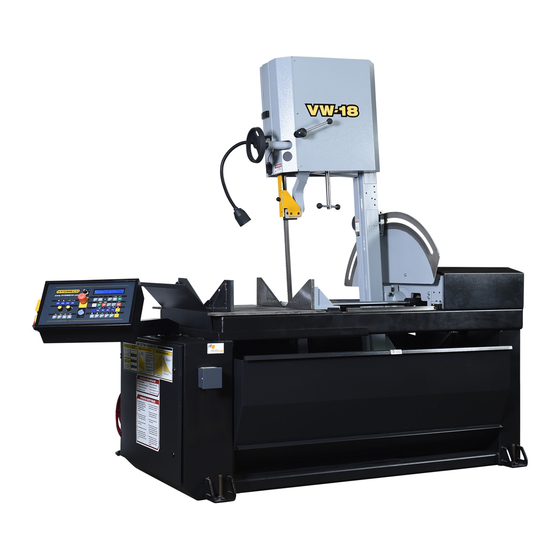
VW18
393349
Valid for machines from serial# JWA0113432B onward
THANK YOU,
On behalf of everyone at HYD·MECH Group Limited, we would like to thank and congratulate you on your decision to
purchase a HYD·MECH bandsaw.
Your new machine is now ready to play a key role in increasing the efficiency of your operation, helping you to reduce cost
while boosting quality and productivity.
To ensure you are maximizing the power and versatility of your new HYD·MECH bandsaw, please take the time to
familiarize yourself and your employees with the correct operation and maintenance procedures as outlined in this
manual. Please keep this instruction manual for future reference in a known location and easily accessible to all users of
the device.
HYD·MECH offers a great variety of options, components, and features for its various models. Therefore, some of the
equipment described in this manual (various illustrations and drawings) may not be applicable to your particular machine.
The information and specifications provided in this manual were accurate at the time of printing. HYD·MECH reserves the
right to discontinue or change specifications or design at any time without notice and without incurring any obligation.
Thank you.
Hyd·Mech Group Limited
P.O. Box 1659, 1079 Parkinson Road
Woodstock, Ontario, N4S 0A9
Phone : (519) 539-6341
Service : 1-877-237-0914
Sales : 1-877-276-SAWS (7297)
Fax : (519) 539-5126
e-mail : info@hydmech.com
Printed March, 2016
1
Advertisement
Table of Contents

Related Manuals for Hyd-Mech VW18


Summary of Contents for Hyd-Mech VW18
- Page 1 VW18 393349 Valid for machines from serial# JWA0113432B onward THANK YOU, On behalf of everyone at HYD·MECH Group Limited, we would like to thank and congratulate you on your decision to purchase a HYD·MECH bandsaw. Your new machine is now ready to play a key role in increasing the efficiency of your operation, helping you to reduce cost while boosting quality and productivity.
- Page 2 BASIC RULES ..........................0.3 RESPONSIBILITIES OF THE OWNER ....................0.3 RESPONSIBILITIES OF THE OPERATOR AND MAINTENANCE PERSONNEL ......0.4 SAFETY HAZARD LABELS ......................0.6 LOCATION OF SAFETY HAZARD LABELS ON VW18 ..............0.8 SECTION 1 - INSTALLATION INSTALLATION ..........................1.1 SAFETY PRECAUTIONS .........................1.1 LIFTING AND SHIPPING .........................1.2 FOUNDATION, LEVELLING AND ANCHORING ................1.2...
- Page 3 MECHANICAL ASSEMBLY DRAWINGS & PARTS LIST: SEE PDF ON ATTACHED CD ....6.1 SECTION 7 - OPTIONS OPTIONAL ASSEMBLY DRAWINGS: SEE PDF ON ATTACHED CD ..........7.1 SECTION 8 - SPECIFICATIONS VW18 SPECIFICATIONS LIST ......................8.1 VW18 LAYOUT ..........................8.2 SECTION 9 - WARRANTY WARRANTY .............................9.1...
-
Page 4: Summary
SECTION 0 - SAFETY INSTRUCTIONS SUMMARY All persons operating this machine must have read and understood all of the following sections of this Manual: Section 0 SAFETY Section 2 OPERATING INSTRUCTIONS However, as a memory aid, the following is a summary of the Safety Section. Put Safety First Mandatory Information –... - Page 5 FOREWORD Put Safety First! This Safety Section contains important information to help you work safely with your machine and describes the dangers inherent to bandsaws. Some of these dangers are obvious, while others are less evident. It really is important to PUT SAFETY FIRST. Make it a habit to consider the hazards associated with any action BEFORE you do it.
-
Page 6: Basic Rules
Manual, and When all operations and procedures are in compliance with this Manual. Hyd-Mech Group cannot accept any liability for personal injury or property damage due to operator errors or non-compliance with the Safety and Operating Instructions contained in this Manual. -
Page 7: Responsibilities Of The Operator And Maintenance Personnel
Define responsibilities Clearly define exactly who is responsible for operating, setting-up, servicing and repairing the machine. Define the responsibilities of the machine operator and authorize him to refuse any instructions by third parties if they run contrary to the machine’s safety. Persons being trained on the machine may only work on or with the machine under the constant supervision of an experienced operator. - Page 8 Clothing, jewelry, protective equipment Personnel operating or working on the machine must not wear un-restrained long hair, loose-fitting clothes and dangling jewelry. When operating or working on the machine, always wear suitable, officially tested personal protective equipment such as safety glasses and safety boots and any other equipment required by plant regulations.
-
Page 9: Safety Hazard Labels
On Hyd-Mech machines the Master Disconnect Switch will be of one of four types: • Rotary switch mounted in electrical control cabinet door and inter-locked with door. - Page 10 MOVING BANDSAW BLADE WILL CUT Do NOT operate with guard removed. Do NOT place hands or fingers near moving bandsaw blade. For blade changing, always follow the proper Blade Changing Procedure, as given in Section 3 of this manual. PINCH POINT Machine parts may move without warning, either because the machine is operating automatically, or because another person initiates the motion.
-
Page 11: Location Of Safety Hazard Labels On Vw18
LOCATION OF SAFETY HAZARD LABELS ON VW18 Power Junction Box Electrical and Hydraulic panel lock. Drive wheel Door Coolant shroud... -
Page 12: Installation
INSTALLATION Upon delivery of your new VW18 saw, it is imperative that a thorough inspection be undertaken to check for any damage that could have been sustained during shipping. Special attention should be paid to the electrical and hydraulic systems to check for damaged cords, hoses and fluid leaks. -
Page 13: Lifting And Shipping
LIFTING AND SHIPPING To lift a VW18 bandsaw with a forklift, it must meet the following minimum requirements; Capacity of 2800 lb (1270 kg.) at 48”(122 cm) from the mast, as well as 6’ (183cm) long forks. The machine should be lifted from under the base, at either side as shown below. -
Page 14: Relocation Of Inner Stop Swing Collars (Power Tilt Option)
RELOCATION OF INNER STOP SWING COLLARS (POWER TILT OPTION) For shipment inner stop swing collars should be relocated and locked against brake assembly as shown on Fig. 1 Inner Collars relocated for Shipment Fig. 1 After installation collars should be moved back to original location against outside collars and locked as shown on Fig. -
Page 15: Cutting Fluid
Check that there is no sign of shipping damage to the electrical conduits, cords or hydraulic hoses. As supplied, the VW18 is built to run on three phase AC Voltage, as indicated on the machine serial plate and voltage label. Machine voltage is customer specific and should be indicated while ordering the machine. If machine voltage does not match available power source contact factory. -
Page 16: Re-Installing The Head Forward/Backward Cylinder And Potentiometer
RE-INSTALLING THE HEAD FORWARD/BACKWARD CYLINDER AND POTENTIOMETER. To prevent damage to the Head cylinder and potentiometer during shipping, the two items have been secured for shipping purposes. For machine operation the head cylinder and potentiometer have to be re-installed as described in the following steps. STEP ONE Remove the top covers of the carriage by removing the front carriage cover first and then the back carriage cover. - Page 17 STEP FOUR Install the back carriage cover and install all the 10-24 SHCS with a 3/16 allen key. Install the front carriage cover and install all the 10-24 SHCS with a 3/16 allen key. View of the head potentiometer and cylinder after re-installation.
-
Page 18: Operator Control Panel
START-UP The VW18 control console has been designed to simplify the operation of the saw, to give the operator the ability to stop any function at any time, and to be able to control all the functions remotely. -
Page 19: Control Console
CONTROL CONSOLE The control console is arrayed with a complete set of controls to operate the electrical and hydraulic functions of the saw. The HMI (Human Machine Interface) consists of all, the electrical controls required to function the saw. STANDARD OPERATOR PANEL POWER TILT OPERATOR PANEL... -
Page 20: Operation Controls (Standard Machine)
OPERATION CONTROLS (STANDARD MACHINE) The electrical buttons on the control panel allow for full manual and semi-automatic operation of the VW18. The operation of each button is detailed on the following pages. BLADE OFF (0) - ON (1): • This selector switch must be in the ON (1) position for the BLADE ON/OFF push-button to function. - Page 21 SERVICE MODE: • Service Mode allows the outputs and inputs to be forced ‘ON’ or ‘OFF’ during trouble shooting. • Prior to forcing any inputs or outputs ‘ON’ or ‘OFF’ care should be taken to ensure a complete under- standing of each ‘INPUT’ and each ‘OUTPUT’ and it’s effect on the operation of the saw. BLADE ON/OFF: •...
- Page 22 MANUAL MODE • Selecting manual mode allows for a manual operation of the saw. • A lit LED will be visible when MANUAL MODE is selected. • In this mode all functions are activated by selection of the respective function buttons on the user interface.
- Page 23 LEFT VISE OPEN: • The push button operates the vise on the left side of the blade. • When depressed and held, the front (saw) vise will open all the way, or until the push button is re- leased. • A pulsing LED will be visible when LEFT VISE OPEN is continuously depressed.
-
Page 24: Manual Mode Machine Operation
HEAD FWD LIMIT: • Depressed when the desired HEAD FORWARD LIMIT SETTING is to be set. • A lit LED will be visible when the HEAD FORTH LIMIT has been reached. HEAD BACK LIMIT: • Depressed when the desired HEAD BACKWARD LIMIT SETTING is to be set •... -
Page 25: Setting Head Forward And Head Backward Limits
Setting Head Forward and Head Backward Limits The machine can be setup to restrict the head movement in Semi-Auto mode between forward and backward limit settings. During normal operating conditions where a complete through cut is required, the head forward limit should be set beyond the material which is to be cut. -
Page 26: Manual Head Swing
PARAMETER DESCRIPTION FACTORY SET VALUE LANGUAGE Language which will be displayed on the interface English MACHINE TYPE Machine type VW 18P MAN & SAD CYCLE Manual and semi automatic PEDAL START Pedal start option INVERTER Inverted blade motor drive BLADE SPD PROXY MINIMAL LUBRIF Machine equipped with low level lubricant sensor for mist coolant... -
Page 27: Machine Alarms And Emergencies
MACHINE ALARMS AND EMERGENCIES The machine’s controller notifies the operator if any alarm or emergency condition which may occur during operation by way of acoustic and visual signals. This section lists the message shown on the display. This message is displayed during the initialization phase after pressing the MACHINE START PRESS RESET key. -
Page 28: Operation Controls (Power Tilt Option)
OPERATION CONTROLS (POWER TILT OPTION) The electrical push buttons on the HMI allow for full manual and automatic operation of the bandsaw. The operation of each push button is detailed on the following pages. BCM: • BLADE CHANGE MODE. • With the selector switch in the OFF position, all functions are operative. •... - Page 29 HEAD FORWARD: • When depressed in MANUAL MODE the head will move forward until any of the following occur: i) The push button is released. ii) Head reaches head forward limit setting. • A lit LED will be visible whilst HEAD FORWARD is depressed. •...
- Page 30 LEFT VISE OPEN: • The push button operates the vise on the left side of the blade. • When depressed and held, the LEFT vise will open all the way, or until the push button is released. • A pulsing LED will be visible when LEFT VISE OPEN is continuously depressed. LEFT VISE CLOSE: •...
- Page 31 CLEAR: When depressed in the following: COUNT • AUTOMATIC MODE: Allows you to delete the angles and replace with new. RESET/CLEAR • MACHINE PARAMETERS: Allows you to delete existing or incorrect data. • Resets the number of pieces cut to 0 (Zero) on the LCD display. RUN / PROG: •In AUTOMATIC MODE: Allows access to vise open/close time and blade parameters.
- Page 32 BLADE STOP: • When depressed the blade will stop. • A lit LED will be visible when the blade is OFF. • Push button is also used to enter the value of 2 when numerical data input is required. BLADE STOP MACHINE STOP: •...
- Page 33 COOLANT AUTO: • When depressed the coolant or mist will flow only when the blade is running OR when the blade is running and the head is descending. This is selectable via the MACHINE PARAMETERS. • A lit LED will be visible when COOLANT AUTO is selected. •...
-
Page 34: Starting The Machine (Power Tilt Option)
SEMI AUTO: • Depress to toggle between MANUAL and AUTOMATIC MODE.(The selected mode will be displayed on the LCD) • A lit LED will be visible when AUTOMATIC MODE is selected. SEMI • Push button is also used to enter a decimal point when numerical data input is required. AUTO HEAD SWING FAST: •... -
Page 35: Cycle Parameter Display (Power Tilt Option)
CYCLE PARAMETER DISPLAY (POWER TILT OPTION) The machine is capable of displaying many parameters, not all of which can de shown on the screen at the same time. Pressing the CYCLE PARAMETERS button will toggle the display of the parameters. The following is a list of available parameters and the corresponding abbreviations as they are shown on the LCD. -
Page 36: Manual Mode: Machine Operation (Power Tilt Option)
Manual mode allows for a manual operation of the saw. In this mode all functions are activated by selection of the respective function buttons on the HMI. Data on the LCD display may differ slightly on the VW18 PT bandsaw. ANGLE GO TO FUNCTION •... - Page 37 • Press COMMAND ENABLE + GO TO (The head will swing to the programmed angle) COMMAND ENABLE CUT IN MANUAL MODE • Open vise/vises • Move Head backwards • Load and position the material to the desired cut length, and then close both vises. •...
-
Page 38: Semi-Automatic Mode: Machine Operation (Power Tilt Option)
• Press COMMAND ENABLE + CYCLE START. COMMAND ENABLE CYCLE START • Use the hydraulic feed controls to adjust the Feed Force Limit and the Feed Rate. The machine will perform the cut and the blade will stop when the head reaches the FORWARD LIMIT position. •... -
Page 39: Cut In Semi-Automatic Mode (Power Tilt Option)
Automatic mode can be programmed to run 2 different cutting angles (Ang. A and Ang. B) 1. Ang. A is to be programmed in Manual Mode first. 2. Ang. B is to be programmed in Semi- Automatic Mode second. CUT IN SEMI-AUTOMATIC MODE (POWER TILT OPTION) In MANUAL MODE position the head to the 1st required angle (Ang. - Page 40 • Press the SEMI AUTO button to go into SEMI-AUTOMATIC MODE. The screen display will change to Semi-Auto Mode. SEMI AUTO # Indicates the next GO TO angle to be executed Angle A Angle B Swing Direction, Swing Direction, Degrees & Minutes Degrees &...
- Page 41 • Select coolant type: FLOOD/MIST and coolant flow: Continuous or Automatic. FLOOD/ COOLANT COOLANT AUTO MIST • Press COMMAND ENABLE + BLADE START. COMMAND ENABLE BLADE START • Use the potentiometer to set the desired blade speed. • Press COMMAND ENABLE + CYCLE START. COMMAND ENABLE CYCLE...
-
Page 42: Machine Parameters (Power Tilt Option)
• Press COMMAND ENABLE + BLADE START. COMMAND ENABLE BLADE START • Press COMMAND ENABLE + CYCLE START. COMMAND ENABLE CYCLE START • The machine will perform the cut for Ang. B. • Once the cut is complete the head will move to the HEAD BACK LIMIT position. •... - Page 43 PARAMETER DESCRIPTION VALUE & PAGE # LANGUAGE Display language ENGLISH (1/46) MACHINE TYPE Machine model VW18PT (2/46) FIPS = Feet, Inch, Pounds, Seconds UNIT OF MEASURE FIPS (3/46) MKS = Meters, Kilograms, Seconds MIST COOLANT OPTION. Is the machine equipped with a mist coolant option? (5/46) CHIP CONVEYOR OPTION.
-
Page 44: º Canted Head
3º CANTED HEAD All VW18 machines are built with the head positioned at a 3º cant. The head can also be positioned at 90º. Positioning the head at any other canted position will cause head vibration which will result in poor cut quality and poor blade life. - Page 45 STEP ONE 90º bolt alignment The head pivot lug contains four SHCS bolts, two on each side. Loosen all the 1/2” SHCS bolts with a 3/8” allen key. 1/2” SCHS bolts 3º canted head alignment Head pivot lug shown at the 3º canted position STEP TWO Turn the HEX STRUT with a 1”...
- Page 46 STEP THREE Block the head so that is does not swing. Remove all three 3/8” HCS bolts with 9/16” flat wrench. Loosen 3/8” SHCS with 5/16 allen key. 3/8” SHCS 3/8” HCS BOLTS Swing Lock Shaft Swing Brake Support Lug Lock Shaft Swing Brake Mounting Bracket...
- Page 47 STEP FIVE 1. Lock the brake in position by moving the locking handle until it is in the position shown. 2. If the locking handle cannot be moved in the position shown, loosen the 3/8 SHCS with 5/16” allen key, adjust handle and lock in position. 3.
- Page 48 STEP SEVEN 1. Loosen the head brake and move head until it is set to 90º as indicated on the scale Scale pointer 2. Ensure the blade is at 90º by using a square to check. If the blade is at 90º...
- Page 49 STEP NINE Clamp sleeve Collar Shafts 1. Swing head to the left until 30º is reached. 2. Loosen both collars with a 3/16 allen key and move towards clamp sleeve hub as shown in the above picture. 3. Tighten both of the collars All the steps are now complete.
-
Page 50: Hydraulic Feed Control
HYDRAULIC FEED CONTROL The Hydraulic Feed Control is located to the left of the control panel. These controls allow independent control of Feed Force (FF) and Feed Rate (FR) FEED FORCE KNOB USED TO SET FEED FORCE LIMIT (COUNTERCLOCKWISE ROTATION TO INCREASE AND CLOCKWISE ROTATION TO DECREASE). -
Page 51: Cutting Parameters Chart
CUTTING PARAMETERS CHART A full size CUTTING PARAMETERS CHART is mounted on the front of the saw. The chart contains five steps for the operator to follow in order to achieve optimum performance of the saw. These steps are detailed on the following pages. Saw Cutting Parameters Chart CHART EXAMPLE #1 We will use the parameters chart to set up the saw for cutting 8”... - Page 52 STEP 2: SET FEED FORCE LIMIT The Feed Force Limit is the maximum amount of force with which the head is allowed to push the blade into the work-piece. CUTTING SOLIDS For cutting solids, the wider the section, the less FF should be set, to avoid blade overloading. See the graph below. % OF FF SETTING (INDICATED...
- Page 53 STEP 3: DETERMINE OPTIMUM BLADE PITCH - TEETH PER INCH (T.P.I.) Selecting a blade with proper tooth pitch is important in order to achieve optimal cutting rates and good blade life. For cutting narrow or thin wall structural materials a fine blade with many teeth per inch (T.P.I.) is recommended. For wide materials a blade with a coarse pitch should be used.
- Page 54 STEP 4: DETERMINE OPTIMUM BLADE SPEED, V (ft/min) (m/min) The relationship between optimum blade speed and effective material width for various materials is represented on the graph shown. The graph shows that as effective material width gets wider or as material gets harder, lower blade speeds are recom- mended.
- Page 55 The following table gives examples of the optimum blade speeds for different materials. MATERIALS OPTIMUM BLADE SPEED (ft/min) (m/min) 5” (125mm) Diameter Solid Carbon Steel 12” (300mm) I-Beam 4” x 4” (100mm x 100mm) Rect. Tube 1/4” (6mm) Wall 4” (100mm) 400 Stainless Steel 2”...
- Page 56 FEED RATE, continued If the saw is fitted with a blade coarser than optimum (e.g.: 1.4/2.5 TPI) we can still use the graph, but we go to the 1.4/2.5 curve. As a result we find that the FEED RATE is decreased to 1.3 in/min (133mm/min) for this blade. If however, the machine is fitted with a finer than optimum blade (e.g.
-
Page 57: Guide Arm Position
ADDITIONAL CUTTING SETUP EXAMPLES, continued EXAMPLE # 3 Material: Bundle low carbon steel 2” x 2” Tube with 1/4” wall, 12 piece bundle (50mm x 50mm with 6mm wall) Dimensions: 6” x 8” (150mm x 200mm) Step 1 Effective Material Width: 5” ( .6 X 8” ) 120mm (.6 x 200) Step 2 Feed Force limit setting for 8”... -
Page 58: Coolant Flow
COOLANT FLOW A generous flow of coolant should be applied in order to increase production and blade life. The machine is provided with a control switch on the opera- tor panel and an independently controlled coolant spout. This spout should always flood the blade with coolant. -
Page 59: Safety During Maintenance
SECTION 3 – MAINTENANCE & TROUBLESHOOTING SAFETY DURING MAINTENANCE “Lock-out”, or “Lock-out Tag-out” are terms that refer to procedures taken to prevent the unexpected start-up, or other release of energy, by a machine, whenever anyone is required to remove or bypass safety guards or devices, or whenever anyone is required to place part of his body in a hazard area. - Page 60 Machine Power Disconnect located on the side of the machine control box. 1. Ensure switch is in the OFF position. 2. Close the disconnect switch cover. 3. Install padlock and lock it. RESTORING MACHINE TO USE After completion of all repairs or maintenance to the locked-out machine, it shall be restored to use as follows: The person(s) who performed the work shall verify that all areas around the machine are safe, before the machine is re-energized.
-
Page 61: Blade Changing Procedure
Switch the blade change mode switch to the ON position and follow lock out procedure. STEP THREE - Open Doors The blade on the VW18 travels around two blade wheels, the bottom Drive wheel and the top Idler wheel. Both of these wheels are housed in compart- ments with locking doors. - Page 62 STEP FIVE - Release Carbides It is necessary to release the carbides from the locked position so that the blade can be easily removed. The carbides are released by loosening the lock nuts and loosening the set screws. STEP SIX - Blade Tension To remove the blade, the blade tension must be released.
-
Page 63: Blade Tracking
BLADE TRACKING Blade tracking should be set so that the blade overhangs the front of each of the wheels by 0.180” to 0.200” (4.5mm to 5mm) measured from the tip of the teeth to the face of the wheel. Tracking is preset from the factory and normally should not need adjustment unless a wheel has been replaced. -
Page 64: Idler Wheel Tracking Adjustment
A new brush has a 3” (76mm) outside diameter. Once worn down to 2.5” to 2” (64mm - 51mm) the brush should be replaced. A brush may be purchased from your HYD-MECH dealer. To replace the brush: 1. Using a 7/8” wrench hold shaft extension ‘B’... -
Page 65: Blade Guides
GEARBOX LUBRICATION The Bonfiglioli W86 gearbox used on the VW18 is supplied with 0.64 liters (0.17 US gallons) of Shell Tivella S 320 synthetic oil. This oil has an ISO Viscosity Grade of 320 that is optimum for ambient temperatures from 20 - 40 Deg C [70 –... -
Page 66: Lubrication
LUBRICATION The VW18 was designed with a goal to minimize the maintenance required so as to reduce downtime. Moving parts of the VW18 will require periodic lubrication nonetheless, primarily application of a general-purpose grease to the moveable guide arm, vise ways, and the linear bearings. -
Page 67: Mep31 And Mep32 Controller: Troubleshooting
1. Coupling loose between gearbox and stepper motor or gearbox and sprocket. 2. Bad stepper motor drive 3. Faulty unit (not repairable in the field) Contact Hyd-Mech service department. 4. Encoder pulley loose. - Check set screw 5. Chain loose or damaged. - Page 68 FUSES MEP31 controller has 2 fuses installed: F1 = 1A 250V and F2 = 2.5A 250V. When the fuse is blown, a lit LED beside the corresponding fuse will be visible. MEP32 controller has 1 fuse installed: F1 = 1A 250V. When the fuse is blown, a lit LED beside F1 fuse will be visible. PROBLEM #2 –...
- Page 69 MACHINE ALARMS AND TROUBLESHOOTING LCD DISPLAY DESCRIPTION DIAGNOSIS EMERGENCY 1.Release EMERGENCY EMERGENCY BUTTON Displayed when the EMERGENCY STOP push button is depressed. STOP PRESSED 2. PRESS RESET PRESS RESET PRESS RESET Displayed at the initialization phase after MACHINE START is depressed. PRESS RESET END OF CUTS Displayed when the machine has completed the number of programmed cuts.
- Page 70 TROUBLESHOOTING THE VW-18 PT PROBLEM PROBABLE CAUSE SOLUTION Shaded actions to be performed ELECTRICAL PROBLEMS only by qualified service personnel. 1 Saw will not start at all. 1.1 Emergency Stop push button not reset. 1.1 Rotate through 45º to pull out E-stop push button.
- Page 71 13.2 Excessive feed force. 13.2 See 6.1 13.3 Wrong blade for work piece material. 13.3 Seek advice o f blade supplier or Hyd-Mech dealer. 13.4 Ineffective cutting fluid. 13.4 Check fluid cleanliness and concentration. Seek advice of fluid supplier or Hyd-Mech dealer.
-
Page 72: Re-Setting 90 Degree Reference Of Angle Encoder (Power Tilt Option)
RE-SETTING 90 DEGREE REFERENCE OF ANGLE ENCODER (POWER TILT OPTION) Main Disconnect switch is located on the side on the machine control box Machine Parameters Machine parameters control the behavior of the machine, the type of optional equipment which, may be installed and the language in which to communicate with the operator. - Page 73 1. Physically set the saw head to true 90 degree reference. 2. Turn the main disconnect switch to the OFF (0) position. 3. Turn the main disconnect switch to the ON (1) position. 4. Press simultaneously and in sequence the MACHINE PARAMETERS and MACHINE START push buttons. (Machine Parameter Mode in effect) To move from parameter to parameter press the ENTER or VERTICAL ARROW button to scroll through the parameters.
-
Page 74: Electrical Schematics: See Pdf On Attached Cd
SECTION 4 - ELECTRICAL ELECTRICAL SCHEMATICS: SEE PDF ON ATTACHED CD... -
Page 75: Hydraulic Schematics & Plumbing Diagrams: See Pdf On Attached Cd
SECTION 5 - HYDRAULIC HYDRAULIC SCHEMATICS & PLUMBING DIAGRAMS: SEE PDF ON ATTACHED CD... -
Page 76: Mechanical Assembly Drawings & Parts List: See Pdf On Attached Cd
SECTION 6 - MECHANICAL ASSEMBLIES MECHANICAL ASSEMBLY DRAWINGS & PARTS LIST: SEE PDF ON ATTACHED CD... -
Page 77: Optional Assembly Drawings: See Pdf On Attached Cd
SECTION 7 - OPTIONS OPTIONAL ASSEMBLY DRAWINGS: SEE PDF ON ATTACHED CD... -
Page 78: Vw18 Specifications List
SECTION 8 - SPECIFICATIONS VW18 SPECIFICATIONS LIST VW-18 II SPECIFICATIONS LIST Straight Head 3º Canted Head Capacity (width x height) Vertical @ 90° Rectangle 18” x 22” 457mm x 558mm 20.75" 457mm x 527mm Round 17.5” diameter 445mm diameter 17.5” diameter... -
Page 79: Vw18 Layout
VW18 LAYOUT... -
Page 80: Warranty
MOTOR, GEARBOX, PUMP, ELECTRIC COMPONENTS, VALVES, HOSES, FITTINGS, and any other items used in the manufacture of the VW18, but not originally manufactured by Hyd·Mech are subject to the original manufacturer’s warranty. Hyd·Mech will provide such assistance and information as is necessary and available to facilitate the user’s claim to such other manufacturer.
Need help?
Do you have a question about the VW18 and is the answer not in the manual?
Questions and answers
how do you set degrees