Table of Contents
Advertisement
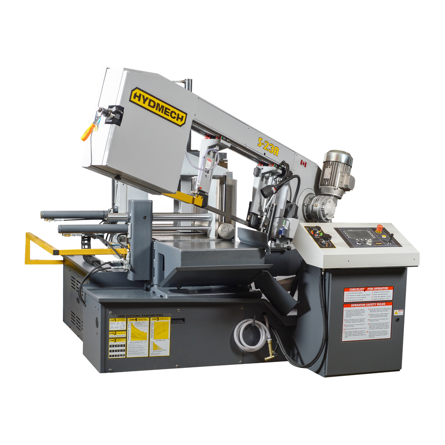
S23A
393359
THANK YOU,
On behalf of everyone at HYD·MECH Group Limited, we would like to thank and congratulate you on your decision to
purchase a HYD·MECH bandsaw.
Your new machine is now ready to play a key role in increasing the efficiency of your operation, helping you to reduce cost
while boosting quality and productivity.
To ensure you are maximizing the power and versatility of your new HYD·MECH bandsaw, please take the time to
familiarize yourself and your employees with the correct operation and maintenance procedures as outlined in this
manual. Please keep this instruction manual for future reference in a known location and easily accessible to all users of
the device.
HYD·MECH offers a great variety of options, components, and features for its various models. Therefore, some of the
equipment described in this manual (various illustrations and drawings) may not be applicable to your particular machine.
The information and specifications provided in this manual were accurate at the time of printing. HYD·MECH reserves the
right to discontinue or change specifications or design at any time without notice and without incurring any obligation.
Thank you.
Hyd·Mech Group Limited
P.O. Box 1659, 1079 Parkinson Road
Woodstock, Ontario, N4S 0A9
Phone : (519) 539-6341
Service : 1-877-237-0914
Sales : 1-877-276-SAWS (7297)
Fax : (519) 539-5126
e-mail : info@hydmech.com
Printed MARCH 2016
1
Advertisement
Table of Contents
Troubleshooting

Related Manuals for Hyd-Mech S23A


Summary of Contents for Hyd-Mech S23A
- Page 1 S23A 393359 THANK YOU, On behalf of everyone at HYD·MECH Group Limited, we would like to thank and congratulate you on your decision to purchase a HYD·MECH bandsaw. Your new machine is now ready to play a key role in increasing the efficiency of your operation, helping you to reduce cost while boosting quality and productivity.
-
Page 4: Table Of Contents
SAFETY HAZARD LABELS ......................0.9 LOCATION AND PART NUMBERS OF SAFETY HAZARD LABELS ..........0.10 SECTION 1 - INSTALLATION SAFETY PRECAUTIONS .........................1.1 LIFTING THE S23A WITH A FORK LIFT ..................1.2 ..................1.3 INSTALLATION OF THE SHUTTLE GUARD FOUNDATION, LEVELLING AND ANCHORING ................1.3 EARTH GROUNDING PROCEDURE ....................1.4 POWER WIRING CONNECTIONS ....................1.5... - Page 5 MECHANICAL ASSEMBLY DRAWINGS & PARTS LIST: SEE PDF ON ATTACHED CD ....6.1 SECTION 7 - OPTIONS OPTIONAL ASSEMBLY DRAWINGS: SEE PDF ON ATTACHED CD ..........7.1 SECTION 8 - SPECIFICATIONS S23A BANDSAW SPECIFICATIONS ....................8.1 S23A BANDSAW LAYOUT .......................8.2 SECTION 9 - WARRANTY WARRANTY .............................9.1...
-
Page 6: Section 0 - Safety Instructions
SECTION 0 - SAFETY INSTRUCTIONS SUMMARY All persons operating this machine must have read and understood all of the following sections of this Manual: Section 0 SAFETY Section 2 OPERATING INSTRUCTIONS However, as a memory aid, the following is a summary of the Safety Section. Put Safety First Mandatory Information –... - Page 7 FOREWORD Put Safety First! This Safety Section contains important information to help you work safely with your machine and describes the dangers inherent in our machines. Some of these dangers are obvious, while others are less evident. It really is important to PUT SAFETY FIRST. Make it a habit to consider the hazards associated with any action BEFORE you do it.
- Page 8 Signatures Everyone involved in operation of this machine must sign below to confirm that: I have read and understood all parts of Section 0 – Safety, and Section 2 – Operating Instructions. Name Date Signature Everyone involved in the installation, inspection, maintenance, and repair of this machine must sign below to confirm that: I have read and understood all parts of this Operation and Maintenance Manual.
-
Page 9: Basic Rules
Manual, and When all operations and procedures are in compliance with this Manual. Hyd-Mech Group cannot accept any liability for personal injury or property damage due to operator errors or non-compliance with the Safety and Operating Instructions contained in this Manual. -
Page 10: Responsibilities Of The Owner
RESPONSIBILITIES OF THE OWNER Organization of work This Operation and Maintenance Manual must always be kept near the machine so that it is accessible to all concerned. The general, statutory and other legal regulations on accident prevention and environmental protection must also be observed, in addition to the Manual material. -
Page 11: Responsibilities Of The Operator And Maintenance Personnel
RESPONSIBILITIES OF THE OPERATOR AND MAINTENANCE PERSONNEL Safety equipment All machines are delivered with safety equipment that must not be removed or bypassed during operation. The correct functioning of safety equipment on the machine must be checked: at the start of every shift. •... - Page 12 Gloves Experience has shown that careless use of gloves around machinery is a major factor in serious hand injuries. Gloves should not be worn when operating or adjusting the machine, except: Wear protective gloves when handling bandsaw blades at blade changes. Gloves may be worn when handling work pieces, only if the machine is in Manual Mode and the bandsaw blade is not running.
- Page 13 On Hyd-Mech machines the Master Disconnect Switch will be of one of four types: • Rotary switch mounted in electrical control cabinet door and inter-locked with door Rotary switch mounted on the side of electrical control cabinet.
-
Page 14: Safety Hazard Labels
SAFETY HAZARD LABELS The safety hazard labels attached to your machine represent important safety information to help you avoid personal injury or death. All supervisors, operators, and maintenance personnel must locate and understand the safety information associated with each hazard label prior to operating or servicing the machine. The safety hazard labels shown below are located at various positions on the machine to indicate possible safety hazards. -
Page 15: Location And Part Numbers Of Safety Hazard Labels
PINCH POINT Machine parts may move without warning because of another person initiating the motion. Keep hands clear of all labeled pinch points, whenever the machine is running. Machine vises and bundling clamps can exert great force and cause severe injury. -
Page 16: Section 1 - Installation
HOLD WORK PIECE FIRMLY AGAINST TABLE • • DO NOT REMOVE JAMMED CUTOFF PIECES UNTIL BLADE HAS STOPPED NO MODIFICATIONS TO THE MACHINE ARE PERMITTED WITHOUT PRIOR APPROVAL FROM HYD-MECH. ANY AP- PROVED MODIFICATIONS SHOULD ONLY BE UNDERTAKEN BY TRAINED PERSONNEL. -
Page 17: Lifting The S23A With A Fork Lift
LIFTING THE S23A WITH A FORK LIFT The S23A is shrink-wrapped and shipped on a pallet. When lifting the pallet with a forklift truck make sure that the load is firmly balanced. The pallet length dimension is 110" (2794 mm). A minimum fork length of 48" (1219 mm) is recommended to safely lift the pallet. -
Page 18: Installation Of The Shuttle Guard
INSTALLATION OF THE SHUTTLE GUARD The shuttle guard of the S23A has been removed for shipping. This guard must be assembled back on to the machine before the POWER WIRING CONNECTIONS are completed. M8 BOLT M12 BOLTS FOUNDATION, LEVELLING AND ANCHORING Machine location should be carefully selected. -
Page 19: Earth Grounding Procedure
EARTH GROUNDING PROCEDURE The customer is to provide and install a ground rod approximately .60 (15mm) diameter, copper clad steel, to be driven no less than 8’ (2.5m) into the ground, no more than 10’ (3m) away from control enclosure. The ground rod is to be connected to customer’s in plant ground system. -
Page 20: Power Wiring Connections
CUTTING FLUID The S23A uses a pump and reservoir to circulate the necessary cutting fluid to the blade for maximum blade life. Your saw blade supplier will be able to provide information to the cutting fluid products that are available for your needs. -
Page 21: Section 2 - Operating Instructions
SECTION 2 - OPERATING INSTRUCTIONS OPERATOR CONTROL PANEL The operator control panel provides the operator with all the controls necessary to operate the saw after the cutting angle has been set and the stock has been loaded and secured. All of the electrical functions are operated from the control panel. -
Page 22: Control Console
CONTROL CONSOLE The control console is arrayed with a complete set of controls to operate the electrical and hydraulic functions of the saw. The HMI (Human Machine Interface) consists of all, the electrical controls required to function the saw. HYDRAULIC FEED CONTROL The hydraulic feed controls are located on the left side of the control console and consist of the Feed Force Setting knob, the Feed Rate knob and the Head Fast Approach lever. - Page 23 EMERGENCY STOP: • This button will stop both the hydraulic and blade motors. The head motion will cease. The vises remain as they are, but if closed, they will lose gripping force. For this reason all long stock should be supported so that it will not fall.
- Page 24 HEAD DOWN: • When the joystick is pulled down the head will move down until any of the following occur: i) The joystick is released. ii) The hydraulic cylinder is at it’s minimum capacity. • Head feed and head force are controlled by the FEED RATE and FEED FORCE controls. HEAD UP: •...
- Page 25 • The pictogram will be yellow in colour when front vise open is selected FRONT VISE ON (Machine Start): • This button on the touchscreen is used on initial start up when “S23A Ready to Operate” is displayed BLADE ENABLE “F6”: • This button is used to enable the blade •...
- Page 26 COOLANT “F2”: • Press F2 continuously until desired COOLANT mode is selected. The pictogram will be changed to yellow when selected. • Coolant Off (White Background) - When selected no coolant will flow • Coolant Manual - When selected Coolant will flow continuously •...
- Page 27 PASSWORD: • This button on the touchscreen is used to enter the password. When the correct password is en- tered then it will allow access to the machine setup, software options, and diagnostic functions of the machine MACHINE SETUP: • This button on the touchscreen is used to access the machine parameters and calibration screens DIAGNOSTIC: •...
-
Page 28: Starting The Machine
STARTING THE MACHINE Turn on the machine disconnect switch to put the machine under power. Release Emergency Stop if depressed When “S23A Ready to Operate” is displayed press the “ON” button on the touch screen Press “Reset Button” If the head is not at the upper L/S then it will move up until the switch is activated Press F5 to home the shuttle You will now be in Manual Mode. -
Page 29: Make A Cut In Manual Mode
SHUTTLE HOME 00000 inch f t/min inch START FRONT VISE STOP SHUTTLE VISE MAKE A CUT IN MANUAL MODE You are now in “Manual Mode” To move the shuttle by joystick, the head must be at the upper L/S. If not the head will move up until the head up L/S is activated. -
Page 30: Execute A Single Job In Automatic Mode
reset LENGTH No. PIECES 999 999 9999 00000 inch 0000 inch f t/min START SHUTTLE VISE FRONT VISE STOP EXECUTE A SINGLE JOB IN AUTOMATIC MODE Press the “Manual Mode” button on the touch screen. You are now in “Automatic Mode Single Job” (Note: The Front Vise must be in the closed position in order to enter Automatic Mode) Move material to the desired length and press vise close buttons. -
Page 31: Execute A Queue Of Jobs In Automatic Mode
PROG PROGRAM LENGTH No. PIECES 100.00 00000 inch 0000 inch f t/min START SHUTTLE VISE FRONT VISE STOP EXECUTE A QUEUE OF JOBS IN AUTOMATIC MODE Press the “Automatic Mode Single Job” button on the touchscreen. You are now in “Automatic Mode Queue” Move material to the desired length and press vise close buttons. - Page 32 reset reset QUEUE Page 1/10 Length No. Pieces Enable Program Part Number 101010 100.0000 300.00 201010 301010 200.0000 401010 400.00 501010 300.0000 Repeat above setup for desired number of jobs. Maximum 10 jobs can be programmed in queue. Press F1 to Reset Queue Press F5 to Reset No.
-
Page 33: Hydraulic Feed Control
HYDRAULIC FEED CONTROL The Hydraulic Feed Control is located to the left of the control panel. These controls allow independent control of Feed Force (FF) and Feed Rate (FR) FEED FORCE KNOB USED TO SET FEED FORCE LIMIT (COUNTERCLOCKWISE ROTATION TO INCREASE AND CLOCKWISE ROTATION TO DECREASE). -
Page 34: Cutting Parameters Chart
CUTTING PARAMETERS CHART A full size CUTTING PARAMETERS CHART is mounted on the front of the main electrical panel. The chart contains five steps for the operator to follow in order to achieve optimum performance of the saw. These steps are detailed on the following pages. - Page 35 STEP 2: SET FEED FORCE LIMIT The Feed Force Limit is the maximum amount of force with which the head is allowed to push the blade into the work-piece. (Feed force to be adjusted during head descent) CUTTING SOLIDS For cutting solids, the wider the section, the less FF should be set, to avoid blade overloading. See the graph below. EXAMPLE: When cutting a solid which is 1/2 of machine capacity using the graph, locate 50% on the horizontal line and travel upwards to the plotted line and then travel directly across to the vertical FF Setting line.
- Page 36 STEP 3: DETERMINE OPTIMUM BLADE PITCH - TEETH PER INCH (T.P.I.) Selecting a blade with proper tooth pitch is important in order to achieve optimal cutting rates and good blade life. For cutting narrow or thin wall structural materials a fine blade with many teeth per inch (T.P.I.) is recommended. For wide materials a blade with a coarse pitch should be used.
- Page 37 STEP 4: DETERMINE OPTIMUM BLADE SPEED, V (ft/min) (m/min) The relationship between optimum blade speed and effective material width for various materials is represented on the graph shown. The graph shows that as effective material width gets wider or as material gets harder, lower blade speeds are recom- mended.
- Page 38 The following table gives examples of the optimum blade speeds for different materials. MATERIALS OPTIMUM BLADE SPEED (ft/min) (m/min) 5” (125mm) Diameter Solid Carbon Steel 12” (300mm) I-Beam 4” x 4” (100mm x 100mm) Rect. Tube 1/4” (6mm) Wall 4” (100mm) 400 Stainless Steel 2”...
- Page 39 FEED RATE, continued If the saw is fitted with a blade coarser than optimum (e.g.: 1.4/2.5 TPI) we can still use the graph, but we go to the 1.4/2.5 curve. As a result we find that the FEED RATE is decreased to 1.3 in/min (133mm/min) for this blade. If however, the machine is fitted with a finer than optimum blade (e.g.
-
Page 40: Section 3 - Maintenance & Troubleshooting
SECTION 3 – MAINTENANCE & TROUBLESHOOTING SAFETY DURING MAINTENANCE AND TROUBLESHOOTING “Lock-out”, or “Lock-out Tag-out” are terms that refer to procedures taken to prevent the unexpected start-up, or other re- lease of energy, by a machine, whenever anyone is required to remove or bypass safety guards or devices, or whenever anyone is required to place part of his/her body in a hazard area. - Page 41 Machine Power Disconnect located on the side of the machine control box. 1. Ensure switch is in the OFF position. 2. Close the disconnect switch cover. 3. Install padlock and lock it. RESTORING MACHINE TO USE After completion of all repairs or maintenance to the locked-out machine, it shall be restored to use as follows: The person(s) who performed the work shall verify that all areas around the machine are safe, before the machine is re-energized.
-
Page 42: Blade Changing Procedure
BLADE CHANGING PROCEDURE Rotate the head about 15° and lift the head up from the table a couple inches to allow enough room to change the blade. NOTE: Wear gloves for protection from the sharp blade. 1. Open the Wheels door by unscrewing the two knobs. 2. - Page 43 4. Remove the worn blade by sliding it off the wheels and out off both guide blocks 5. Your new blade will be in a coil. While wearing gloves, hold the blade away from yourself; twist the blade to uncoil it.
-
Page 44: Blade Tracking Adjustment
9. With the blade in place, turn the tensioner handle clockwise until Bade Tension Display shows required value. Recommended blade tension is between 2600 - 3000 lbs (1180 - 1360 kg) If blade is under tensioned the blade motor will not start. 10. -
Page 45: Drive Wheel Adjustment
DRIVE WHEEL ADJUSTMENT The Drive Wheel adjustment is closely linked to adjustment of the Idler Wheel. The purpose of the adjustment is to ensure that the back of the blade remains about 0.58” - 0.62” (14.7 - 15.7 mm) away from the back edge of the wheel during rota- tion. -
Page 46: Carbide Replacement
CARBIDE REPLACEMENT The blade guide blocks are equipped with one top carbide and two side carbide inserts each. They can be replaced by removing the screws as shown. BLADE BRUSH ADJUSTMENT The machine leaves the factory with the blade brush adjusted for maximum life of the brush. This setting places the ends of the blade brush wires so as to contact the blade at the bottom of the blade gullets. -
Page 47: Angle Brake Adjustment
As shown, there are two springs on socket head screws holding the brush assembly against the blade. There is also an adjusting stop socket set screw A with a hex nut C on it. This adjusting set screw works as a stop determining the brush position in respect to the blade. -
Page 48: Blade Tension Slide Adjustment
BLADE TENSION SLIDE ADJUSTMENT To reduce the play, which may develop over time between the blade tensioner slide and slide gibs, adjust the screws be- tween the gibs and slide as follows: 1. Remove the head front cover. 2. Undo blade tension. 3. -
Page 49: Lubrication
The S23A was designed to minimize the maintenance requirements. Moving assemblies and contact faces need lubrica- tion on a regular schedule whether they are in heavy use or not. The lubrication requirements of the S23A are primar- ily the saw pivot points and shuttle assembly which are equipped with grease fittings, and metal to metal surfaces that require lubrication to prevent wear and seizure. - Page 50 Runner Block Runner Block Guide Arm (2) Guide Arm (2) Runner Block Shuttle Jaw (3) Front Vise/Bundling Shuttle Bundling (4) 3.11...
-
Page 51: Gearbox Lubrication
GEARBOX LUBRICATION The machine is equipped with a worm gear which is permanently lubricated and therefore maintenance free. The box has no filler cap, or drain, as it already contains the correct quantity of synthetic oil, guaranteeing perpetual lubrication of the crown and worm gear. -
Page 52: Troubleshooting
LENGTH INACCURACIES POSSIBLE CAUSES: 1. Coupling loose between screw and stepper motor. 2. Bad stepper motor drive 3. Faulty unit (not repairable in the field) Contact Hyd-Mech service department. 4. Improper Programmed Information: • Length compensation • Existing parameter(s) incorrect • Incorrect blade kerf GENERAL RULES –... -
Page 53: Machine Alarms
MACHINE ALARMS AL1: Emergency: one or more errors occurred: AL6: Emergency push button or emergency unit engaged: these alarms are usually displayed at startup, when emergency push button is pressed or safety relay activated. AL12: Safety blade cover open: blade guard is opened. AL16: Forward software limit switch above start position: this alarm is displayed usually in Manual mode when starting a cut with the head not engaging upper limit switch. -
Page 54: Section 4 - Electrical
SECTION 4 - ELECTRICAL ELECTRICAL SCHEMATICS: SEE PDF ON ATTACHED CD... -
Page 55: Section 5 - Hydraulic
SECTION 5 - HYDRAULIC HYDRAULIC SCHEMATICS & PLUMBING DIAGRAMS: SEE PDF ON ATTACHED CD... -
Page 56: Section 6 - Mechanical Assemblies
SECTION 6 - MECHANICAL ASSEMBLIES MECHANICAL ASSEMBLY DRAWINGS & PARTS LIST: SEE PDF ON ATTACHED CD... -
Page 57: Section 7 - Options
SECTION 7 - OPTIONS OPTIONAL ASSEMBLY DRAWINGS: SEE PDF ON ATTACHED CD... -
Page 58: Section 8 - Specifications
SECTION 8 - SPECIFICATIONS S23A BANDSAW SPECIFICATIONS S23A BANDSAW SPECIFICATIONS Rectangular 16" (405mm) high x 20" (505 mm) wide Capacity - 90º Round 16" (405mm) dia Rectangular 16" (405mm) high x 14" (355mm) wide Capacity - 45º Round 14" (355mm) dia Rectangular 16"... -
Page 59: S23A Bandsaw Layout
S23A BANDSAW LAYOUT... -
Page 60: Section 9 - Warranty
MOTOR, GEARBOX, PUMP, ELECTRIC COMPONENTS, VALVES, HOSES, FITTINGS, and any other items used in the manufacture of the S23A, but not originally manufactured by Hyd·Mech are subject to the original manufacturer’s warranty. Hyd·Mech will provide such assistance and information as is necessary and available to facilitate the user’s claim to such other manufacturer.
Need help?
Do you have a question about the S23A and is the answer not in the manual?
Questions and answers
What to do when you see al4 on screen
What to do when al4 shows on screen