Table of Contents
Advertisement
Quick Links
CHRONO Series
8 and 16 Channel Digital
Video Recorders
• Highly efficient H.264 compression
• Built-in Data Redundancy
• Real-time recording and real-time playback
• System Setup Wizard and User Friendly GUI
• Multi-Resolution recording
• 4 Spot Output (16 Channel Version)
• Highly efficient and stable proprietary Database Structure
• Identical GUI for DVR and client viewer
• Built-in Point-of-Sales support
• Web Client & CMS (Central Management Software) Included
• iPhone Client
Advertisement
Table of Contents

Related Manuals for Vitek CHRONO


Summary of Contents for Vitek CHRONO
- Page 1 CHRONO Series 8 and 16 Channel Digital Video Recorders • Highly efficient H.264 compression • Built-in Data Redundancy • Real-time recording and real-time playback • System Setup Wizard and User Friendly GUI • Multi-Resolution recording • 4 Spot Output (16 Channel Version) •...
-
Page 2: Preface
Preface We welcome you as a new user of the world's best digital video recorder (DVR), and the leading Digital Video Surveillance System. For effective usage, please read this manual carefully. For future reference, please keep this manual close to hand. Copyright/Authentication/Trademark/Limited Warranty Copyright This manual is produced under copyright law. - Page 3 Risk of death or serious injury. This is the highest priority danger warning. • RISK OF EXPLOSION IF BATTERY IS REPLACED BY INCORRECT TYPE. DISPOSE OF USED BATTERY ACCORDING TO THE INSTRCTIONS. • THIS EQUIPMENT IS INDOOR USE AND ALL THE COMMUNICATION WIRINGS ARE LIMITED TO INSIDE OF THE BUILDING.
- Page 4 Risk of minor injury or damage. • If a foreign substance is stuck to the product, remove it using a soft cloth or tissue. Do not use chemical agents (thinner, solvent, etc.) to remove the substance. • Do not operate or store the product in the following places. - An area that is either too cold or too hot - An area of high humidity, or in front of an air-conditioner, or in places subject to sudden temperature changes...
-
Page 5: Table Of Contents
Contents Preface ....................1 Copyright/Authentication/Trademark/Limited Warranty ..........1 Cautions ........................1 Contents..................... 4 Chapter 1. Introduction ..............6 1. The System ......................6 2. General Features ....................6 3. Specification ....................... 7 Chapter 2. System Installation ............9 1. Package Contents ....................9 2. - Page 6 2-5-3. MENU > NETWORK > Notification ............34 2-5-4. MENU > NETWORK > Transmission ............34 2-6. EVENT ......................35 2-6-1. MENU > EVENT > Sensor ............... 35 2-6-2. MENU > EVENT > Motion ............... 36 2-6-3. MENU > EVENT > Video Loss..............38 2-6-4.
-
Page 7: Chapter 1. Introduction
Chapter 1. Introduction 1. The System This product is the one that you are looking for quite long time. Eventually, The DVR which is high performance real time DVR based on H.264, you can enjoy the full benefit of latest compression H.264 and be free from headache because of stability of the DVR. -
Page 8: Specification
3. Specification Model 4 Channel Premium DVR 4 BNC Video 1VGA,& 1 BNC Main, 1 Spot Output 4 RCA (Line-In) Audio 1 RCA (Line-Out) Sensor In 4 TTL Device Alarm Out 2 Relay + 2 TTL I/O Interface RS232, RS485, USB2.0 x 1, USB1.1 x 1 for Mouse Speed Real Time Display... - Page 9 Model 8 Channel Premium DVR 16 Channel Premium DVR 8 BNC 16 BNC Video 1VGA,& 1 BNC Main, 4 Spot Output 8 RCA (4 Mic in, 4 Line in) 16 RCA(4 Mic in,12 Line in) Audio 1 RCA (Line Out) Sensor In 8 TTL 16 TTL...
-
Page 10: Chapter 2. System Installation
Chapter 2. System Installation 1. Package Contents The following components are included in the product: DVR Unit DC Adaptor Power Cord (User's Manual & Network S/W) Remote Controller Quick Guide... -
Page 11: Connecting Devices
2. Connecting Devices 2-1. 4 Channel Premium DVR The rear panel of the 4 channel premium DVR comprises the following: • Front USB: Two USB ports are provided to connect external devices like HDD, Flash memory for Backup, System upgrade or USB mouse on the front panel. A USB mouse can be connected only front panel USB port dedicated only for mouse. - Page 12 • RS-232C: An RS-232C connector is provided to connect an ATM or POS machine for Text-In function. Use a cable with a DB9 (female) connector to connect to the DVR. • Network: Connect a Cat5 cable with an RJ-45 connector to the DVR connector for remote Chapter 3-2.
-
Page 13: 8/16 Channel Premium Dvr
2-2. 8/16 Channel Premium DVR The rear panels of the 6/18 channel premium DVR comprise the following: [8 Channel Premium Model] [16 Channel Premium Model] Video Input Connect the coaxial cables from the cameras to the BNC video connectors. Loop-Through Video Connect the coaxial cables from the Loop BNC connector to another device. - Page 14 • Audio Out: The DVR does not have amplified audio output, so you will need a speaker with and amplifier. • RS-232C: An RS-232C connector is provided to connect an ATM or POS machine for Text-In function. Use a cable with a DB9 (female) connector to connect to the DVR. •...
-
Page 15: Cautions
3. Cautions • Avoid installing the product where there are direct rays or it is hot by locating near from heat generator. (May cause fire) • Do not put vase, flowerpot, cup, cosmetics, drug, and anything the contain water on product. (May cause fire or electric shock, and it may injure people by falling) •... -
Page 16: Chapter 3. Using Dvr
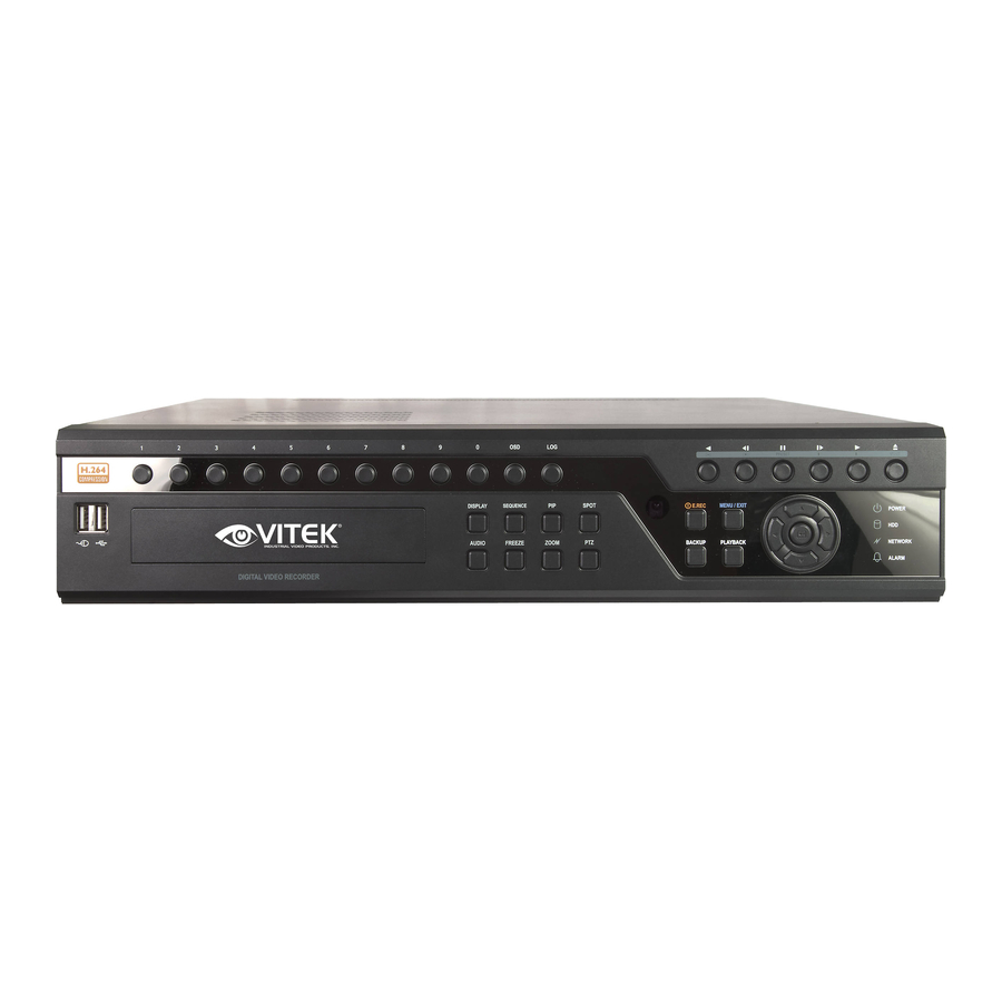
Chapter 3. Using DVR 1. Basic Operation 1-1. Front Panel & IR Remote Controller The DVR should be correctly installed before proceeding. The location and the shape of the buttons may vary depending on the DVR model. (In 4-channel DVR, Only some of main buttons most commonly used can be found on the front panel.) Control Description... -
Page 17: Turning On The System
move down when setting the menu. - Zoom In under PTZ mode. It will open or close the backup drive such as CD-RW or DVD EJECT Button - Display menu to load PTZ presets under PTZ mode. PTZ Button Changes to the PTZ control mode from the live mode. ZOOM Button Zooms the current image on the screen. -
Page 18: Display Icons
Turns on when the system is connected to the network. Turns on when the Alarm is being activated. Mirroring mode E.REC (Emergency Recording) Mode. Displays date & time. IR Remote Controller 1-4. Display Icons No Recording Recording (Red) E.REC (Emergency Recording) Event Recording (Red) Pre Event Recording (Blue) Motion Detection... -
Page 19: User Or Admin Login
1-5. User or Admin Login Press MENU to enter main menu screen. Login in screen appears to enter ID (Administrator or User) and Password. Password can be set up to 8 numbers by the combination of numbers from 0 to 9. The factory default password is ‘none’ so press OK to log in to the system for a first time log in. - Page 20 Address DDNS NETWORK Notification Transmission Sensor Motion EVENT Video Loss Text-In System LOGOUT SHUTDOWN...
-
Page 21: Contextual Menu
1-7. Contextual Menu Additional Contextual Menu screen appears by pressing right button on the Mouse. Layout option allows changing Camera on the monitor. Select preferred camera display option on the monitor. Camera : Select camera no. Layout : Select display mode (8/16 ch. DVR Only) : Select OSD display option Text-In Info.: On/Off Text-In OSD. -
Page 22: Dvr Configuration
2. DVR Configuration 2-1. SYSTEM Under SYSTEM menu, System configuration options for general Information, Date &Time, User, Quick Setup and System Log can be selected. 2-1-1.MENU>SYSTEM>Information In the Information screen, DVR Name, System Version, Upgrade, Mac Address and Configuration options can be selected. Highlight and press DVR Name to enter or change DVR name. -
Page 23: Menu > System > Date & Time
2-1-2. MENU > SYSTEM > Date & Time In the Date & Time, Time Zone, Date, Time, NTP Server, Holiday options can be selected. Highlight and press Time Zone to select right Time Zone. Select ‘Use Daylight Saving Time’ if it is applicable. -
Page 24: Menu > System > Quick Setup
User Name: Enter a user name Group: Select a Group which a new user will belong to Password: Set a new password or change a password. Note : DO NOT have to enter Current password when setting password for the first time as there is no default password for Administrator/User. -
Page 25: Menu > System > System Log
2-1-5. MENU > SYSTEM > System Log In the System Log, full list of system logs can be searched. Press Reload button to refresh log list. USE button to search log list page by page. Log list can be export in txt format. -
Page 26: Device
2-2. DEVICE Under Device menu, Device configuration options for Camera, Audio, Alarm, Keyboard and RS232 & RS485 (POS/PTZ) can be selected. 2-2-1. MENU > DEVICE > Camera Set Camera display option. Camera display (video loss display) can be disabled by unmarking the box next to it if there is no camera connected. -
Page 27: Menu > Device > Audio
Covert Setting Covert setting allows the privacy on monitoring. If Covert is set, live image will not be displayed. Covert can be scheduled by day, time and mode by cameras. Covert Low Mode: No display of video image on screen but OSD still remains on screen. Covert High Mode: Neither of video image or OSD will be displayed on screen. -
Page 28: Menu > Device > Keyboard
2-2-4. MENU > DEVICE > Keyboard Press to find and select keyboard from the list. 2-2-5. MENU > DEVICE > RS232 & RS485 Press to select a device for each ports. RS232: Supports Text In (POS) device. PTZ and Keyboard RS485: Supports Text In (POS) device ,PTZ and Keyboard. -
Page 29: Display
2-3. DISPLAY Under Display menu, Display configuration options for OSD and Monitor can be selected. 2-3-1. MENU > DISPLAY > Display Language: Select system language. Press to find available language options. Hide Status Bar: Select On/Off and time to hide Status Bar when system is not in use. OSD margin: Set OSD margin (position) using Freeze: Display an image in either Field or Frame format when it is in still (freeze) mode. -
Page 30: Menu > Display > Monitoring
2-3-2. MENU > DISPLAY > Monitoring Event Pop-up: Pops up the camera image in full screen when pre-set event occurs. Sequence Interval: Set time interval between cameras under sequence mode. Event Pop-up: Pops up the camera image in full screen on spot monitors when pre-set event occurs. -
Page 31: Record
2-4. RECORD Under Record menu, Record configuration options for Storage, Record and Record Tools can be selected. 2-4-1. MENU > RECORD > Storage In Storage, it displays the installed/connected storage status such as Capacity, Type, Usage and Status. Format: Press Format to format selected HDD. Record: Displays the recording period and data stored on HDD. -
Page 32: Menu > Record > Record
2-4-2. MENU > RECORD > Record In Record, general recording options can be selected including overwrite, resolution, speed, recording quality and etc. Overwrite: Select Overwrite to overwrite recorded HDD data when it is full. Audio Record: Select Audio Record to record audio with video image. Resolution: Select recording resolution. -
Page 33: Menu > Record > Record Tools
Setting to set recording options. Use Default Setting: Check Use Default Setting to follow main recording setting under Record menu. 2-4-3. MENU > RECORD > Record Tools In Record Tools, estimated HDD usage and recording period can be calculated. Press Calculate once resolutions, ips, number of cameras and quality are set. -
Page 34: Network
2-5. NETWORK Under Network menu, Network configuration options for network Address, DDNS, Remote Notification and Transmission can be set up. 2-5-1. MENU > NETWORK > Address In Address, Information such as Type, IP address, Subnet Mask, Gateway Port and DNS can be set for network connections. -
Page 35: Menu > Network > Notification
2-5-3. MENU > NETWORK > Notification In Callback, set up IP addresses of client sites so that Events detected in local system can be notified to multi remote client sites simultaneously. Enter IP addresses of client sites to receive events notifications on remote sites. -
Page 36: Event
2-6. EVENT Under Event menu, events can be set in synchronization with Sensor, Motion, Video Loss, Text-In, System, 2-6-1. MENU > EVENT > Sensor In Sensor, each sensor can be selected for activation and its type. Select Sensor Type using button. -
Page 37: Menu > Event > Motion
PTZ can be sync with Event using its preset function. If Event occurs, PTZ moves to the position where event and positions are pre set. The above menu shows, Sensor 1 is set to sync to cameras 2,3,4 and 5. If you click PTZ section, PTZ preset (position) can be set for cameras in the event of Sensor activation. - Page 38 In Record, each camera can be synchronized with single and multi motion detections from other cameras. Press to select cameras to be synchronized with motions detections. In Alarm, each camera with motion can be synchronized with single and multi alarms. Press to select alarms to be synchronized with cameras for motion events.
-
Page 39: Menu > Event > Video Loss
2-6-3. MENU > EVENT > Video Loss In Video Loss, single or multi cameras can be synchronized for event recording when there is a video loss. Press to select single or multi cameras to be synchronized with cameras for video loss. In Alarm, each camera with video loss can be synchronized with single and multi alarms. -
Page 40: Menu > Event > Text-In
2-6-4. MENU > EVENT > Text-In The system allows Text In from POS/ATM machines. Note : For use of POS/ATM, the system must support general ASCI code. Text-In Model: Select Text-In model from the list Transaction Begin: Enter a word which the transaction info to be displayed on screen as a start. Any Character: Check Any Character to start display a text with any character as a start. -
Page 41: Menu > Event > System
In Notification, text event can be synchronized with single and multi callback or emailing sites. Press to enter callback or email address to be synchronized with text event. 2-6-5. MENU > EVENT > System In System, S.M.A.R.T function monitors storage conditions such as Temperature, Conditions and Recording. -
Page 42: Playback
3. Playback The system provides various playback menu to search recorded data. Please click right Mouse button on Search Mode and select the storage type. If backup data is selected, the data on external HDD can be searched. Camera : Select camera no. Layout : Select display mode (8/16 ch. -
Page 43: Go To Time
3-1. Go to Time Select Go to Time to search recorded data by time/date. Set time/date using button. Go to Beginning and End options are selectable to search the very first and last data recorded. Once desired settings are completed, press OK to begin playback. -
Page 44: Text-In Search
Once find specific list of event, move up and down button to highlight the log and press it to playback the event data. 3-4. Text-In Search Text In Search provides easy search by transactions. Search for Time and Transaction information. Press Search for detail information. -
Page 45: Backup Data Playback
3-5. Backup Data Playback Backup files on backup medias can be played on DVR. Insert the media with backup files and select a file to playback it on DVR. 3-6. Playback Control R.Play: Reverse Playback Step Backward: Go to the previous image Pause: Freeze or Stop current image Step Forward: Go to the next image Play: Play the data at normal speed... -
Page 46: Backup
4. Backup Recorded data can be backed up on USB Flash memory. Select backup or Clip Copy option during Search or Live mode by selecting Backup. 4-1. Backup In the BACKUP, the recorded data can be selected for backup to USB devices. Press USB Device to select the type of USB Device connected to the system. -
Page 47: Instant Backup
4-2. Instant Backup Press backup button to start Instant Backup during the playback. Instant Backup window will appear when press backup button during the normal playback mode. Select Device, File Name, Audio and press Start to continue the playback and backup. The Backup Icon will appear on the screen during the Instant Playback. -
Page 48: Chapter 4. Remote Software Nemon
Chapter 4. Remote Software NEMON 1. NEMON Installation Find Software CD contains ‘Nemon’ in the box and Insert CD into PC. Double click on NemonSetup.exe file to start installation procedure. When the following dialog box appears, click Next After selecting program folder and desired option, click Next •... - Page 49 When the following dialog box appears, click Next Click Close to complete installation procedure.
-
Page 50: Using Nemon
2. Using NEMON 2-1. Starting the Software Double click on ‘Nemon’ icon on PC to run the software. Main screen of the remote software appears as shown below. Close Live Playback Display Mode The location of icons and buttons may vary depending on the product model or software versions. -
Page 51: Site Set Up
2-2. Site Set Up Click button to display registered remote locations or add new locations. Click button to add remote location and required information. Name: Enter Site Name Address: Enter IP address or domain name of the site Port: Enter port number if there is a specific port to be set for the software Description: Enter the description of the site Auto Login: If do not want the Log In window to be popped up every time starting the remote S/W, check Auto Login to skip User/Password authentication process... - Page 52 Click to save information and complete the registration. Double click the location or Highlight it and click Connect button to get connected to the site. The DVR and Client program on PC start searching each other once they are on the same local network.
-
Page 53: Favorite Set Up
2-3. Favorite Set Up Favorite function allows multi site management. Up to 64 different cameras and sites can be monitored and managed on one screen. Click button and select Favorite tap. Click button to group multiple sties as one favorite group. Enter the group name and description. -
Page 54: Play Backup Data
2-4. Play Backup Data Backed up data from the local site can be played on the remote site. Select the location where the data is saved. Select the file and click Connect to play the video. Note : Recorded Audio can be played on single screen only. 2-5. -
Page 55: Remote Playback
3. Remote Playback 3-1. Calendar Search • Click on icon on the menu screen to bring up search menu. • Click for Calendar search. Dates with recorded data will be displayed in bold letter. Select the date and use time table to select specific time. Click Play button to start playback. -
Page 56: Event Search
3-2. Event Search • Click tap to display menu for Event search • Click to enter event query option. Select an event from the list for playback. Search trough the list using buttons. Select the date of event search for from the Date list. Select All or specific camera numbers for related event search. -
Page 57: Saving The Recorded Data
3-4. Saving the recorded data Save to Image Pause the playback and press button to save the recorded data in Image file format. ‘Save As’ dialogue will appear. • Enter file name and file type. • The Image can be saved in JPEG, BMP and PNG format. Save to AVI •... - Page 58 Save to Backup • Pause the playback and press button to backup the recorded data. ‘Backup’ dialogue will appear. • Enter file name and select Location. • Select the time period. • Select Camera number and Audio. Press Start to create Backup file.
-
Page 59: Setup
4. Setup 4-1. Nemon Setup Click on to enter local setup menu. Product Name: Displays general information of the S/W Software Version: Displays current S/W version Load: Load saved data for settings for remote software Save as: Save current settings of remote software Default: Set default settings of remote software Click on display tap to enter remote display setup menu. - Page 60 Click on Callback tab to enter Callback setup menu. Please set network ports (1500~32000, default: 10110) for Callback function.
-
Page 61: Remote Setup
4-2. Remote Setup Click to enter remote set up menu. Single connection (single site): please get a site connected for monitoring first, and click Button. Favorite connection (multi sites): please click camera or site on the monitoring screen, and click button. -
Page 62: Nemon Callback
5. Nemon Callback Start-> Program -> Network Monitoring Software -> Nemon Callback Nemon Callback icon will be displayed on the bottom right of Window once the program starts. Callback message will be displayed/notified as shown above. Click Nemon Callback icon to display main window of Callback as shown below. Select a log from the list and click Live or Playback icon image to connect related DVR. - Page 63 Clear: Clear all the logs listed on Nemon Callback window Log: Click Log button to display log search window as shown below. Up to 100,000 log can be saved. 1,000 log lists will be displayed per search. Click More button to display next 1,000 logs.
-
Page 64: Appendix A. Remote Access Using I.e
Appendix A. Remote Access Using I.E. DVR can be accessed remotely using Internet Explore. Execute internet explore program and enter DVR address (e.g. IP) to get connected. Remote Log In page appears once connected to DVR. Enter ID, PW and Port information, and select Live or Playback mode to display desired remote control option. -
Page 65: Appendix B. How To Set Ddns Using Router
Appendix B. How to set DDNS using router (Except using public IP or connect with ADSL directly) Make it easy to understand through the example as below. Please refer the Diagram and follow this instruction. For example, If you connect 3 DVRs through local Network. DVR 1 Public IP : 203.208.1.150 IP: 192.168.1.10... - Page 66 - Fill out the registration information as below. - Click ‘Submit’ to make the account. - Enter your domain name and click ‘Request Domain’ to create the domain name. - You can see the registered dome name “dvr1.dvr-ddns.com”...
-
Page 67: Router Configuration
- You can create 3 domain names for one account. - Click “Create additional domain names” to make another domain name. 2. Router Configuration - Insert the gateway address on the explorer to connect the homepage for the Router. - Go to “Port Forwarding” Menu. (The picture below is for particular Router.) - Please insert the IP address and Port number for DVR in the Port Forward menu. -
Page 68: Dvr Configuration
3. DVR Configuration Example of DVR Network setting. Select Static IP option and enter following options accordingly. The system should be allocated with individual IP address. Make sure the ports for DVR are all set accordingly or set network ports according to DVR port settings. -
Page 69: Compliance Notice Of Fcc
COMPLIANCE NOTICE OF FCC: THIS EQUIPMENT HAS BEEN TESTED AND FOUND TO COMPLY WITH THE LIMITS FOR A CLASS A DIGITAL DEVICE, PURSUANT TO PART 15 OF THE FCC RULES. THESE LIMITS ARE DESIGNED TO PROVIDE REASONABLE PROTECTION AGAINST HARMFUL INTERFERENCE WHEN THE EQUIPMENT IS OPERATED IN A COMMERCIAL ENVIRONMENT. - Page 70 VITEK warrants to the purchaser that products manufactured by VITEK are free of any rightful claim of infringement or the like, and when used in the manner intended, will be free of defects in materials and workmanship for a period of three (3) years, or as oth- erwise stated above, from the date of purchase by the end user.
- Page 71 28492 Constellation Road ValenCia, Ca 91355 WWW.ViteKCCtV.CoM | 888-ViteK-70...
Need help?
Do you have a question about the CHRONO and is the answer not in the manual?
Questions and answers