Table of Contents
Advertisement
Quick Links
• The Industry's only MPEG4 Compression with Non-Conditional Refresh
• Control up to 16 DVRs via Keyboard or IR Remote control
• 120 IPS Recording and Real-Time 480 IPS Display
• MPEG-4 Compression
• Up to 42 HDD support: 1.0 Terabyte Internal Storage (2x - 500GB HDD) and Up to 20
Terabytes External Storage (4x - 10 HDD Expansion bay units)
• 4 Channel audio
• 2-Way communication over the internet via Remote Client Software
• Multi-site remote client
• Built-in DVD/RW drive
• Accepts 4 External (VT-XHD10) HDD Bays for an Additional 40 Hard Drives
• Block Search Function Retrieves Lost Files, Even from Damaged Hard Drives
• Embedded Linux OS
• Dynamic IP support (DDNS)
• Simultaneous D1 (720 x 480 @ 30 ips), Half-D1 (720 x 240 @ 60 ips), and CIF (360 x
240 @ 120 ips) recording
• Maximum File Size of 5K (CIF), 7K (Half D1), 10K (D1)
• Continuous, Motion, Alarm, V-Loss, Scheduled recording modes
• Numerous search modes: Calendar, Search & Copy, Time, Event, Block, File, Bookmark &
Log
• Multi-site Monitoring for a maximum of 16 Independent DVRs and a maximum of 256
Cameras
• Notification e-mail to up to 10 accounts on Motion, Alarm, V-Loss, HDD Fail
• Quadruplex: Record, Playback, Network Transmission and Backup
• Backup to External HDD, CD-RW, DVD-RW, USB Memory Stick
SAGA "ST" Series
4, 8, and 16 Channel Digital
Video Recorders
Advertisement
Table of Contents

Related Manuals for Vitek SAGA “ST” Series


Summary of Contents for Vitek SAGA “ST” Series
- Page 1 SAGA “ST” Series 4, 8, and 16 Channel Digital Video Recorders • The Industry’s only MPEG4 Compression with Non-Conditional Refresh • Control up to 16 DVRs via Keyboard or IR Remote control • 120 IPS Recording and Real-Time 480 IPS Display •...
-
Page 2: Package Contents
3. One Power Cable 4. One Remote Controller 5. DVR Viewer Program CD 6. This Instruction Manual. 7. Two AAA batteries. 8. Rack Mount Ears and screws. If any of the contents are missing, please contact the Vitek Customer Help Desk immediately. -
Page 3: Risk Of Electrical Shock Warning
SAGA “ST” Series RISK OF ELECTRICAL SHOCK WARNING WARNING TO REDUCE THE RISK OF FIRE OR ELECTRIC SHOCK, DO NOT EXPOSE THIS PRODUCT TO RAIN OR MOISTURE. DO NOT INSERT ANY METALLIC OBJECTS THROUGH THE VENTILATION GRILLS OR OTHER OPENINGS ON THE EQUIPMENT. CAUTION EXPLANATION OF GRAPHICAL SYMBOLS The lightning flash with arrowhead symbol, within an equilateral triangle, is intended to... -
Page 4: Disclaimer
Vitek Industrial Video Products, Inc. Vitek makes no warranties for damages resulting from corrupted or lost data due to a mistaken operation or malfunction of the Digital Video Recorders, the software, personal computers, peripheral devices, or unapproved/unsupported devices. -
Page 5: Fcc Notice
Vitek Industrial Video Products, Inc. 28492 Constellation Road Valencia, CA 91355 Phone: (888) VITEK-70 / (818) 771-0300 Fax: (818) 771-0400 www.vitekcctv.com | Sales@vitekcctv.com Canadian Radio Interference Regulations This is a Class A apparatus complies with Canadian ICES-003. -
Page 6: Read This First
This equipment’s warranty is only effective in the country of sale. If a problem arises while the Digital Video Recorder is in use abroad, please convey it back to the country of sale before proceeding with a warranty claim to Vitek customer help desk. -
Page 7: This Instruction Manual
Digital Video Recorder. Immediately turn the Digital Video Recorder’s power off or unplug the power cord from the power outlet. Contact a qualified service personnel authorized by the equipment distributor or a Vitek customer help desk. Do not attempt to disassemble or alter any part of the equipment that is not expressly described in this guide. - Page 8 Digital Video Recorder’s Power off or unplug the power cord from the power outlet. Continued use of the equipment may result in fire or electrical shock. Please consult the Digital Video Recorder reseller or the Vitek customer help desk. Do not use substances containing alcohol, benzene, thinners or other flammable substances to clean or maintain the equipment.
-
Page 9: Preventing Malfunction
SAGA “ST” Series PREVENTING MALFUNCTION Avoid Strong Magnetic Fields. Never place the Digital Video Recorder in close proximity electric motors other equipment generating strong electromagnetic fields. Exposure to strong magnetic fields may cause malfunctions or corrupt image data. Avoid Condensation Related Problems. Moving the equipment rapidly between hot and cold temperatures may cause condensation (water droplets) to form on its external and internal surfaces. -
Page 10: Table Of Contents
SAGA “ST” Series TABLE OF CONTENTS PACKAGE CONTENTS....................1 RISK OF ELECTRICAL SHOCK WARNING..............2 DISCLAIMER........................3 FCC NOTICE ........................4 Read this First ....................... 5 Test Sessions ......................5 The Privacy act of 1974 (5 U.S.C. § 552a) ............... 5 Warranty Limitations .................... - Page 11 SAGA “ST” Series 4.4.1 SINGLE SCREEN VIEW MODE.............. 37 4.4.2 MULTI SCREEN VIEW MODE ..............37 4.5 ZOOM ....................... 38 4.6 PICTURE-IN-PICTURE..................39 4.7 SPOT MONITOR ....................40 4.8 BASIC RECORDING ..................41 4.9 BASIC PLAYBACK ................... 42 4.9.1 PLAY / REVERSE PLAY / PAUSE / STOP ..........42 4.9.2 FAST FORWARD / REWIND ..............
- Page 12 SAGA “ST” Series 6.1.6 POST-RECORD TIME................78 6.1.7 IMAGE QUALITY..................78 6.1.8 AUDIO RECORD..................78 6.1.9 REMOTE CONTROL ID ................78 6.2 SCREEN SETUP ....................79 6.2.1 AUTO SEQUENCE.................. 79 6.2.2 DISPLAY ....................81 6.2.3 TITLE....................... 83 6.2.4 MULTI-SCREEN..................83 6.2.5 COVERT....................
- Page 13 SAGA “ST” Series 6.5.8.1 Menu initialize................107 6.5.8.2 Load menu from file..............107 6.5.8.3 Save menu to file................108 6.5.9 FIRMWARE UPGRADE ................ 108 Do not remove the USB flash memory from the USB port during the upgrade..109 6.6 LINK........................
- Page 14 SAGA “ST” Series 10.6.3.2 Record Program ................. 157 10.6.3.3 Holiday ..................158 10.6.4 EVENT....................158 10.6.4.1 Event ..................158 10.6.4.2 Motion Detection ................ 158 10.6.4.3 Sensor Input ................159 10.6.4.4 Relay Output ................159 10.6.5 SYSTEM....................160 10.6.5.1 System ..................160 10.6.5.2 HDD ..................
-
Page 15: Feature Highlights
SAGA “ST” Series I. FEATURE HIGHLIGHTS 1.1 OPERATION A. QUADRUPLEX FUNCTION Simultaneous record, playback, backup and network transmission. B. REAL-TIME DISPLAY Each channel is displayed at 30pps during live monitoring. C. DIGITAL ZOOM Up to 2 times digital zoom display. D. -
Page 16: Network
SAGA “ST” Series 1.4 NETWORK A. MULTI-SITE LIVE MONITORING Monitor up to 16 DVRs, or up to 256 cameras simultaneously. B. REMOTE PLAYBACK Review recorded data from the client software with fast forward and rewind, slow and pause. C. REMOTE CONTROL Remotely control the DVR as if pressing the front buttons or the IR remote controller. -
Page 17: System
SAGA “ST” Series Up to four VT-XHD10U hard drive expansion bays can be connected to the DVR. Each expansion bay is capable of supporting up to ten hard drives, totaling 20 terabytes of additional storage. C. DATA REDUNDANCY / EVENT COPY ONLY The hard drives in the expansion bays can also be configured to be data redundant or event copy only. -
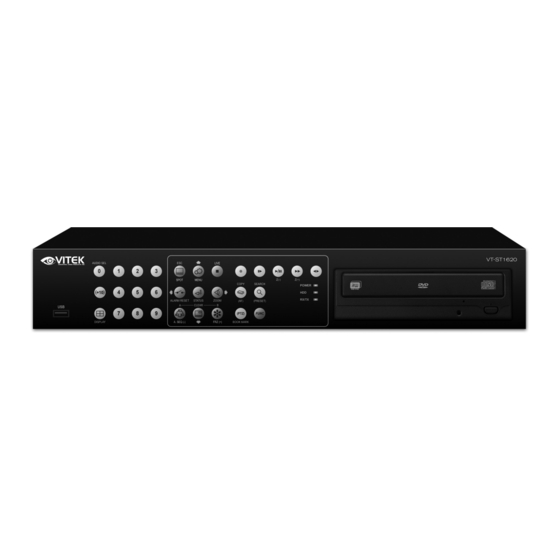
Page 18: Saga "St" Series Digital Video Recorder Layout
SAGA “ST” Series II. SAGA “ST” SERIES DIGITAL VIDEO RECORDER LAYOUT 2.1 FRONT PANEL LAYOUT 1. AUDIO SELECT This button selects the recorded audio channel when in multiple display mode. Press the button repeatedly to toggle between audio channels 1 through 4. 2. - Page 19 SAGA “ST” Series 8. PLAY / PAUSE / ZOOM OUT a) Starts the playback of recorded data. By default, the playback starts from the earliest recording. If the recording has been played back, the playback will start from where it was left off. b) Toggles between playback and pause mode.
- Page 20 SAGA “ST” Series 16. PIP / LOOP PLAYBACK CLEAR / DOWN DIRECTIONAL BUTTON a) Activates the picture-in-picture mode. b) Tilts down in PTZ mode. c) Navigates left in the menu screen. d) Moves the zoom box left in zoom mode. e) Clears the loop playback in playback mode.
-
Page 21: Rear Panel Layout
SAGA “ST” Series 2.2 REAR PANEL LAYOUT VT-ST420 11 12 13 VT-ST820 11 12 13 VT-ST1620 11 12 13... - Page 22 SAGA “ST” Series 1. CAMERA INPUT BNC connectors for composite video signal input. 2. SPOT OUTPUT Spot monitor BNC connector for composite video signal output. 3. RJ-45 ETHERNET PORT 10/100Base-T RJ-45 port for network connection. 4. RS-232C Reserved. The RS-232C port can be used to connect a variety of devices to control the DVR.
- Page 23 SAGA “ST” Series 15. RELAY OUT Terminal blocks for relay out 1 through 4. 16. TIME SYNCHRONIZATION Input and Output terminal blocks for time synchronization between DVRs. 17. ALARM INPUT Alarm input 1 through 4 on VT-ST420, 1 through 8 on VT-ST820 and 1 through 16 on VT-ST1620.
-
Page 24: Ir Remote Controller
SAGA “ST” Series 2.3 IR REMOTE CONTROLLER 1. REMOTE CONTROLLER ID Select the remote controller ID. 2. IRIS CONTROL 3. ZOOM CONTROL 4. SPOT MONITOR / ESC 5. ENTER / STATUS / HOME... - Page 25 SAGA “ST” Series 6. ALARM RESET / LEFT DIRECTIONAL BUTTON 7. MENU / UP DIRECTIONAL BUTTON 8. PIP / DOWN DIRECTIONAL BUTTON 9. DIGITAL ZOOM / RIGHT DIRECTIONAL BUTTON 10. AUTOMATIC SEQUENCE / FOCUS OUT / DECREASE VALUE 11. FREEZE / FOCUS IN / INCREASE VALUE 12.
-
Page 26: Mouse Control
SAGA “ST” Series 2.4 MOUSE CONTROL 1. LEFT MOUSE BUTTON a) Double-click in the main window: status display. b) Double-click in the menu screen: select item or icon. 2. SCROLL WHEEL Scroll up or down to change the value of the selected item. 3. -
Page 27: Installation And Connections
SAGA “ST” Series III. INSTALLATION AND CONNECTIONS 3.1 CONNECTIONS LAYOUT... -
Page 28: Vt-Xhd10U
SAGA “ST” Series 3.2 VT-XHD10U... -
Page 29: External Terminal Connection
SAGA “ST” Series 3.3 EXTERNAL TERMINAL CONNECTION 3.3.1 TIME ADJUST DESCRIPTION FALLING EDGE TIME REFERENCE INPUT TIME REFERENCE OUTPUT To Other Time Adjust Terminals 3.3.2 RELAY OUTPUT DESCRIPTION DESCRIPTION NO(Normal Open) NO(Normal Open) CM(Common) CM(Common) ALARM NC(Normal Close) NC(Normal Close) POWER NO(Normal Open) NO(Normal Open) -
Page 30: Alarm Sensor Input
SAGA “ST” Series 3.3.3 ALARM SENSOR INPUT DESCRIPTION EXTERNAL ALARM 1 INPUT EXTERNAL ALARM 2 INPUT EXTERNAL ALARM 3 INPUT EXTERNAL ALARM 4 INPUT ALARM IN COMMON GND EXTERNAL ALARM 5 INPUT EXTERNAL ALARM 6 INPUT EXTERNAL ALARM 7 INPUT EXTERNAL ALARM 8 INPUT ALARM IN COMMON GND EXTERNAL ALARM 9 INPUT... -
Page 31: Vga Pin Layout
SAGA “ST” Series 3.3.4 VGA PIN LAYOUT DESCRIPTION RED(Red Video [75ohm, 0.7Vp-p] ) GREEN(Green Video [75ohm, 0.7Vp-p] ) BLUE(Blue Video [75ohm, 0.7Vp-p] ) 4~12 Reserved HSYNC or CSYNC(Horizontal or Composite Sync.) VSYNC(Vertical Sync.) Reserved 3.3.5 RS-232C PIN LAYOUT Description Description Data Carrier Detect Data Set Ready Receive data... -
Page 32: Basic Operation
SAGA “ST” Series IV. BASIC OPERATION This section will cover basic features of the DVR, including its main screen and the explanation of some of the alerts. It will also cover the DVR status, the view modes of the DVR, automatic sequence, digital zoom, basic playback modes and audio playback. 4.1 MAIN SCREEN 1. -
Page 33: Status Screen
SAGA “ST” Series 3. DATE AND TIME Current date and time is displayed when in live monitoring mode. Recorded date and time is displayed when in playback mode. 4. CHANNEL INFORMATION The channel information is displayed. When the channel is in normal recording mode, it will display the channel title as entered by the user. - Page 34 SAGA “ST” Series 5. RECORD PROGRAM Displays current recording program. 6. RECORD TYPE Displays current event recording mode. 7. SOFTWARE VERSION Displays current software version of the DVR. 8. HARDWARE VERSION Displays current hardware version of the DVR. 9. DHCP (DYNAMIC HOST CONFIGURATION PROTOCOL) Displays the status of the DHCP application.
-
Page 35: Live View
SAGA “ST” Series 4.3 LIVE VIEW The live view displays each channel at 30 frames per second, for the total of 120 frames per second for VT-ST420, 240 frames per second for VT-ST820 and 480 frames per second for VT-ST1620. 4.3.1 LIVE VIEW MODE SEQUENCE Press the DISPLAY button to toggle between different view modes. -
Page 36: Vt-St820
SAGA “ST” Series 4.3.1.2 VT-ST820 8 Channel Mode A 7 Channel Mode 6 Channel Mode 4 Channel Mode A 4 Channel Mode B 4 Channel Mode C 4 Channel Mode D 4 Channel Mode E 4.3.2 FULL SCREEN DISPLAY Press the desired channel button to directly display the channel on the monitor. Press +10 then a secondary number for any channel numbers higher than 9. -
Page 37: Automatic Sequence
SAGA “ST” Series Press +10 button and then 2 button to directly display channel 12. 4.3.3 AUTOMATIC SEQUENCE Press the SEQ button to activate the automatic sequence display. Please change “ADD AUTO SINGLE” option to ON to include single channel display into the automatic sequence. -
Page 38: Single Screen View Mode
SAGA “ST” Series 4.4.1 SINGLE SCREEN VIEW MODE In single screen view mode, press the FREEZE button to freeze the live screen. As the screen freezes, “FREEZE” will be displayed in the upper left corner of the screen. Press the FREEZE button once more to unfreeze the screen. -
Page 39: Zoom
SAGA “ST” Series 4.5 ZOOM During the live view mode or during the playback mode, it is possible to zoom into a section of the screen to get a digital close-up of up to 8 times the normal size. Press the numeric button to select the channel to zoom into. -
Page 40: Picture-In-Picture
SAGA “ST” Series 4.6 PICTURE-IN-PICTURE Select the background channel by pressing the desired numeric button. Press the PIP button to activate the PIP mode. Pressing the numeric buttons will change the PIP window to change the channel to the desired channel. Use the directional buttons to place the PIP window to the desired location on the screen. -
Page 41: Spot Monitor
SAGA “ST” Series 4.7 SPOT MONITOR The spot monitor allows viewing of individual cameras in live mode while the main monitor may be busy with different tasks, such as playback. The ST series offers a single channel spot output. During any view modes, press the SPOT button for Spot Monitor Mode. -
Page 42: Basic Recording
SAGA “ST” Series 4.8 BASIC RECORDING The SAGA series DVR comes with 10 standard preset recording programs from the factory. By default, maximum number of pictures per second at half D1 resolution is used when the REC button is pressed whether using the recording parameters from QUICK SETUP or RECORD SETUP. -
Page 43: Basic Playback
SAGA “ST” Series 4.9 BASIC PLAYBACK 4.9.1 PLAY / REVERSE PLAY / PAUSE / STOP Press the PLAY / PAUSE button and the play icon will be displayed. The DVR starts the playback from the earliest recorded data if the playback mode is entered for the first time. -
Page 44: Fast Forward / Rewind
SAGA “ST” Series 4.9.2 FAST FORWARD / REWIND The FAST button accelerates the speed of playback in one direction. Each pressing of the button accelerates the speed twice the previous speed. In other words, from normal speed, the acceleration increment is 2X, 4X, 8X, 16X, 32X, 64X and 128X. Pressing the DIRECTION button will change the direction of fast forward to rewind while maintaining the same speed. -
Page 45: Slow
SAGA “ST” Series 4.9.4 SLOW The SLOW button slows down the speed of playback in one direction. Each pressing of the button further slows down the speed twice the previous speed. In other words, from normal speed, the slow down increment is 1/2X, 1/4X, 1/8X, 1/16X, 1/32X, 1/64X and 1/128X. -
Page 46: Bookmark
SAGA “ST” Series As soon as the end of the loop is marked, then the playback returns to POSITION A. When the end the loop is reached, the playback returns to POSITION A and the loop playback is repeated. Press the CLEAR button to exit from the loop playback mode. -
Page 47: Audio Playback
SAGA “ST” Series 4.9.7 AUDIO PLAYBACK The audio is always recorded in real time regardless of the recording speed. To listen into the desired audio channel, press the AUDIO SEL button and then channel 1 through 4. By default, the audio will playback along with the equivalent video camera (i.e. channel 1 audio will play back along with channel 1 video). -
Page 48: Advanced Operation
SAGA “ST” Series V. ADVANCED OPERATION This section will cover advanced features of the DVR such as backup (copy), pan tilt and zoom camera controls, alarm, video loss and motion recording, and various playback search options. 5.1 BACKUP The DVR is capable of backing up to various media, such as DVD-RW, CD-RW, USB Flash drives, and external hard drives. - Page 49 SAGA “ST” Series Highlight MEDIA FORMAT, and then press the ENTER button to begin formatting. FORMATTING will be displayed during the process. The process may take up to approximately 20 minutes depending on the format of the backup disk. When the process is completed, SUCCESS will be displayed.
- Page 50 SAGA “ST” Series Select the location of the file to be backed up from. If the location is unknown, leave the HDD ID on NORMAL. The beginning and the end of the available files are listed automatically as shown on the left. Select the beginning time and the end time of the period to be backed up, and then press the ENTER button to start the backup.
-
Page 51: Cd-R
SAGA “ST” Series Insert the CD into the CD-ROM or DVD-ROM of a computer, and the small player will load automatically showing all available data for playback. 5.1.2 CD-R Press the COPY button to enter the COPY screen. Highlight COPY and then press the ENTER button to access the copy submenu. - Page 52 SAGA “ST” Series The beginning and the end of the available files are listed automatically as shown on the left. Select the beginning time and the end time of the period to be backed up, and then press the ENTER button to start the backup.
-
Page 53: Usb Flash Memory
MEMOREX TravelDrive – all capacities I/O MAGIC Giga Bank – all capacities As the compatibility is continuously being tested, please check with the Vitek Help Desk before using non-listed manufacturers’ models. Insert the flash memory into any available USB 2.0 port. The flash memory will light up as it draws power from the DVR. - Page 54 SAGA “ST” Series Select the location of the file to be backed up from. If the location is unknown, leave the HDD ID on NORMAL. The beginning and the end of the available file are listed automatically as shown on the left. Select the beginning time and the end time of the period to be backed up, and then press the ENTER button to start the backup.
-
Page 55: External Hard Disk Drive
SAGA “ST” Series The copied files are listed as “Dvr-20060503- 202016.dvr”. They can be retrieved and played back using the client software, or the embedded program – “FileViewer.exe”. 5.1.4 EXTERNAL HARD DISK DRIVE Follow the same procedure as the USB flash memory in section 5.1.2. 5.1.5 COPY STATUS During any backup process, a detailed description of the copy process can be viewed. -
Page 56: Copy Stop
SAGA “ST” Series 5.1.6 COPY STOP The backup process can be interrupted at any time during the process. Press the COPY button to enter the COPY submenu. Highlight COPY and then press the ENTER button to access the copy submenu. Instead of the normal copy submenu, the DVR will display an option to stop the backup process. -
Page 57: Pan / Tilt / Zoom Camera Control
SAGA “ST” Series 5.2 PAN / TILT / ZOOM CAMERA CONTROL The SAGA series DVR comes with an extensive list of compatible PTZ cameras. Please read and follow the PTZ manufacturer’s instruction manual and understand its settings fully prior to proceeding to attempt to connect and control the PTZ camera through the DVR. -
Page 58: Advanced Recording
SAGA “ST” Series If there are no preset points predefined, then press the PRESET button once again to activate PTZ(PRESET)SET mode. Move the PTZ camera to the desired location, then press the numeric buttons to define the numbers to the locations. A total of 16 preset points can be defined. -
Page 59: Video Loss Recording
SAGA “ST” Series Verify that the alarm option has been selected in either QUICK SETUP or RECORD PROGRAM. The channels on which the alarm is triggered will display the “ALARM” message. The REC button will light up as the DVR starts to record and the channel status will change to red. -
Page 60: Advanced Playback
SAGA “ST” Series The channels which detect motion will display the “MOTION” message. The REC button will light up and the channel status will change the color to red in the channels in which the motion was detected. The recording will include the pre and post recording time on the channels that are recording. -
Page 61: Search & Copy
SAGA “ST” Series Select the desired date and then press the ENTER button. To change the month or the year, highlight the month or the year and then adjust the value by pressing the + and – buttons. When a date is selected, the DVR will then search again for the recorded data in a 24-hour period for the date. - Page 62 SAGA “ST” Series Press the SEARCH button to access the search screen. Highlight SEARCH & COPY and then press the ENTER button to access the SEARCH & COPY screen. Select which hard disk drive to retrieve the data from. If unknown, leave the HDD ID to “NORMAL”. Select the year, month, date, hour, minutes and seconds of the beginning of the data to retrieve.
- Page 63 SAGA “ST” Series Press the ENTER button and the playback will begin. Maneuver through the playback as needed. Please see BASIC PLAYBACK on page 42. When the desired footage has been found, press ESC to return to SEARCH & COPY screen. The SEARCH END TIME reflects where the DVR stopped the playback and COPY MEDIA has been highlighted automatically for the backup medium selection.
-
Page 64: Time Search
SAGA “ST” Series The backup process will begin and the progress will be displayed in the upper right hand corner of the screen. 5.4.3 TIME SEARCH Time search provides an overview of the recorded data from the earliest available recording to the latest available recording. Press the SEARCH button to access the search screen. -
Page 65: Event Search
SAGA “ST” Series Select the year, month, date, hour, minutes and seconds of the beginning of the data to retrieve. As the values change, the picture in the preview window will change accordingly. If any of the channels need to be viewed in full screen mode, highlight CHANNEL and then press the + or –... - Page 66 SAGA “ST” Series Highlight EVENT SEARCH and then press the ENTER button to access the EVENT SEARCH screen. Select which hard disk drive to retrieve the data from. If unknown, leave the HDD ID on “NORMAL”. if any of the channels need to be viewed in full screen mode, highlight CHANNEL and then press the + or –...
-
Page 67: Block Search
SAGA “ST” Series Press the ENTER button and the list of events will appear in chronological order, from the most recent to the oldest. Select the event and then press the ENTER button to start the playback. The example to the left is playing back motion triggered recording. - Page 68 SAGA “ST” Series Select the hard disk drive to retrieve the data from. If unknown, leave the HDD ID on NORMAL. Select the year, month, date, hour, minutes and seconds of the end of the data to be retrieved. Press the ENTER button and the list of data will appear in chronological order, from the most recent to the oldest.
-
Page 69: File Search
SAGA “ST” Series 5.4.6 FILE SEARCH File search is capable of reading and playing back the data from the media used for backup. Insert the CD-RW or the DVD-RW into the DVD tray or connect the USB flash memory or the external hard disk drive into the USB port. Press the SEARCH button to access the search screen. -
Page 70: Bookmark Search
SAGA “ST” Series Select the data and then press the ENTER button to start the playback. Maneuver through the playback as needed. Please see BASIC PLAYBACK on page 42. 5.4.7 BOOKMARK SEARCH Bookmark search looks up any bookmarks that have been added by the user. Please see 4.8.6 BOOKMARK under 4.8 BASIC PLAYBACK on page 45. -
Page 71: Text Search
SAGA “ST” Series Select the bookmark, and then press the ENTER button to start the playback. Maneuver through the playback as needed. Please see BASIC PLAYBACK on page 42. 5.4.8 TEXT SEARCH Text search allows searching for Point Of Sales interface entries to bring up the specific time related to a transaction. - Page 72 SAGA “ST” Series Select the hard disk drive to retrieve the data from. If unknown, leave the HDD ID on NORMAL. Select the channel in which to search for the text string. Select the year, month, date, hour, minutes and seconds of the end of the search time.
-
Page 73: Log File Search
SAGA “ST” Series Move the highlight to any location besides TEXT, and then press the enter button to list the results. Highlight an entry, and then press the ENTER button to start playback. Maneuver through the playback as needed. Please see BASIC PLAYBACK on page 42. - Page 74 SAGA “ST” Series Press the SEARCH button to access the search screen. Highlight LOG FILE SEARCH and then press the ENTER button to access the LOG FILE list. Select the year, month, date, hour, minutes and seconds of the end of the log list to retrieve. Press the ENTER button and the log list will be listed in chronological order, from the most recent to the oldest.
- Page 75 SAGA “ST” Series The log file will be saved as “DvrLog.log” file. Double-click the left mouse button to open and view the log file.
-
Page 76: Dvr Menu
SAGA “ST” Series VI. DVR MENU Press the MENU button to access the main menu of the DVR. The DVR menu consists of the following categories: EXIT COPY SEARCH LINK SETUP SYSTEM SETUP EVENT SETUP RECORD SETUP SCREEN SETUP QUICK SETUP... -
Page 77: Quick Setup
SAGA “ST” Series 6.1 QUICK SETUP Quick setup enables the user to quickly setup major recording settings of the DVR. All changes made in quick setup are affected equally to all channels. This includes the image size, record speed, image quality, event options, pre and post recording time and audio record settings. -
Page 78: Record Frame
SAGA “ST” Series 6.1.3 RECORD FRAME Record frame determines the overall recording speed of the DVR. The recording speed adjusts automatically according to the image size and divided equally between all available channels. As an example, the 60 available recording speed is divided equally between 16 channels on the VT-ST1620. -
Page 79: Post-Record Time
SAGA “ST” Series 6.1.6 POST-RECORD TIME Define the post-event recording time. Select from 0 to 60 seconds. The default is ten seconds. 6.1.7 IMAGE QUALITY Define the recording image quality. Available options are LOW, FINE and SUPERFINE. The default is FINE. -
Page 80: Screen Setup
SAGA “ST” Series 6.2 SCREEN SETUP Screen setup defines various screen related options. Any changes affect the main video as well as the spot monitor output of the DVR. 6.2.1 AUTO SEQUENCE Highlight AUTO SEQUENCE and then press the ENTER button to access four pages of the auto sequence submenu. - Page 81 SAGA “ST” Series The second page lists the sequence display duration for the nine channel display mode A and B, ten channel display mode, 13 channel display mode, 16 channel display mode, and the option to include single channels. Select the inclusion of single channels in the automatic sequence.
-
Page 82: Display
SAGA “ST” Series 6.2.2 DISPLAY Highlight DISPLAY and then press the ENTER button to access the display submenu. Select the display option for the remaining space on the hard disk drive. The default is on. Select the display mode for the remaining free space on the hard disk drive. - Page 83 SAGA “ST” Series Select the date format. The default is DD/MM/YY. Select the display option for the channel title. The default is on. Select the display mode for the channel title. The default is in text mode. The bitmap mode title can only be edited using the client software.
-
Page 84: Title
SAGA “ST” Series 6.2.3 TITLE Highlight TITLE and then press the ENTER button to access the title submenu. Press the enter button to edit the channel title. Navigate through the characters by using the directional buttons, and advance through the characters using the + or –... -
Page 85: Covert
SAGA “ST” Series Select a view mode to customize. The view mode can be disabled to be removed from the sequence of view modes. The default is on. Highlight the channel to customize, and then press the + or – button to select the desired channel. 6.2.5 COVERT Highlight COVERT and then press the ENTER button to access the covert channel submenu. -
Page 86: Spot
SAGA “ST” Series The second page lists the covert mode options for channels 9 through 16. Highlight the desired channel and press the + or – button to activate the covert mode. Select the covert mode application. By default, the live view, playback and network are affected by the covert mode. - Page 87 SAGA “ST” Series Select the spot monitor display mode: Manual Event Sequenced The default is manual. Define the spot monitor sequence mode time from 1 to 60 seconds. The default is 3 seconds. The channels without video signals can be skipped. Select on or off.
-
Page 88: Record
SAGA “ST” Series 6.3 RECORD Record setup defines various recording options such as record schedule, record programs, recording time estimate, audio recording, repeat recording, play modes, backup mode and holiday recording schedules. 6.3.1 RECORD SETUP There are 10 customizable Record Programs arranged in hourly blocks that can be individually scheduled and adjusted. - Page 89 SAGA “ST” Series 1. All Select the program for the whole day by changing the value in this section. 2. Current hour block Highlights the current program for the current time. 3. Schedule recording Displays the hour blocks with schedule recording. Schedule recording forces the DVR to record even when the REC button is off.
-
Page 90: Record Program
SAGA “ST” Series Any of the record settings can be customized once in the record program mode. Any changes made will be effective only to the hour block. 6.3.2 RECORD PROGRAM Highlight RECORD PROGRAM and then press the ENTER button to access the record program submenu. - Page 91 SAGA “ST” Series 2. EVENT RECORD SETTING The DVR has two ways of responding to an event: SINGLE mode and COMPLEX mode. Each mode has two options to further define the event recording modes, EVENT CHANNEL ONLY and ALL CHANNELS, for a total of four distinct ways to respond to an event.
-
Page 92: Image Quality
SAGA “ST” Series B. COMPLEX MODE 1) Event Channel Only The event channel records at a predetermined recording speed. . 2) All Channels The event channel and the rest of the channels record at a predetermined recording speed. 3) RECORD QUALITY Select the record quality for normal recording and event recording. -
Page 93: Audio Record
SAGA “ST” Series 6.3.4 AUDIO RECORD Highlight AUDIO RECORD and then press the ENTER button to access the audio record submenu. Enable or disable the audio recording option for channels 1 through 4. The default is off. 6.3.5 REPEAT RECORD Highlight REPEAT RECORD and then press the ENTER button to access the audio record submenu. -
Page 94: Play Mode
SAGA “ST” Series 6.3.6 PLAY MODE Select the playback mode for the recorded data. Available options are: FRAME: for higher frame rate FIELD: for lower frame rate As the general rule of thumb, FRAME mode is recommended for playing back recording rates of 10 pictures per second or higher, and FIELD mode is recommended for recording rates of 10 pictures per second or lower. -
Page 95: Event
SAGA “ST” Series Define the holidays in MM/DD format. Adjust the values using the + or – buttons. 6.4 EVENT Event setup defines various event options such as the motion grid and the motion detection sensitivity, the main screen event response option, buzzer option, sensor input and relay output options. - Page 96 SAGA “ST” Series Select the channel to customize motion related options by pressing the + or – buttons. Adjust the sensitivity of the motion detection from 1 to 5 by pressing the + or – buttons. The default is 5. Highlight AREA SETUP and then press the ENTER button to access the motion grid setup screen.
-
Page 97: Event Screen Mode
SAGA “ST” Series Any grid that detects motion will flash a purple tint for the period of time that it detects motion. 6.4.2 EVENT SCREEN MODE Define how the main video output reacts when an event occurs. SCREEN HOLD: maintains the current view mode. -
Page 98: Event Message Reset
SAGA “ST” Series 6.4.5 EVENT MESSAGE RESET Select the duration of the event message to be displayed from 1 to 30 seconds. The default is 5 seconds. 6.4.6 EVENT BUZZER Select the buzzer option on or off. The default is off. 6.4.7 SENSOR INPUT Highlight SENSOR INPUT and then press the ENTER button to access the sensor input submenu. -
Page 99: Relay Output
SAGA “ST” Series 6.4.8 RELAY OUTPUT Highlight RELAY OUTPUT and then press the ENTER button to access the relay output submenu. The first page lists relay output options for channels 1 through 8. For each channel, it is possible to customize relay 1 through 3 for each of the event options. -
Page 100: System
SAGA “ST” Series 6.5 SYSTEM System setup defines various system settings such as hard disk drive settings, system clock, password for multiple users, video standard, language, remote controller, and the key echo. Moreover the system settings can be reinitialized, saved or retrieved from the USB flash memory, as well as updating the DVR firmware. -
Page 101: Rec Hdd Initialize
SAGA “ST” Series The DVR detects installed hard disk drives automatically. Any hard disk drive can be defined to be a normal recording drive (REC drive) or a backup drive (BACKUP). Highlight a desired drive and then select the function for the hard disk drive by pressing the + or –... -
Page 102: Backup Hdd Initialize
SAGA “ST” Series 6.5.1.3 Backup HDD initialize The backup hard disk drives can be initialized at any time by accessing this menu. Highlight BACKUP HDD INITIALIZE and then press the ENTER button to access the initialization screen. Select YES and then press the ENTER button to initialize the hard disk drives. -
Page 103: Time Adjust
SAGA “ST” Series Advance through the year, month, date and time by using the directional buttons, and use the + or – button to adjust the values. Once the value has been adjusted, press the ENTER button to make the new date and time effective. -
Page 104: Password
SAGA “ST” Series Select the time zone for the local time. For the list of the time zone for your local area, please see Appendix I on page 172. Select the DAYLIGHT SAVINGS TIME option on or off. The default is off. Define the daylight savings time starting month, week, day and time. -
Page 105: Password Check
SAGA “ST” Series 6.5.3.1 Password Check Select password check option on or off. When enabled, it will prompt for password on the following functions unless disabled individually under user settings: REC button Search & Play buttons Copy button Live Audio selection Main Menu button Status button PTZ control button... -
Page 106: User Authority
SAGA “ST” Series 6.5.3.3 User Authority Highlight USER AUTHORITY and then press the ENTER button to access user authority screen. Highlight and modify each user’s level of authority by pressing the + or – buttons. 6.5.4 VIDEO STANDARD Select the video standard by pressing the + or – buttons. -
Page 107: Remote Control Id
SAGA “ST” Series 6.5.6 REMOTE CONTROL ID If there is more than one DVR present at the same location and each DVR needs to be controlled separately using a remote controller, then each DVR can be addressed differently so that all of them can be controlled using one remote controller. Highlight REMOTE CONTROL ID and then press the + or –... -
Page 108: Menu Initialize
SAGA “ST” Series 6.5.8.1 Menu initialize Highlight MENU INITIALIZE and then press the ENTER button to reset all menu settings back to factory default. Select YES and then press the ENTER button to reset back to factory default. Select NO to exit without resetting. -
Page 109: Save Menu To File
SAGA “ST” Series 6.5.8.3 Save menu to file Highlight SAVE MENU TO FILE and then press the ENTER button to save the menu settings onto a USB flash memory. The USB flash memory must be inserted into the front USB port. When saving the DVR menu settings is successful, the DVR will display “ENV COPY SUCCESS”. -
Page 110: Do Not Remove The Usb Flash Memory From The Usb Port During The Upgrade
SAGA “ST” Series The DVR will start reading the available upgrade file. Once the file is found, it will check for the integrity of the file. If the integrity of the file is intact, then it will start the upgrade process. The upgrade progress will be shown in percentages. -
Page 111: Link
SAGA “ST” Series 6.6 LINK Link setup defines various settings between the DVR and various devices such as internet connection, keyboard controllers, PTZ cameras and e-mails. 6.6.1 NETWORK Highlight NETWORK and then press the ENTER button to access the network setup submenu. Select DHCP option on or off. - Page 112 SAGA “ST” Series Define the IP address if the DHCP is set to off. The DVR should be provided with its own static IP address. Define the subnet mask. The subnet mask should also be provided along with the IP address. Define the gateway.
-
Page 113: Rs-232C
DVR. Vitek provides a dynamic IP server to find the DVR even if it is connected on a dynamic IP service. Define the secondary dynamic IP server’s address if a proprietary server is to be setup and used in conjunction with the DVR. -
Page 114: 113
SAGA “ST” Series Select the data bit. Available options are 6 to 8. The default bit is 8. Select the parity bit. Available options are ODD, EVEN and NONE. The default is NONE. Select the stop bit. Available options are 1 and 2. The default is 1. - Page 115 SAGA “ST” Series Select the communication speed. Available speeds are from 1200 to 115200. The default speed is 115200. Select the data bit. Available options are 6 to 8. The default bit is 8. Select the parity bit. Available options are ODD, EVEN and NONE.
-
Page 116: Ptz
Panasonic WV-CS854A Daiwa DMP23 LG Electronics LPT-A100L Bosch TC8560/TC700 Vitek EZ (Xpress Dome) TK-C655/C676 Sunkwang SK-D106 Highlight PTZ and then press the ENTER button to access PTZ camera submenu. Highlight the desired channel number where the PTZ camera is connected, then scroll through the list of... -
Page 117: E-Mail
SAGA “ST” Series Select the communication speed. Available speeds are from 1200 to 115200. The default is 9600. Select and match the PTZ camera address. For example, if the PTZ camera is set to address 2, then the ID should be set to 2. 6.6.5 E-MAIL The DVR is capable of sending e-mails when an event occurs to up to ten different e- mail addresses. -
Page 118: Smtp Server
SAGA “ST” Series 6.6.5.2 SMTP server Highlight SMTP SERVER and then press the ENTER button to define an e-mail server. Enter the e-mail server’s address. For example: mail.domainname.com Press the ESC button to return to previous menu. 6.6.5.3 DVR e-mail address Highlight DVR E-MAIL ADDRESS and then press the ENTER button to define the DVR’s e-mail address. -
Page 119: User Id
SAGA “ST” Series 6.6.5.4 User ID Highlight USER ID and then press the ENTER button to define the user ID for the DVR’s e-mail account. Enter the user name to log into the DVR’s e-mail account. Press the ESC button to return to previous menu. 6.6.5.5 Password Highlight PASSWORD and then press the ENTER button to define the password for the DVR’s e-mail... -
Page 120: E-Mail Address 1 Through 10
SAGA “ST” Series 6.6.5.6 E-mail address 1 through 10 Highlight a desired e-mail address to send the notifications to, and then press the ENTER button to define the e-mail address. Enter the e-mail address. Press the ESC button to return to the previous menu. -
Page 121: Search
SAGA “ST” Series VII. SEARCH 5.4 ADVANCED PLAYBACK V. ADVANCED Please see under section OPERATION on page 59. VIII. COPY 5.1 BACKUP V. ADVANCED OPERATION Please see under section on page... -
Page 122: Exit
SAGA “ST” Series IX. EXIT Any and all settings must be saved in order to be put into effect. After any setting has been modified, the ESC button can be pressed several times until the EXIT screen is shown. 9.1 SAVE ONLY SAVE ONLY will be automatically highlighted when the ESC button is pressed. -
Page 123: Exit Without Save
SAGA “ST” Series 9.3 EXIT WITHOUT SAVE Highlight and press the ENTER button to disregard any changes and exit to the live screen view mode. -
Page 124: Client Program
SAGA “ST” Series X. CLIENT PROGRAM: DVR VIEWER The DVR Viewer is a dedicated client program that connects to, monitors and manages up to 16 DVRs simultaneously. 10.1 SYSTEM REQUIREMENT The DVR Viewer receives, decodes and displays data for up to 16 DVRs or up to 256 cameras simultaneously requiring a powerful personal computer to take full advantage of the program. - Page 125 SAGA “ST” Series Click on NEXT. The DVR viewer will be installed in its default folder of C:\Program Files\DVR\DVR-Viewer. If the folder needs to be changed, click on “BROWSE…” button and then select a different folder. The setup program will run through its series of installation process.
-
Page 126: Dvr Viewer - Layout
SAGA “ST” Series 10.3 DVR VIEWER - LAYOUT Locate the DvrViewer icon on the desktop and double-click on it to run the client software. The program can also be located in START- Programs – DVR-Viewer. When the DVR Viewer is run for the first time, it prompts for the administrator’s password. - Page 127 SAGA “ST” Series 1. DVR LIST The DVR List adds or removes individual DVRs and offers a variety of connection options. DVR List The DVRs that have been added are listed in this box. Connection Type Select the connection type to the DVR. DVR Name Enter the DVR name.
- Page 128 SAGA “ST” Series Use IP Server The DVR can be located on the internet using the MAC address displayed in the status screen. If the MAC address is to be used, “Use IP Server” box must be checked. f. Domain Name / Use DDNS The DVR can be located on the internet using a domain name, or a web address.
- Page 129 SAGA “ST” Series 2. DVR SEARCH Within a local area network environment (LAN), it is possible to automatically scan and list available DVRs to be added to the DVR list. Click on DVR SEARCH to open the DVR Search window. Click on SEARCH, and available DVRs will be listed.
- Page 130 SAGA “ST” Series 3. HDD SEARCH The hard disk drive from the DVR can be directly connected to a PC, where the files can be searched and played back through the DVR Viewer. Click on HDD SEARCH to open the HDD Search window Select a hard disk drive, and then click on Recorded channels will be shown in the...
- Page 131 SAGA “ST” Series If the desired file is not listed in the current folder, then select the folder in which the files are saved by clicking on FOLDER SELECT. Select a file to view, and then click on PLAY to begin the playback.
- Page 132 SAGA “ST” Series 5 ~ 9 DVRS 10 ~ 16 DVRS 6. VIEWER OPTION Viewer option defines the administrative options for the DVR Viewer, such as display options and the IP address of the Dynamic IP Server, and user management to create user name and passwords for additional users to access the DVR Viewer.
- Page 133 SAGA “ST” Series 6.2 User Management Click on USER MANAGEMENT to access the User Management window. Modify the administrator’s description and passwords as needed. Up to 20 alphanumeric characters can be entered for the password. Press CHANGE to save the modification. To add additional users, click on ADD.
- Page 134 SAGA “ST” Series The user setting can be modified by highlighting the user and clicking on CHANGE once the changes are made. 7. CHANNEL DISPLAY WINDOW Live or playback video from the DVR is transmitted and displayed up to 16 channels. Each channel displays information regarding the specific channel according to the settings in VIEWER OPTION.
- Page 135 SAGA “ST” Series 15. DVR CONTROLLER Just as the IR remote controller, mouse and the front buttons on the DVR, the client software provides a controller to control the DVR remotely. The button functions are identical to the front buttons of the SAGA “ST” series DVR. For more information on button functions, please see 2.1 FRONT PANEL LAYOUT under II.
- Page 136 SAGA “ST” Series D. Move to preset points Click on any of the 16 buttons to move the PTZ camera to predefined preset position. E. Zoom control Zoom in and out by clicking on the – or + buttons. F. PTZ movement speed Select the movement speed ratio.
- Page 137 SAGA “ST” Series 18.2 Record Record status displays the following information: Record program Event record mode Record repeat Number of record hard disk drives Logical Block Address of the record hard disk drives Number of backup hard disk drives Logical Bock Address of the backup hard disk drives Record status 18.3 Network...
- Page 138 SAGA “ST” Series a. Zoom in / out Click the + or – button to zoom in and out for the detailed view of the picture. b. Paper size Select the paper size. Available paper sizes are A3, A4, A5, B4, B5, Legal and Letter.
- Page 139 SAGA “ST” Series a. Available data Displays available data to be downloaded. b. Hard disk drive selection Select the hard disk drive to download from. If unknown, leave the selection on NORMAL. c. Copy time Define the interval of the file to be downloaded. Available time interval is 1 through 60 minutes.
- Page 140 SAGA “ST” Series 23. TIME SEARCH Search for a specific time for remote playback using a time line. Please see 10.5.1 TIME SEARCH under 10.5 DVR VIEWER – PLAYBACK MODE on page 145. 24. CALENDAR SEARCH Search for a time for remote playback using a calendar based search window. Please see 10.5.2 CALENDAR SEARCH under 10.5 DVR VIEWER –...
- Page 141 SAGA “ST” Series c. Search time Select the year, month, date, hour, minutes and seconds of the end of the log list to retrieve. d. Save log Save the log list onto the computer. e. Cancel Exit from the log search window. 29.
- Page 142 SAGA “ST” Series h. Fast forward This button can be toggled for fast forward speed of 2x, 4x, 8x, 16x, 32x, 64x and 128x. 30. CHANNEL STATUS Displays the status of the channels. Grey: non-recording mode Yellow: manual recording mode Red: event recording mode Green: schedule recording / playback mode 31.
-
Page 143: Dvr Viewer - Live Mode
SAGA “ST” Series 10.4 DVR VIEWER - LIVE MODE Click on the DVR LIST, highlight a desired DVR and then click on CONNECT. a. DVR’s local time Displays the DVR’s local date and time b. Event message Displays the channel’s event messages, alarm and motion. - Page 144 SAGA “ST” Series c. Channel window The DVR channel window can be double-clicked for a full screen mode. The channel window can also be zoomed by dragging the left mouse button over the channel window. The size of the box created by dragging will be the outline of the channel window to be zoomed in.
-
Page 145: Dvr Viewer - Playback Mode
SAGA “ST” Series 10.5 DVR VIEWER – PLAYBACK MODE Any DVRs that are connected online can be accessed to do data search remotely from the DVR and then transmit to the DVR viewer for remote playback. a. DVR’s playback time Displays the DVR’s playback date and time. -
Page 146: Time Search
SAGA “ST” Series d. DVR functions Some of the DVR functions may not be available depending on what user account the DVR Viewer has been signed on with, and also with what user level password the DVR has been connected to. e. -
Page 147: Calendar Search
SAGA “ST” Series Select the channel for playback. Select the year, month, day and time for the playback, or slide the time bar to the desired time. Click on PLAY to begin the remote playback. 10.5.2 CALENDAR SEARCH Click on CALENDAR to display the Calendar Search window. -
Page 148: Event
SAGA “ST” Series 10.5.3 EVENT Click on EVENT to display the Event Search window. The first 500 events are listed chronologically, from the most recent to the oldest. Select an event and then click on PLAY to begin remote playback. If the desired event is not listed in the current window, then follow the following steps. -
Page 149: Text
SAGA “ST” Series Select the year, month, day and time for the end of the event list for playback. The list can be advanced to the next 500 lists by clicking on NEXT. Highlight the desired event and then click on PLAY to begin the remote playback. - Page 150 SAGA “ST” Series Select the channel for the text string search. Enter the text string to search. Leave blank for a wild card (all items) search. Select the year, month, day and time for the end of the search time. Click on SEARCH to list data that match the text string.
-
Page 151: Block
SAGA “ST” Series Highlight a text string, and then click on PLAY to begin the remote playback. The listing can be saved as a List file format. 10.5.5 BLOCK Click on BLOCK to display the Logical Block Address Search window. The first 500 data is displayed in chronological order, from the most recent to the oldest. - Page 152 SAGA “ST” Series Select the year, month, day and time for the end of the data. If the desired date and time is not found, then click on NEXT to display the next 500 Logical Block Addresses. Highlight a desired block time and then click on PLAY to begin the remote playback.
-
Page 153: Dvr Player - Setup
SAGA “ST” Series 10.6 DVR PLAYER – SETUP The DVR Viewer can change the settings on the DVR remotely. The features and settings are identical to that of the DVR menu. For more information, please see V. DVR MENU on page 75. Click on SETUP and the password prompt will be displayed. -
Page 154: Quick Setup
SAGA “ST” Series 5. SYSTEM SETUP 6. LINK 7. DOWNLOAD Update the DVR’s firmware using the download menu. 8. READ FROM FILE Load DVR settings from a DVR setup file. 9. SAVE TO FILE Save DVR settings to a DVR setup file. 10. -
Page 155: Screen
SAGA “ST” Series 10.6.2 SCREEN 10.6.2.1 Auto Sequence a. Auto-Single: select the single channel dwell time. b. Auto-Split: select the multi channel dwell time. c. Video Loss Skip: check / uncheck. d. Add Auto Single: check / uncheck. 10.6.2.2 Display a. -
Page 156: Title
SAGA “ST” Series 10.6.2.4 Title a. Channel Title (text mode) Enter up to eight alphanumeric characters for channel titles. b. Clear Clear the bitmap drawing. c. Move Move the bitmap drawing in the grids. d. Font Select the font for bitmap conversion. e. -
Page 157: Multiscreen
SAGA “ST” Series 10.6.2.5 Multiscreen Customize the channels to be displayed in 4E, 6, 7, 9B, 10 and 13 channel view modes. 10.6.2.6 Covert a. Channels 1 through 16: on / off. b. Select: live, play, network, LV & PB, LV & NW, PB &... -
Page 158: Record
SAGA “ST” Series 10.6.3 RECORD 10.6.3.1 Record a. Schedule Record: click on a hour block and then click Schedule Record on / off. b. Monday through Sunday: select the record program. c. Repeat Record: on / off. d. Repeat Record Alarm: 5% through 10%, off. e. -
Page 159: Holiday
SAGA “ST” Series 10.6.3.3 Holiday a. Holiday Record: on / off. b. Holiday Setup: enter the holidays. 10.6.4 EVENT 10.6.4.1 Event a. Event Check: on / off. b. Event Screen Mode: screen hold, event full, event multi, event full return, event multi return. c. -
Page 160: Sensor Input
SAGA “ST” Series Select the grid size. Use the left mouse button to draw motion detection area and use the right mouse button to erase motion detection area. Use the buttons at the bottom of the screen to set or clear motion detection all area of the screen. -
Page 161: System
SAGA “ST” Series 10.6.5 SYSTEM 10.6.5.1 System a. Video Standard: PAL, NTSC, auto. b. Language: English, Korean, Japanese, Polish, Spanish, Russian and Chinese. c. Remote Control ID: All, 11 through 14, 21 through 24, 31 through 34 and 41 through 44. d. -
Page 162: Password
SAGA “ST” Series 10.6.5.3 PASSWORD a. Password Check: on / off b. Passwords: define the DVR access passwords for all users. c. Authority: define DVR access authority for users 1 through 4. 10.6.6 LINK 10.6.6.1 Network a. DHCP: on / off. b. -
Page 163: 162
SAGA “ST” Series 10.6.6.3 RS-485 a. System ID: select the system ID. b. Output Mode: select the output mode. c. Baud Rate: select the communication speed. d. Data Bit: select the data bit. e. Parity Bit: select the parity bit. Stop Bit: select the stop bit. -
Page 164: Download
SAGA “ST” Series 10.6.7 DOWNLOAD The DVR’s firmware can be updated from the client software. Please remember that once the upgrade process begins, the connection must not be severed or interrupted. Click on FIRMWARE DOWNLOAD, and the DVR firmware open window will open. Locate the upgrade file and then click on OPEN to begin the upgrade process. - Page 165 SAGA “ST” Series Once the download is complete, the DVR will begin flashing the new firmware. Once the upgrade is finished and successful, the DVR viewer will display “DVR Upgraded Successfully!!” Restart the DVR, and the new firmware will be in effect.
-
Page 166: Specifications
SAGA “ST” Series XI. SPECIFICATIONS 11.1 VT-ST420 Video Video Standard NTSC & PAL Standards, automatic configuration Video Input 4 Channels BNC Input Level 1.0 Vp-p ± 10% Composite, 75 Ohm Balanced. Loop Through Output 4 Channels BNC w/ Automatic Signal Boost Main Video Output 1.0 Vp-p Composite, 75 Ohm Balanced Spot Video Output... - Page 167 SAGA “ST” Series Storage Internal Storage 2 Hard Drives, 1 removable, 1.5 Terabytes Maximum External Storage 40 Hard Drives, 20 Terabytes Maximum Speed 5400 RPM Minimum, 7200 RPM Maximum 45Mhz DMA Hard Drive Type EIDE Compatible Seek Time Faster than 9.0ms average Expansion Bay Interface USB 2.0 Data Redundancy...
-
Page 168: Vt-St820
SAGA “ST” Series 11.2 VT-ST820 Video Video Standard NTSC & PAL Standards, automatic configuration Video Input 8 Channels BNC Input Level 1.0 Vp-p ± 10% Composite, 75 Ohm Balanced. Loop Through Output 8 Channels BNC w/ Automatic Signal Boost Main Video Output 1.0 Vp-p Composite, 75 Ohm Balanced Spot Video Output 1.0 Vp-p Composite, 75 Ohm Balanced... - Page 169 SAGA “ST” Series Storage Internal Storage 2 Hard Drives, 1 removable, 1.5 Terabytes Maximum External Storage 40 Hard Drives, 20 Terabytes Maximum Speed 5400 RPM Minimum, 7200 RPM Maximum 45Mhz DMA Hard Drive Type EIDE Compatible Seek Time Faster than 9.0ms average Expansion Bay Interface USB 2.0 Data Redundancy...
-
Page 170: Vt-St1620
SAGA “ST” Series 11.3 VT-ST1620 Video Video Standard NTSC & PAL Standards, automatic configuration Video Input 16 Channels BNC Input Level 1.0 Vp-p ± 10% Composite, 75 Ohm Balanced. Loop Through Output 16 Channels BNC w/ Automatic Signal Boost Main Video Output 1.0 Vp-p Composite, 75 Ohm Balanced Spot Video Output 1.0 Vp-p Composite, 75 Ohm Balanced... - Page 171 SAGA “ST” Series Storage Internal Storage 2 Hard Drives, 1 removable, 1.5 Terabytes Maximum External Storage 40 Hard Drives, 20 Terabytes Maximum Speed 5400 RPM Minimum, 7200 RPM Maximum 45Mhz DMA Hard Drive Type EIDE Compatible Seek Time Faster than 9.0ms average Expansion Bay Interface USB 2.0 Data Redundancy...
-
Page 172: Technical Support
XII. TECHNICAL SUPPORT Please read the manual thoroughly before contacting the vendor or the manufacturer. If you still have questions or problems operating the DVR correctly, then please contact: VITEK INDUSTRIAL VIDEO PRODUCTS, INC. 28492 Constellation Road Valencia, CA 91355 Toll Free: (888) VITEK –... -
Page 173: Time Zone Listing
SAGA “ST” Series APPENDIX I TIME ZONE LISTING GMT-12:00 International Date Line West GMT-11:00 Midway Island, Samoa GMT-10:00 Hawaii GMT-09:00 Alaska GMT-08:00 Pacific Time (US & Canada); Tijuana GMT-07:00 Arizona GMT-07:00 Chihuahua, La Paz, Mazatlan GMT-07:00 Mountain Time (US & Canada) GMT-06:00 Central America GMT-06:00... - Page 174 SAGA “ST” Series GMT+03:00 Nairobi GMT+03:30 Tehran GMT+04:00 Abu Dhabi, Muscat GMT+04:00 Baku, Tbilisi, Yeveran GMT+04:30 Kabul GMT+05:00 Ekaterinburg GMT+05:00 Islamabad, Karachi, Tashkent GMT+05:30 Chennai, Kolkata, Mumbai, New Delhi GMT+05:45 Kathmandu GMT+06:00 Almaty, Novosibirsk GMT+06:00 Astana, Dhaka GMT+06:00 Sri Jayawardenepura GMT+06:30 Rangoon GMT+07:00...
-
Page 175: Index
SAGA “ST” Series INDEX DIRECTION........17, 18, 24, 42, 43, 44 DIRECTIONAL BUTTON..........24 DISPLAY............. 18, 34, 81 DNS ..........15, 33, 111, 127, 136, 161 ADVANCED OPERATION ........47, 120 Domain Name ............111, 127 ADVANCED PLAYBACK..........59 DOMAIN NAME SERVER..........33 ADVANCED RECORDING..........57 DOWN DIRECTIONAL BUTTON ........ - Page 176 SAGA “ST” Series FIXED HDD..............32 Motion Detection ............158 FOCUS IN ..............19, 24 MOTION RECORDING..........58 FOCUS OUT.............18, 24 MOUSE................25 FRAMES PER SECOND ..........141 Multiscreen..............156 FREEZE ............19, 24, 36, 37 MULTISCREEN.............. 83 FULL SCREEN DISPLAY ..........35 FUNCTION button...............19, 24, 56 Network................
- Page 177 SAGA “ST” Series REMOTE CONTROL ID.........78, 106 SYSTEM................99 REMOVABLE HDD RACK..........19 SYSTEM REQUIREMENT........... 123 REPEAT RECORD ............92 REWIND ................43 RIGHT DIRECTIONAL BUTTON.........19 RJ-45 ETHERNET PORT ..........21 TEST MOTION .............. 95 RS-232C..........21, 112, 127, 161 TEXT ................148 RS-422................113 Time Adjust..............
-
Page 178: Notes
SAGA “ST” Series NOTES... - Page 179 SAGA “ST” Series NOTES...
- Page 180 28492 CONSTELLATION ROAD VALENCIA, CA 91355 WWW.VITEKCCTV.COM | 888-VITEK-70...
Need help?
Do you have a question about the SAGA “ST” Series and is the answer not in the manual?
Questions and answers