H3C S5500-28C-EI Installation Manual
S5500-ei series ethernet switches
Hide thumbs
Also See for S5500-28C-EI:
- Installation manual (95 pages) ,
- Quick start manual (91 pages) ,
- Quick start manual (9 pages)

Related Manuals for H3C S5500-28C-EI


Summary of Contents for H3C S5500-28C-EI
- Page 1 H3C S5500-EI Series Ethernet Switches Installation Manual Hangzhou H3C Technologies Co., Ltd. http://www.h3c.com Manual Version: 20071215-C-1.01...
- Page 2 Copyright © 2007, Hangzhou H3C Technologies Co., Ltd. and its licensors All Rights Reserved No part of this manual may be reproduced or transmitted in any form or by any means without prior written consent of Hangzhou H3C Technologies Co., Ltd. Trademarks H3C, , Aolynk,...
-
Page 3: About This Manual
About This Manual Related Documentation In addition to this manual, each H3C S5500-EI Series Ethernet Switches documentation set includes the following: Manual Description H3C S5500-EI Series Ethernet Switches It is used for assisting the users in data Operation Manual configurations and typical applications. H3C S5500-EI Series Ethernet Switches It is used for assisting the users in using Command Manual... - Page 4 Conventions The manual uses the following conventions: I. GUI conventions Convention Description Button names are inside angle brackets. For example, click < > <OK>. Window names, menu items, data table and field names are inside square brackets. For example, pop up the [New User] window.
-
Page 5: Table Of Contents
H3C S5500-EI Series Ethernet Switches Table of Contents Table of Contents Chapter 1 Product Overview ......................1-1 1.1 Introduction ........................1-1 1.2 S5500-28C-EI ........................1-2 1.2.1 Appearance ......................1-2 1.2.2 Front Panel......................1-3 1.2.3 Rear Panel ......................1-3 1.2.4 Power Supply System ..................... 1-3 1.2.5 Cooling System ....................... - Page 6 Installation Manual H3C S5500-EI Series Ethernet Switches Table of Contents 1.7.1 Appearance ......................1-21 1.7.2 Front Panel......................1-22 1.7.3 Rear Panel ......................1-22 1.7.4 Power System ....................... 1-22 1.7.5 Cooling System ..................... 1-23 1.7.6 LEDs........................1-23 1.8 System Specifications of the S5500-EI Series ..............1-26 1.9 Pluggable Modules ......................
- Page 7 Installation Manual H3C S5500-EI Series Ethernet Switches Table of Contents Chapter 4 Initial Power-On ......................4-1 4.1 Setting Up the Configuration Environment ................ 4-1 4.2 Connecting the Console Cable ..................4-1 4.3 Setting Terminal Parameters ..................... 4-1 4.4 Booting the Switch ......................4-5 4.4.1 Checking before Power-On..................
-
Page 8: Chapter 1 Product Overview
Model 1000Base-X SFP 10/100/1000Base-T console ports Ethernet ports ports S5500-28C-EI S5500-28C-EI-DC S5500-52C-EI S5500-28C-PWR-EI S5500-52C-PWR-EI S5500-28F-EI Together with an auto-sensing 10/100/1000BASE-T Ethernet port, each 1000Base-X SFP port forms a Combo port. For each Combo port, either the SFP port or the auto-sensing 10/100/1000BASE-T Ethernet port can be used at a time. -
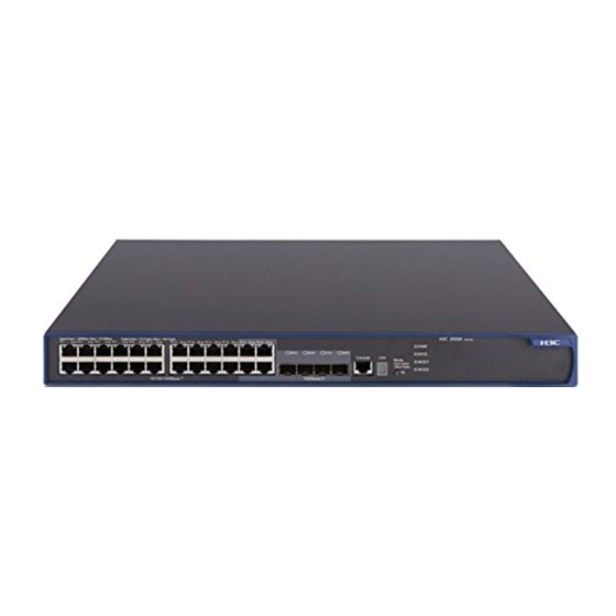
Page 9: S5500-28C-Ei
1000Base-X SFP ports, and one console port on the front panel, and one AC power socket, one redundant power system (RPS) port, and two extended module slots on the rear panel. Figure 1-2 shows the appearance of the S5500-28C-EI. Figure 1-1 Appearance of the S5500-28C-EI... -
Page 10: Front Panel
(5) Extended module slot 2 Figure 1-3 Rear panel of the S5500-28C-EI 1.2.4 Power Supply System The S5500-28C-EI can adopt AC input, or 12 V RPS input, or both to provide backup. Only the recommended RPS can be used. AC power input... -
Page 11: Cooling System
H3C S5500-EI Series Ethernet Switches Chapter 1 Product Overview 1.2.5 Cooling System The S5500-28C-EI is equipped with four fans for heat dissipation. 1.2.6 LEDs For descriptions about LEDs, see Table 1-3. You can switch the Mode LED display mode between speed and duplex by pressing the Mode button on the panel. - Page 12 Installation Manual H3C S5500-EI Series Ethernet Switches Chapter 1 Product Overview Mark Status Description The LED displays the power POST test ID. POST LED flashes running green The LED flashes the POST test ID of the power POST failed test. LED flashes failed A bar rotates clockwise...
- Page 13 Installation Manual H3C S5500-EI Series Ethernet Switches Chapter 1 Product Overview Mark Status Description A 1000 Mbps link is present. When data is Green being received or sent, the LED flashes at a high frequency. A 10/100 Mbps link is present.
-
Page 14: S5500-28C-Ei-Dc
Ethernet ports, four 1000Base-X SFP ports, and one console port on the front panel, and one –48 VDC power socket, one RPS port, and two extended module slots on the rear panel. Figure 1-4 shows the appearance of the S5500-28C-EI-DC. Figure 1-4 Appearance of the S5500-28C-EI-DC... -
Page 15: Front Panel
(5) Extended module slot 2 Figure 1-6 Rear panel of the S5500-28C-EI-DC 1.3.4 Power System The S5500-28C-EI-DC can adopt DC input, or 12V RPS input, or both to provide backup. Only the recommended RPS can be used. –48 VDC power input Rated voltage range: –48 VDC to –60 VDC... -
Page 16: Cooling System
H3C S5500-EI Series Ethernet Switches Chapter 1 Product Overview 1.3.5 Cooling System The S5500-28C-EI-DC is equipped with four fans for heat dissipation. 1.3.6 LEDs For descriptions about LEDs, see Table 1-4. You can switch the Mode LED display mode between speed and duplex by pressing the Mode button on the panel. - Page 17 Installation Manual H3C S5500-EI Series Ethernet Switches Chapter 1 Product Overview Mark Status Description The LED displays the power POST test ID. POST LED flashes running green The LED flashes the POST test ID of the power POST failed test. LED flashes failed A bar rotates clockwise...
- Page 18 Installation Manual H3C S5500-EI Series Ethernet Switches Chapter 1 Product Overview Mark Status Description A 1000 Mbps link is present. When data is Green being received or sent, the LED flashes at a high frequency. A 10/100 Mbps link is present.
-
Page 19: S5500-52C-Ei
Installation Manual H3C S5500-EI Series Ethernet Switches Chapter 1 Product Overview Mark Status Description A 100 Mbps link is present. When data is Yellow being received or sent, the LED flashes at a high frequency. Speed Flashing port failed yellow (3 Hz) POST. -
Page 20: Front Panel
Installation Manual H3C S5500-EI Series Ethernet Switches Chapter 1 Product Overview 1.4.2 Front Panel (1 ) (1 ) (2 ) (2 ) (3 ) (3 ) (4 ) (4 ) (5 ) (5 ) (6 ) (6 ) (7 ) (7 ) (8 ) (8 ) -
Page 21: Cooling System
The S5500-52C-EI is equipped with four fans for heat dissipation. 1.4.6 LEDs The LEDs on the front panel of the S5500-52C-EI are the same as those of the S5500-28C-EI. For details, see Table 1-3. 1.5 S5500-28C-PWR-EI 1.5.1 Appearance The S5500-28C-PWR-EI provides twenty-four auto-sensing 10/100/1000Base-T Ethernet ports, four 1000Base-X SFP ports, one console port on the front panel, and one AC power socket, one RPS port, and two extended module slots on the rear panel. -
Page 22: Rear Panel
Installation Manual H3C S5500-EI Series Ethernet Switches Chapter 1 Product Overview 1.5.3 Rear Panel (1) RPS port (2) AC power socket (3) Grounding screw (4) Extended interface module slot 1 (5) Extended module slot 2 Figure 1-12 Rear panel of the S5500-28C-PWR-EI 1.5.4 Power Supply System The S5500-28C-PWR-EI can adopt AC power input, or DC power input, or both to provide backup. - Page 23 Installation Manual H3C S5500-EI Series Ethernet Switches Chapter 1 Product Overview Mark Status Description The switch is started Solid green normally. The system is running a Flashing green (1 Hz) power-on self-test (POST). The system fails the Power LED Solid red POST or a power failure occurs.
- Page 24 Installation Manual H3C S5500-EI Series Ethernet Switches Chapter 1 Product Overview Mark Status Description The LED displays the power POST test ID. POST LED flashes running green The LED flashes the POST test ID of the power POST failed test. LED flashes failed A bar rotates clockwise...
- Page 25 Installation Manual H3C S5500-EI Series Ethernet Switches Chapter 1 Product Overview Mark Status Description A 1000 Mbps link is 10/100/1000Base present. When data is -T Ethernet port — Green being received or sent, status LED the LED flashes at a high frequency.
-
Page 26: S5500-52C-Pwr-Ei
Installation Manual H3C S5500-EI Series Ethernet Switches Chapter 1 Product Overview Mark Status Description The port does not supply power. A 1000 Mbps link is present. When data is Green being received or sent, Mode the LED flashes at a SFP port status button high frequency. -
Page 27: Front Panel
Installation Manual H3C S5500-EI Series Ethernet Switches Chapter 1 Product Overview Figure 1-13 Appearance of the S5500-52C-PWR-EI 1.6.2 Front Panel (1 ) (1 ) (1 ) (1 ) (3 ) (3 ) (3 ) (3 ) (4 ) (4 ) (4 ) (4 ) (5 ) -
Page 28: Power Supply System
Installation Manual H3C S5500-EI Series Ethernet Switches Chapter 1 Product Overview 1.6.4 Power Supply System The S5500-52C-PWR-EI can adopt AC power input, or DC power input, or both to provide backup. AC power input Rated voltage range: 100 VAC to 240 VAC, 50 Hz or 60 Hz Input voltage range: 90 VAC to 264 VAC, 47 Hz or 63 Hz Only the RPS recommended by H3C can be used for the S5500-52C-PWR-EI. -
Page 29: Front Panel
Installation Manual H3C S5500-EI Series Ethernet Switches Chapter 1 Product Overview 1.7.2 Front Panel (11) (10) Auto-sensing 10/100/1000Base-T (1) 100/1000Base-X SFP port status LED Ethernet port status LEDs (3) Console port (4) 7-segment digital LED (5) System status LED (6) LED for power module slot 2 (7) LED for power module slot 1 (8) LED for extended module slot 1 (9) LED for extended module slot 2... -
Page 30: Cooling System
Installation Manual H3C S5500-EI Series Ethernet Switches Chapter 1 Product Overview 1.7.5 Cooling System The S5500-28F-EI is equipped with six fans (four for the system, and one for each power module) for heat dissipation. 1.7.6 LEDs For descriptions about LEDs, see Table 1-6. You can switch the Mode LED display mode between speed and duplex by pressing the Mode button on the panel. - Page 31 Installation Manual H3C S5500-EI Series Ethernet Switches Chapter 1 Product Overview Mark Status Description The module is in position Solid green and works normally. The switch does not support Module LED Flashing yellow the module or a module failure occurs. No module is installed.
- Page 32 Installation Manual H3C S5500-EI Series Ethernet Switches Chapter 1 Product Overview Mark Status Description A 1000 Mbps link is present. When data is being received Green or sent, the LED flashes at a high frequency. A 10/100 Mbps link is present.
-
Page 33: System Specifications Of The S5500-Ei Series
Installation Manual H3C S5500-EI Series Ethernet Switches Chapter 1 Product Overview Mark Status Description A 100 Mbps link is present. When data is being received Yellow or sent, the LED flashes at a high frequency. Speed Flashing yellow (3 The port fails the POST. No link is present. - Page 34 Installation Manual H3C S5500-EI Series Ethernet Switches Chapter 1 Product Overview S550 S5500 S5500-28 S5500-52 S5500- S5500-28C 0-28 -52C- Item C-PWR-EI C-PWR-EI 28F-EI -EI-DC C-EI 24 × 10/10 48 × 8 × 0/100 10/100 24 × 10/100/ 0Bas /1000 48 × 24 ×...
-
Page 35: Pluggable Modules
1.9 Pluggable Modules The S5500-28C-EI, S5500-52C-EI, S5500-28C-PWR-EI, S5500-52C-PWR-EI, and S5500-28C-EI-DC all provide four 1000Base-X SFP ports to connect pluggable modules, while the S5500-28F-EI provides twenty-four 1000Base-X SFP ports. All pluggable modules are hot swappable and optional. Therefore, networking is more flexible. -
Page 36: Optional Interface Modules
Installation Manual H3C S5500-EI Series Ethernet Switches Chapter 1 Product Overview Table 1-8 Pluggable modules that the S5500-EI series support Item Type SFP-FE-SX-MM1310-A SFP-FE-LX-SM1310-A 100Base-X SFP module SFP-FE-LH40-SM1310 SFP-FE-LH80-SM1550 SFP-GE-SX-MM850-A SFP-GE-LX-SM1310-A 1000Base-X SFP module SFP-GE-LH40-SM1310 module SFP-GE-LH40-SM1550 SFP-GE-LH70-SM1550 1000Base-T SFP module SFP-GE-T SFP-FE-LX-SM1310-BIDI 100 Mbps bidirectional... -
Page 37: Description Of Leds On Extended Modules
Installation Manual H3C S5500-EI Series Ethernet Switches Chapter 1 Product Overview For detailed information, please refer to H3C S5500-EI series Ethernet Swtiches GE/10G Interface Module Installation Guide. 1.10.1 Description of LEDs on Extended Modules There is a LED for each extended module slot. Table 1-9 describes the LED. Table 1-9 Description of the LED for each extended module slot Mark Status... -
Page 38: Chapter 2 Installation Preparations
Installation Manual H3C S5500-EI Series Ethernet Switches Chapter 2 Installation Preparations Chapter 2 Installation Preparations 2.1 Safety Precautions To avoid any device impairment and bodily injury caused by improper use, observe these rules: Before cleaning the switch, unplug the power plug of the switch first. Do not clean the switch with wet cloth or liquid. -
Page 39: Cleanness
Installation Manual H3C S5500-EI Series Ethernet Switches Chapter 2 Installation Preparations accelerates the aging of insulation materials and thus significantly lowers reliability and service life of the switch. For the temperature and humidity requirements of different models, refer to section 1.8 “System Specifications of the S5500-EI Series”... -
Page 40: Laser Safety
Installation Manual H3C S5500-EI Series Ethernet Switches Chapter 2 Installation Preparations As the AC power system is a TN system, use a single-phase three-wire power socket with a protection earth (PE) to effectively filter interference from the power grid. Keep the device far away from radio transmitting stations, radar stations, and high-frequency devices. -
Page 41: Chapter 3 Installation
Installation Manual H3C S5500-EI Series Ethernet Switches Chapter 3 Installation Chapter 3 Installation Caution: When you ask your sales agent to maintain the switch, you must ensure that the dismantlement-preventive seal on a mounting screw of the H3C switch chassis is intact. If you want to open the chassis, you should contact the agent for permission. -
Page 42: Introduction To Mounting Ears
Installation Manual H3C S5500-EI Series Ethernet Switches Chapter 3 Installation Note: When the depth of a switch is greater than 300 mm (11.8 in), the front mounting ears only secure the switch rather than bear its weight. Guide rails purchased from H3C apply only to standard cabinets 1,000 mm (39.4 in) deep. -
Page 43: Introduction To Guide Rails
Configuration Model dimensions (H × type of front type of rear W × D) mounting ear mounting ear S5500-28C-EI 43.6 × 440 × 300 S5500-28C-EI-DC mm (1.72 × 17.3 × Standard — 11.8 in.) S5500-52C-EI 43.6 × 440 × 360 S5500-28F-EI mm (1.72 ×... -
Page 44: Using Front Mounting Ears To Install The Switch
Installation Manual H3C S5500-EI Series Ethernet Switches Chapter 3 Installation Note: Guide rails are optional parts. Check Table 3-1 to see whether you need to order them or not. 3.1.3 Using Front Mounting Ears to Install the Switch Follow these steps to install the switch into a 19-inch standard cabinet: Wear an ESD-preventive wrist strap to check the grounding and stability of the cabinet. -
Page 45: Using Front Mounting Ears And A Tray
Installation Manual H3C S5500-EI Series Ethernet Switches Chapter 3 Installation Front square-holed bracket Front square-holed bracket Front mounting ear Front mounting ear Front panel Front panel Front Front mounting ear mounting ear Figure 3-5 Fix front mounting ears (2) 3.1.4 Using Front Mounting Ears and a Tray Follow these steps to install the switch into a 19-inch standard cabinet: Wear an ESD-preventive wrist strap to check the grounding and stability of the cabinet. - Page 46 Installation Manual H3C S5500-EI Series Ethernet Switches Chapter 3 Installation Three installation locations for screw 1 (select one according to the actual requirement) Three installation locations for screw 1 (select one according to the actual requirement) Screw 1 Screw 1 Screw 1 Screw 1 Front...
- Page 47 Installation Manual H3C S5500-EI Series Ethernet Switches Chapter 3 Installation Hold the bottom of the switch with one hand and the front part of the switch with the other hand, and push the switch into the cabinet gently, as shown in Figure 3-8. Rear mounting ear Screw 2 Front square-holed bracket...
-
Page 48: Using Front Mounting Ears And Guide Rails
Installation Manual H3C S5500-EI Series Ethernet Switches Chapter 3 Installation Fix the other end of the front mounting ears to the front brackets with screws and captive nuts and ensure that front and rear mounting ears have fixed the switch in the cabinet securely, as shown in Figure 3-10. - Page 49 Installation Manual H3C S5500-EI Series Ethernet Switches Chapter 3 Installation Install guide rails on the brackets on both sides of the cabinet with M5 self-tapping screws, as shown in Figure 3-12. Figure 3-12 Install guide rails Hold the two sides of the switch and slide it gently along the guide rails into the cabinet until it is located in a proper position, as shown in Figure 3-13.
-
Page 50: Mounting The Switch On A Workbench
Installation Manual H3C S5500-EI Series Ethernet Switches Chapter 3 Installation Guide Rear panel rail Figure 3-14 Effect diagram of front mounting ear and guide rail installation Note: Ensure a clearance of 1U (44.45 mm or 1.75 inches) between devices for the purpose of heat dissipation. -
Page 51: Connecting The Power Cables And The Grounding Cable
Installation Manual H3C S5500-EI Series Ethernet Switches Chapter 3 Installation 3.3 Connecting the Power Cables and the Grounding Cable 3.3.1 Connecting the AC Power Cable I. AC power socket (recommended) You are recommended to use a single-phase three-wire power socket with a neutral point or a multifunctional PC power socket. -
Page 52: Connecting The Dc Power Cable
I. Connecting the DC power cable of the S5500-28C-EI and S5500-52C-EI The AC-powered S5500-28C-EI and the S5500-52C-EI use the 12V RPS. The DC-powered S5500-28C-EI uses the 12V RPS or the 48V RPS. For the connection of the 48V RPS power cable, refer to section III. “Connecting the DC power cable of the S5500-28F-EI and S5500-28C-EI-DC”... - Page 53 Installation Manual H3C S5500-EI Series Ethernet Switches Chapter 3 Installation Connect one end of the grounding cable to the grounding screw on the rear panel and the other end to the ground as near as possible. Connect the 12V RPS power connectors. Figure 3-18 12V RPS power cable Figure 3-19 12V RPS power connector Figure 3-20 12V RPS port...
- Page 54 Installation Manual H3C S5500-EI Series Ethernet Switches Chapter 3 Installation Figure 3-21 Connect the 12V RPS connector to the chassis b) Connect one connector (in the p1 direction) of the 12V RPS power cable to the RPS port on the switch, making sure that the protruding part is inserted into the positioning slot, as shown in Figure 3-21.
- Page 55 The length of the DC power cable must be less than 3 m (9.8 ft). III. Connecting the DC power cable of the S5500-28F-EI and S5500-28C-EI-DC The S5500-28F-EI and S5500-28C-EI-DC use the 48V RPS, whose input voltage is in the range of –48 V to –60 V.
- Page 56 Installation Manual H3C S5500-EI Series Ethernet Switches Chapter 3 Installation + - NULL + - NULL +: –48V (return) terminal –: Negative terminal (–48 V NULL: Reserved to –60 V) Figure 3-24 Appearance of the –48V RPS port Connect one end of the grounding cable (delivered with the switch) to the grounding screw on the rear panel and the other end to the ground nearby.
-
Page 57: Connecting The Grounding Cable
Installation Manual H3C S5500-EI Series Ethernet Switches Chapter 3 Installation 3.3.3 Connecting the Grounding Cable Caution: Correctly connecting the grounding cable is crucial to lightning protection and electromagnetic susceptibility (EMS). The power input end of the switch is equipped with a noise filter, whose central ground is directly connected to the chassis, forming the chassis ground (also known as PGND). - Page 58 Installation Manual H3C S5500-EI Series Ethernet Switches Chapter 3 Installation ( 2 ) ( 2 ) ( 3 ) ( 3 ) ( 1 ) ( 1 ) ( 1 ) ( 1 ) ( 4 ) ( 4 ) ( 5 ) ( 5 ) (1) AC power socket...
-
Page 59: Connecting The Console Cable
Installation Manual H3C S5500-EI Series Ethernet Switches Chapter 3 Installation (11) (11) (11) (11) (10) (10) ( 9 ) ( 9 ) ( 9 ) ( 9 ) ( 9 ) ( 9 ) ( 9 ) ( 9 ) ( 9 ) ( 9 ) (8 ) -
Page 60: Connection Procedure
Installation Manual H3C S5500-EI Series Ethernet Switches Chapter 3 Installation RJ-45 Signal Direction DB9(MODEM) DB9(CONSOLE) ← ← 3.4.2 Connection Procedure When you want to use the terminal to configure the switch, follow these steps to connect a terminal device to the switch using the console cable: Plug the DB-9 female connector of the console cable to the serial port of the PC or terminal where the switch is to be configured. -
Page 61: Ge Xfp Interface Module
Installation Manual H3C S5500-EI Series Ethernet Switches Chapter 3 Installation 3.5.1 10 GE XFP Interface Module I. Appearance and front panel of a one-port 10 GE XFP interface module Figure 3-31 Appearance of a one-port 10 GE XFP interface module Figure 3-32 Front panel of a one-port 10 GE XFP interface module II. - Page 62 Installation Manual H3C S5500-EI Series Ethernet Switches Chapter 3 Installation III. Installation procedure Wear an ESD-preventive wrist strap and verify the ESD-preventive wrist strap is properly grounded. Then take out the XFP interface module from the package. Loosen the mounting screws of the blank panel on the read panel of the switch with a screwdriver and remove the blank panel.
-
Page 63: Short-Haul Dual-Port 10 Ge Cx4 Interface Module
Installation Manual H3C S5500-EI Series Ethernet Switches Chapter 3 Installation Loosen the fastening screws at both sides of the XFP interface module using a Phillips screwdriver. Pull the XFP interface module towards you, until it completely comes out of the switch chassis. -
Page 64: Installing And Removing The Dedicated Cx4 Cable
Installation Manual H3C S5500-EI Series Ethernet Switches Chapter 3 Installation II. Installation and removal The installation and removal procedures of CX4 interface modules are the same as those of XFP interface modules. Refer to 3.5.1 III. “Installation procedure” on page 错 误!未定义书签。... - Page 65 Installation Manual H3C S5500-EI Series Ethernet Switches Chapter 3 Installation The console cable and power cable are connected correctly. All the interface cables are routed indoors. If there are cables outdoors, the socket strip with lightning protection and lightning arresters for network ports have been correctly connected.
-
Page 66: Chapter 4 Initial Power-On
Installation Manual H3C S5500-EI Series Ethernet Switches Chapter 4 Initial Power-On Chapter 4 Initial Power-On 4.1 Setting Up the Configuration Environment Set up the configuration environment as follows: Connect a terminal (a PC in this example) to the console port on the switch with a console cable. - Page 67 Installation Manual H3C S5500-EI Series Ethernet Switches Chapter 4 Initial Power-On Emulation: VT100 The specific procedure is as follows: Select Start > Programs > Accessories > Communications > HyperTerminal to enter the HyperTerminal window, and then click to establish a new connection.
- Page 68 Installation Manual H3C S5500-EI Series Ethernet Switches Chapter 4 Initial Power-On Figure 4-3 Set the serial port used by the HyperTerminal connection Click OK after selecting a serial port and the following interface pops up. On the interface, set Bits per second to 9600, Data bits to 8, Parity to None, Stop bits to 1, and Flow control to None.
- Page 69 Installation Manual H3C S5500-EI Series Ethernet Switches Chapter 4 Initial Power-On Click OK after setting the serial port parameters and the system enters the following interface. Figure 4-5 HyperTerminal window Click Properties in the HyperTerminal window to enter the properties window. Click Settings to enter the following properties setting window, set the emulation to VT100, and then click OK.
-
Page 70: Booting The Switch
Installation Manual H3C S5500-EI Series Ethernet Switches Chapter 4 Initial Power-On Figure 4-6 Set terminal emulation in properties setting window 4.4 Booting the Switch 4.4.1 Checking before Power-On Before powering on the switch, verify that: The power cable and grounding cable are properly connected. The power supply voltage is consistent with that required by the switch. - Page 71 Installation Manual H3C S5500-EI Series Ethernet Switches Chapter 4 Initial Power-On Starting..*********************************************************** H3C S5500-28F-EI BOOTROM, Version 205 *********************************************************** Copyright (c) 2004-2007 Hangzhou H3C Tech. Co., Ltd. Creation date : May 28 2007, 15:36:08 CPU Clock Speed : 533MHz BUS Clock Speed : 133MHz Memory Size : 256MB Mac Address...
- Page 72 Installation Manual H3C S5500-EI Series Ethernet Switches Chapter 4 Initial Power-On Table 4-1 describes the fields above. Table 4-1 Description on the fields Field Description BOOT MENU Boot menu Download application file to flash Download the application files to the flash Select application file to boot Select application files for switch booting Display all files in flash...
-
Page 73: Changing The Boot Mode
Installation Manual H3C S5500-EI Series Ethernet Switches Chapter 4 Initial Power-On 4.4.3 Changing the Boot Mode By default, the system starts up in fast boot mode. If you want to change the boot mode to normal, press Ctrl + B within two seconds to enter the Boot Menu showed below: BOOT MENU 1. - Page 74 Installation Manual H3C S5500-EI Series Ethernet Switches Chapter 4 Initial Power-On Starting..*********************************************************** H3C S5500-28F-EI BOOTROM, Version 205 *********************************************************** Copyright (c) 2004-2007 Hangzhou H3C Tech. Co., Ltd. Creation date : May 28 2007, 15:36:08 CPU Clock Speed : 533MHz BUS Clock Speed : 133MHz Memory Size : 256MB Mac Address...
- Page 75 Installation Manual H3C S5500-EI Series Ethernet Switches Chapter 4 Initial Power-On Please check leds....FINISHED! User interface aux0 is available. Press ENTER to get started. The appearance of "Press ENTER to get started" indicates that the automatic startup of the switch is completed. Press Enter.
-
Page 76: Chapter 5 Boot Rom And Host Software Loading
Installation Manual H3C S5500-EI Series Ethernet Switches Chapter 5 Boot ROM and Host Software Loading Chapter 5 Boot ROM and Host Software Loading Traditionally, the loading of switch software is accomplished through the serial port. This approach is slow, inconvenient, and cannot be used for remote real-time loading. To resolve these problems, the TFTP and FTP modules are introduced into the switch. -
Page 77: Boot Menu
Installation Manual H3C S5500-EI Series Ethernet Switches Chapter 5 Boot ROM and Host Software Loading Note: The loading process of the Boot ROM software is the same as that of the host software, except that during the Boot ROM loading process, you must select different digits after entering the Boot Menu and the system gives somewhat different prompts. -
Page 78: Loading Software Using Xmodem Through The Console Port
Installation Manual H3C S5500-EI Series Ethernet Switches Chapter 5 Boot ROM and Host Software Loading 4. Delete file from flash 5. Modify bootrom password 6. Enter bootrom upgrade menu 7. Skip current configuration file 8. Set bootrom password recovery 9. Set switch startup mode 0. - Page 79 Installation Manual H3C S5500-EI Series Ethernet Switches Chapter 5 Boot ROM and Host Software Loading 3. 38400 4. 57600 5. 115200 0. Return Enter your choice (0-5): Select an appropriate download baud rate. For example, if you select 5, the 115200 bps rate is chosen, and the system displays the following information: Download baudrate is 115200 bps Please change the terminal's baudrate to 115200 bps and select XMODEM protocol...
- Page 80 Installation Manual H3C S5500-EI Series Ethernet Switches Chapter 5 Boot ROM and Host Software Loading Figure 5-1 Properties dialog box...
- Page 81 Installation Manual H3C S5500-EI Series Ethernet Switches Chapter 5 Boot ROM and Host Software Loading Figure 5-2 Console port configuration dialog box After setting the baud rate, you need to disconnect and the reconnect HyperTerminal so that the baud rate setting can take effect. Click the Disconnect icon to disconnect the HyperTerminal and then the Call icon to reconnect the HyperTerminal to the switch.
- Page 82 Installation Manual H3C S5500-EI Series Ethernet Switches Chapter 5 Boot ROM and Host Software Loading Figure 5-4 Reconnect the HyperTerminal Note: The new baud rate takes effect only after you disconnect and reconnect the terminal emulation program. Press Enter to start downloading the program. The system displays the following information: Now please start transfer file with XMODEM protocol.
- Page 83 Installation Manual H3C S5500-EI Series Ethernet Switches Chapter 5 Boot ROM and Host Software Loading Click Send. The system displays the following page. Figure 5-6 Page for file sending After the download completes, the system displays the following information: Loading ...CCCCCCCCCC done! Note: You do not need to reset the HyperTerminal’s baud rate and thus can skip the last step if you have chosen 9600 bps.
-
Page 84: Loading Software Using Tftp Through An Ethernet Port
Installation Manual H3C S5500-EI Series Ethernet Switches Chapter 5 Boot ROM and Host Software Loading Enter your choice(0-3):3 To load the host software through XModem, select 3. The subsequent steps are the same as those for loading the Boot ROM program, except that the system gives the prompt for host software loading instead of Boot ROM loading. - Page 85 Installation Manual H3C S5500-EI Series Ethernet Switches Chapter 5 Boot ROM and Host Software Loading Run the terminal emulation program on the configuration PC. Start the switch. Then enter the Boot Menu. At the prompt "Enter your choice(0-9):" select 6 in the Boot Menu and then press Enter to enter the BootROM update menu shown below: Bootrom update menu:...
-
Page 86: Loading Software Using Ftp Through Ethernet Port
Installation Manual H3C S5500-EI Series Ethernet Switches Chapter 5 Boot ROM and Host Software Loading 5.2.4 Loading Software Using FTP Through Ethernet Port I. Introduction to FTP File transfer protocol (FTP) is an application-layer protocol in the TCP/IP protocol suite. It is used for transferring files between server and client, and is widely used in IP networks. -
Page 87: Remote Software Loading
Installation Manual H3C S5500-EI Series Ethernet Switches Chapter 5 Boot ROM and Host Software Loading Load File name :S5500-EI.btm Switch IP address :10.1.1.2 Server IP address :10.1.1.1 FTP User Name :S5500 FTP User Password :123 Press Enter after inputting the information above. The system displays the following information: Are you sure to update your bootrom?Yes or No(Y/N) Enter Y to start file downloading or N to return to the Boot ROM update menu. - Page 88 Installation Manual H3C S5500-EI Series Ethernet Switches Chapter 5 Boot ROM and Host Software Loading Switch Ethernet port IP network FTP Server FTP Client 10.1.1.1 Figure 5-9 Load software using FTP remotely Download the software to the switch using FTP commands. <H3C>...
-
Page 89: Remote Loading Using Tftp
Installation Manual H3C S5500-EI Series Ethernet Switches Chapter 5 Boot ROM and Host Software Loading Host software loading takes effect only after you restart the switch with the reboot command. If the space of the Flash memory is not enough, you can delete the useless files in the Flash memory before software downloading. -
Page 90: Chapter 6 Maintenance And Troubleshooting
Installation Manual H3C S5500-EI Series Ethernet Switches Chapter 6 Maintenance and Troubleshooting Chapter 6 Maintenance and Troubleshooting 6.1 Software Loading Failure If software loading fails, the system still runs the original version. In this case, check whether the physical ports are properly connected. If not, reconnect them correctly and restart the loading procedure. -
Page 91: Bootrom Password Loss
Installation Manual H3C S5500-EI Series Ethernet Switches Chapter 6 Maintenance and Troubleshooting Select 7, and then restart the switch. After the switch is restarted, the user password is removed. 6.2.2 BootROM Password Loss Please contact with your sales agent. 6.3 Power Supply Failure You can check whether the power system of the switch fails by viewing the PWR LED on the front panel. - Page 92 Installation Manual H3C S5500-EI Series Ethernet Switches Table of Contents Table of Contents Appendix A Lightning Protection of the Switch.................A-1 A.1 Installation of Lightning Arrester for AC Power (Socket Strip with Lightning Protection)..A-1 A.2 Installation of Lightning Arrester for Network Port.............A-2...
-
Page 93: Appendix A Lightning Protection Of The Switch
Installation Manual H3C S5500-EI Series Ethernet Switches Appendix A Lightning Protection of the Switch Appendix A Lightning Protection of the Switch A.1 Installation of Lightning Arrester for AC Power (Socket Strip with Lightning Protection) Caution: Lightning arrester will not be shipped with the switch. You should purchase it by yourself if needed. - Page 94 Installation Manual H3C S5500-EI Series Ethernet Switches Appendix A Lightning Protection of the Switch Caution: Make sure that the arrester is well grounded before using the lightning arrester for power. After inserting AC power cord plug of switch into the socket of lightning arrester, if the green LED is on and the red LED does not alarm, it means that the lightning arrester of power is running and the function of lightning protection has taken effect.
- Page 95 Installation Manual H3C S5500-EI Series Ethernet Switches Appendix A Lightning Protection of the Switch Multimeter Tilted wire cutter II. Installation procedure Step 1: Tear the protection paper at one side of the double faced adhesive tape apart from the tape, and stick the tape on the surface of the arrester. Tear the protection paper at another side apart from the tape, and stick the arrester onto the chassis of the switch.
- Page 96 Installation Manual H3C S5500-EI Series Ethernet Switches Appendix A Lightning Protection of the Switch III. Installation precautions Fully consider the following items in the installation process, otherwise, the performance of the lightning arrester for network port will be affected: Lightning arrester for network port is installed in reverse direction. In practice, the “IN”...
Need help?
Do you have a question about the S5500-28C-EI and is the answer not in the manual?
Questions and answers