Sign In
Upload
Manuals
Brands
H3C Manuals
Switch
S5500-52C-PWR-EI
H3C S5500-52C-PWR-EI Manuals
Manuals and User Guides for H3C S5500-52C-PWR-EI. We have
4
H3C S5500-52C-PWR-EI manuals available for free PDF download: Installation Manual, Quick Start Manual
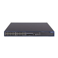
H3C S5500-52C-PWR-EI Installation Manual (96 pages)
S5500-EI Series Ethernet Switches
Brand:
H3C
| Category:
Switch
| Size: 2 MB
Table of Contents
About this Manual
3
Table of Contents
5
Chapter 1 Product Overview
8
Introduction
8
S5500-28C-Ei
9
Appearance
9
Front Panel
10
Rear Panel
10
Power Supply System
10
Cooling System
11
Leds
11
S5500-28C-Ei-DC
14
Appearance
14
Front Panel
15
Rear Panel
15
Power System
15
Cooling System
16
Leds
16
S5500-52C-Ei
19
Appearance
19
Front Panel
20
Rear Panel
20
Power Supply System
20
Cooling System
21
Leds
21
S5500-28C-Pwr-Ei
21
Appearance
21
Front Panel
21
Rear Panel
22
Power Supply System
22
Cooling System
22
Leds
22
S5500-52C-Pwr-Ei
26
Appearance
26
Front Panel
27
Rear Panel
27
Power Supply System
28
Cooling System
28
Leds
28
S5500-28F-Ei
28
Appearance
28
Front Panel
29
Rear Panel
29
Power System
29
Cooling System
30
Leds
30
System Specifications of the S5500-EI Series
33
Pluggable Modules
35
Optional Interface Modules
36
Description of Leds on Extended Modules
37
CX4 Cable
37
Chapter 2 Installation Preparations
38
Safety Precautions
38
Installation Site
38
Temperature/Humidity
38
Cleanness
39
Electromagnetic Susceptibility
39
Laser Safety
40
Installation Tools
40
Chapter 3 Installation
41
Installing the Switch into a 19-Inch Cabinet
41
Introduction to Mounting Ears
42
Introduction to Guide Rails
43
Using Front Mounting Ears to Install the Switch
44
Using Front Mounting Ears and a Tray
45
Using Front and Rear Mounting Ears
45
Using Front Mounting Ears and Guide Rails
48
Mounting the Switch on a Workbench
50
Connecting the Power Cables and the Grounding Cable
51
Connecting the AC Power Cable
51
Connecting the DC Power Cable
52
Connecting the Grounding Cable
57
Connecting the Console Cable
59
Console Cable
59
Connection Procedure
60
Installing and Removing Optional Interface Modules
60
GE XFP Interface Module
61
Short-Haul Dual-Port 10 GE CX4 Interface Module
63
Installing and Removing the Dedicated CX4 Cable
64
Installing the Dedicated CX4 Cable
64
Removing the Dedicated CX4 Cable
64
Verifying the Installation
64
Chapter 4 Initial Power-On
66
Setting up the Configuration Environment
66
Connecting the Console Cable
66
Setting Terminal Parameters
66
Booting the Switch
70
Checking before Power-On
70
Powering on the Switch
70
Changing the Boot Mode
73
Chapter 5 Boot ROM and Host Software Loading
76
Introduction to Loading Modes
76
Local Software Loading
76
Boot Menu
77
Loading Software Using Xmodem through the Console Port
78
Loading Software Using TFTP through an Ethernet Port
84
Loading Software Using FTP through Ethernet Port
86
Remote Software Loading
87
Remote Loading Using FTP
87
Remote Loading Using TFTP
89
Chapter 6 Maintenance and Troubleshooting
90
Software Loading Failure
90
Password Loss
90
User Password Loss
90
Bootrom Password Loss
91
Power Supply Failure
91
Configuration System Failure
91
Appendix A Lightning Protection of the Switch
93
Advertisement
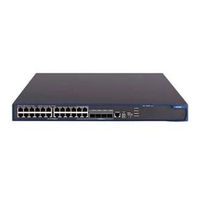
H3C S5500-52C-PWR-EI Installation Manual (95 pages)
S5500-EI Series Ethernet Switches
Brand:
H3C
| Category:
Switch
| Size: 3 MB
Table of Contents
About this Manual
3
Documentation Feedback
4
Obtaining Documentation
4
Related Documentation
4
Table of Contents
6
1 Product Overview
9
Overview
9
S5500-52C-Ei··································································································································1
10
Introduction to S5500-EI Series Ethernet Switches
11
S5500-28C
11
S5500-28C-Ei
13
S5500-28C-Pwr
13
S5500-52C-Pwr
13
S5500-28F
16
Ports
18
Console Port
18
10/100/1000Base-T Ethernet Port
18
SFP Port
18
Combo Port
20
Leds
21
System Status LED
21
Hot Swappable Power Module Status Leds
21
S5500-28F-Ei ··································································································································1
21
RPS Status LED
22
Port Mode LED
22
Seven-Segment LED
23
Ports ······················································································································································1
23
10/100/1000Base-T Auto-Sensing Ethernet Port Status LED
24
Leds······················································································································································1
24
SFP Port Status LED
25
Interface Module Status LED
25
Optional Interface Modules
25
Dual-Port GE SFP Interface Module
26
Short-Haul Dual-Port 10 GE CX4 Interface Module
27
Dual-Port 10 GE SFP+ Interface Module
28
Dual-Port 10 GE XFP Interface Module
30
One-Port 10 GE XFP Interface Module
31
Description of Leds of Interface Modules
31
2 Preparing for Installation
33
Safety Precautions
33
Installation Site
33
Temperature/Humidity
33
Cleanness
33
Electromagnetic Susceptibility
34
Laser Safety
34
Installation Tools
35
3 Installing the Switch
36
Installation Flow of the Switch
36
Installing the Switch into a 19-Inch Rack Using Mounting Brackets
37
Installation Modes
37
Introduction to Mounting Bracket
38
Introduction to Guide Rail
39
Use Front Mounting Brackets to Install a Switch
39
Use Front Mounting Brackets and a Tray to Install a Switch
40
Use Front and Rear Mounting Brackets to Install a Switch
41
Use Front Mounting Brackets and Guide Rails to Install a Switch
44
Mounting the Switch on a Workbench
46
Connecting the Grounding Cable
46
When a Grounding Strip Is Available
47
Where a Grounding Conductor Can be Buried
48
In Other Installation Sites
49
Installing a Power Module
50
Installing the Power Module
50
Removing the Power Module
51
Connecting the Power Cords
52
Connecting the AC Power Cord
52
Connecting the -48V DC Power Cord
53
Connecting the RPS Power Cord
54
Installing an Interface Module
56
Installing an Interface Card
56
Removing an Interface Module
57
Installing Dedicated CX4/SFP+ Cable
58
Removing Dedicated CX4/SFP+ Cable
58
Installing Switches for an IRF
58
Installation Flow for an IRF
59
Drawing a Plan for an IRF with Switches
60
Verifying the Installation
63
4 Starting and Configuring the Switch
64
Setting up the Configuration Environment
64
Connecting the Console Cable
64
Console Cable
64
Connection Procedure
65
Setting Terminal Parameters
65
Booting the Switch
68
Checking before Powering on the Switch
68
Powering on the Switch
68
Changing the Startup Mode
71
5 Boot ROM and Host Software Loading
74
Introduction to Loading Modes
74
Loading Software through the Boot ROM Menu
74
Boot Menu
74
Loading Software Using XMODEM through Console Port
76
Loading Software Using TFTP through Ethernet Port
81
Loading Software Using FTP through Ethernet Port
83
Loading Software through CLI
85
Loading Software Using FTP
85
Loading Software Using TFTP
87
6 Maintenance and Troubleshooting
88
Software Loading Failure
88
Password Missing Failure
88
Missing User Password
88
Missing Boot ROM Password
88
Power Supply Failure
89
Fixed Power Module Failure
89
Hot Swappable Power Module Failure
90
Fan Failure
91
Configuration System Failure
91
Appendix A Lightning Protection of the Switch
94
H3C S5500-52C-PWR-EI Quick Start Manual (91 pages)
Brand:
H3C
| Category:
Switch
| Size: 1 MB
Table of Contents
About this Manual
3
Table of Contents
6
Chapter 1 Product Overview
12
Table 1-1 Models of the S5500-EI Series
13
Table 1-2 Mapping between Two Ports Forming a Combo Port
13
S5500-28C-EI Leds
14
Table 1-3 Leds on the Front Panel of the S5500-28C-EI
15
Table 1-4 Leds on the Front Panel of the S5500-28C-EI-DC
20
S5500-52C-EI Leds
26
Table 1-5 Descriptions of the Leds on the Front Panel of
26
S5500-52C-PWR-EI Leds
33
Table 1-6 Description of Leds on the Front Panel of the
33
Table 1-7 System Specifications of the S5500-EI Series
39
Pluggable Modules
43
Table 1-8 Pluggable Modules that the S5500-EI Series Support
44
Optional Interface Modules
45
Figure 1-1 CX4 Cable
46
Table 1-9 Description of the LED for each Extended Module Slot
46
Chapter 2 Installation Preparations
47
Temperature/Humidity
48
Table 2-1 Dust Concentration Limit in the Equipment Room
49
Table 2-2 Harmful Gas Limits in the Equipment Room
49
Electromagnetic Susceptibility
49
Laser Safety
50
Installation Tools
51
Chapter 3 Installation
52
Introduction to Mounting Ears
53
Figure 3-1 Appearance of a Standard Front Mounting Ear
54
Figure 3-2 Appearance of a Rear Mounting Ear
54
Introduction to Guide Rails
55
Table 3-2 Selection of Mounting Ear for the S5500-EI Series
55
Using Front Mounting Ears to Install the Switch
56
Figure 3-3 Appearance of a Guide Rail
56
Figure 3-4 Fix Front Mounting Ears (1)
57
Using Front Mounting Ears and a Tray
58
Figure 3-5 Fix Front Mounting Ears (2)
58
Using Front and Rear Mounting Ears
59
Figure 3-6 Fix Front Mounting Ears and Load-Bearing Screws
59
Figure 3-7 Fix Rear Mounting Ears
60
Figure 3-8 Fix Front and Rear Mounting Ears
61
Figure 3-9 Effect Diagram of Front and Rear Mounting Ear Installation (1)
62
Using Front Mounting Ears and Guide Rails
63
Figure 3-10 Effect Diagram of Front and Rear Mounting Ear Installation (2)
63
Figure 3-11 Install Front Mounting Ears
64
Figure 3-12 Install Guide Rails
64
Figure 3-13 Install Front Mounting Ears and Guide Rails
65
Mounting the Switch on a Workbench
66
Figure 3-14 Effect Diagram of Front Mounting Ear and Guide Rail
66
Connecting the Power Cables and the Grounding Cable
67
Connecting the AC Power Cable
67
Figure 3-15 Power Socket (Recommended)
67
Figure 3-16 Installing AC Power Cable Retainer
68
Connecting the DC Power Cable
69
Figure 3-17 Appearance of the 12V RPS Socket
70
Figure 3-18 12V RPS Power Cable
70
Figure 3-19 12V RPS Power Connector
71
Figure 3-20 12V RPS Port
71
Figure 3-21 Connect the 12V RPS Connector to the Chassis
72
Figure 3-22 Appearance of the 48V RPS Port
73
Figure 3-23 Connect the 48V RPS Connector to the Chassis
74
Figure 3-24 Appearance of the -48V RPS Port
75
Figure 3-25 Connect the 48V RPS Connector to the Chassis
75
Connecting the Grounding Cable
76
Figure 3-26 Ground the Switch through a Grounding Strip
77
Figure 3-27 Ground the Switch by Burying the Grounding Body
78
Figure 3-28 Ground through an AC PE Wire
78
Connecting the Console Cable
79
Console Cable
79
Figure 3-29 Ground through the PGND of a Power Cabinet
79
Connection Procedure
80
Figure 3-30 Console Cable
80
Table 3-3 Console Cable Pinouts
80
Installing and Removing Optional Interface Modules
81
GE XFP Interface Module
82
Figure 3-31 Appearance of a One-Port 10 GE XFP Interface Module
82
Figure 3-32 Front Panel of a One-Port 10 GE XFP Interface Module
82
Figure 3-33 Appearance of a Dual-Port 10 GE XFP Interface Module
83
Figure 3-34 Front Panel of a Dual-Port 10 GE XFP Interface Module
83
Figure 3-35 Install a 10 GE XFP Interface Module
84
Short-Haul Dual-Port 10 GE CX4 Interface Module
86
Installing and Removing the Dedicated CX4 Cable
87
Installing the Dedicated CX4 Cable
87
Removing the Dedicated CX4 Cable
87
Verifying the Installation
88
Chapter 4 Lightning Protection of the Switch
89
Installation of Lightning Arrester for AC Power (Socket Strip with Lightning Protection)
89
Advertisement
H3C S5500-52C-PWR-EI Quick Start Manual (9 pages)
S5500-EI Series, S5500-SI Series
Brand:
H3C
| Category:
Switch
| Size: 0 MB
Table of Contents
Quick Start Guide
1
About this Guide
3
Product Overview
3
Prepare for Installation
3
Safety Recommendations
3
Installation Tools
4
Install the Switch
4
Installation Workflow
5
Connect the Ground Wire
6
Install the Power Module
6
Connect the Power Cord
6
Verify the Installation
7
Connect the Switch to the Network
8
Power on the Switch
8
Advertisement
Related Products
H3C S5500-52C-EI
H3C S5500-52 C-EI
H3C S5500-52C-SI
H3C S5500-52C-SI 48
H3C S5500-52C-PW
H3C S5500-52C-PWR-SI
H3C S5500-58C-HI
H3C S5500-58C-PWR-HI
H3C S5500-52SC-HI
H3C S5500-52C-PWR-E
H3C Categories
Switch
Network Router
Wireless Access Point
Control Unit
Server
More H3C Manuals
Login
Sign In
OR
Sign in with Facebook
Sign in with Google
Upload manual
Upload from disk
Upload from URL