Table of Contents
Advertisement
Quick Links
DV CAMCORDER
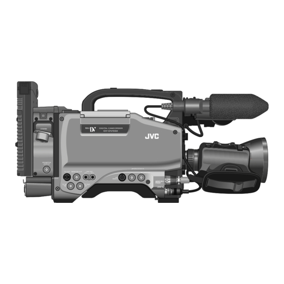
GY-DV550
* The illustration shows the GY-DV550 DV Camcorder with the optional lens viewfinder attached.
Thank you for purchasing this JVC product. Before operating
this unit, please read the instructions carefully to ensure the
best possible performance.
For Customer Use :
Enter below the Serial No. which is located on the body.
Retain this information for future reference.
Model No. GY-DV550
Serial No.
INSTRUCTIONS
This instruction manual is made from 100% recycled paper.
INTRODUCTION
CONTROLS,
INDICATORS AND
CONNECTORS
BASIC SYSTEM
CONNECTIONS AND
ADJUSTMENTS
POWER SUPPLY
PREPARATIONS
SETTING AND
ADJUSTMENTS
BEFORE SHOOTING
SHOOTING
OPERATION
PLAYBACK MODE
TIME CODE
OPERATION
S.S.F. (Super Scene
Finder) FUNCTION
USING EXTERNAL
COMPONENTS
SETUP MENU
FEATURES OF THE
CAMERA SECTION
OTHERS
SC96999-002
Advertisement
Table of Contents

Subscribe to Our Youtube Channel
Related Manuals for JVC GY-DV550U


Summary of Contents for JVC GY-DV550U
- Page 1 DV CAMCORDER GY-DV550 * The illustration shows the GY-DV550 DV Camcorder with the optional lens viewfinder attached. Thank you for purchasing this JVC product. Before operating this unit, please read the instructions carefully to ensure the best possible performance. For Customer Use : Enter below the Serial No.
-
Page 2: Important Safeguards
IMPORTANT SAFEGUARDS 1. Read all of these instructions. 2. Save these instructions for later use. 3. All warnings on the product and in the operating instructions should be adhered to. 4. Unplug this appliance system from the wall outlet before cleaning. Do not use liquid cleaners or aerosol cleaners. Use a damp cloth for cleaning. -
Page 3: Safety Precautions
● Consult the dealer or an experienced radio/TV technician for help. CAUTION CHANGES OR MODIFICATIONS NOT APPROVED BY JVC COULD VOID USER’S AUTHORITY TO OPERATE THE EQUIPMENT. THIS DEVICE COMPLIES WITH PART 15 OF THE FCC RULES. -
Page 4: Main Features
● Recorded video and audio contents are for private use. Other use may infringe on the rights of copyright holders. ● JVC cannot assume liabilities that may derive from the impossibility of normal recording or playback of video or audio due to malfunction of the camcorder or the videocassette. -
Page 5: Table Of Contents
CONTENTS INTRODUCTION MAIN FEATURES ... 4 1. INTRODUCTION 1-1 Main Unit Configuration ... 6 1-2 Precautions for Proper Use ... 7 1-3 Routine and Periodical Maintenance ... 8 1-4 Precautions for Use of Head Cleaning Tape ... 8 1-5 Videocassette to be Used ... 9 1-6 Battery Pack to be Used ... -
Page 6: Introduction
11. USING EXTERNAL COMPONENTS 11-1 Connecting a Video Component with DV Connector 70 11-2 Connecting a PC ... 71 12. SETUP MENU 12-1 VCR Setup Menu ... 72 • VCR Setup Menu Configuration ... 72 • Displaying and Setting VCR Setup Menus ... 73 •... -
Page 7: Precautions For Proper Use
1-2 Precautions for Proper Use ● Supply voltage Make sure that the power is between 11 V and 15 V DC. If the power voltage is too low, abnormal color and increased noise may occur. Do not exceed 15 V DC in any case, or the unit could be damaged. -
Page 8: Routine And Periodical Maintenance
(inspection) to prevent troubles that may be caused by the sudden occurrence of failure. As the replacement, adjustment and servicing of parts require advanced skill and equipment, please consult the person in charge of professional video equipment at your nearest JVC-authorized service agent. Head Cleaning ●... -
Page 9: Videocassette To Be Used
1-5 Videocassette to be Used ● Use JVC’s videocassette tapes marked with MiniDV for this unit. Please use DVM60 or DVM30 type videocassettes. ● Videocassettes cannot be used upside down. ● Avoid storing a videocassette with unevenly wound tape, as this may damage the tape. Rewind it to the beginning before placing a cassette into storage. -
Page 10: Controls, Indicators And Connectors
2. CONTROLS, INDICATORS AND CONNECTORS 2-1 Front Section ZEBRA SKIN AREA AUDIO LEVEL CH-1 Viewfinder mount base, sliding securing ring Mount the viewfinder on the base and secure it using the sliding securing ring. See "Attaching the Viewfinder" on page 33. [VF] Viewfinder connector (6-pin) Connect the cable from the viewfinder here. - Page 11 2-1 Front Section (Cont’d) • The depth of field can be reduced and the lens focusing can be adjusted more accurately. CAUTION: • As the automatic shutter is activated here, flicker may appear on the screen depending on the lighting conditions (such as a fluorescent lamp, etc.) Colors may appear for white subjects.
-
Page 12: Right Side Section
2. CONTROLS, INDICATORS AND CONNECTORS 2-2 Right Side Section [Camera Setting Section] [ALARM] Volume control Turn to adjust the volume of the alarm tone that is output from the monitoring loudspeaker or earphone in case of a warning or other abnormal condition occurring with the GY-DV550. Turn this control anticlockwise to reduce the volume. - Page 13 2-2 Right Side Section [Cont’d] • The iris is placed in automatic mode even if the iris mode switch of the lens is in manual. • The gain will vary continuously to the maximum of +12 dB. The shutter speed will vary continuously to the minimum of 1/240 of a second.
- Page 14 2. CONTROLS, INDICATORS AND CONNECTORS 2-2 Right Side Section (Cont'd) [VCR Setting Section] OPERATE/WARNING RESET MONITOR SELECT FILTER CH-1 ALARM 3200k CH-2 5600k+1/8ND 5600k+1/64ND SHUTTER STATUS MONITOR MENU AUDIO CH-1 CH-2 LEVEL AUTO IRIS FULL AUTO BLACK LOLUX BACK L STRETCH NORMAL NORMAL...
- Page 15 2-2 Right Side Section (Cont'd) [Video setting] [VTR INPUT] VTR input setting switch Select whether to record camera images or composite video from an external device connected to the GENLOCK/AUX IN connector 8 on page 18 with this unit. CAM: Camera images are recorded Synchronous signals can be inputted to the GENLOCK/AUX IN connector.
- Page 16 2. CONTROLS, INDICATORS AND CONNECTORS 2-2 Right Side Section (Cont'd) [VCR Display Section] RESET MONITOR SELECT FILTER CH-1 ALARM 3200k CH-2 5600k+1/8ND 5600k+1/64ND SHUTTER STATUS MONITOR MENU CH-1 AUTO IRIS FULL AUTO BLACK LOLUX BACK L STRETCH NORMAL NORMAL SPOT L COMPRESS OPERATE [OPERATE/WARNING] indicator...
- Page 17 2-2 Right Side Section (Cont'd) Tape transport direction indicators One of the indicators lights according to the REV FWD tape transport direction. is displayed in the record-pause mode and in the still picture mode. Remaining Battery Power Display The 7-dot segment bar display shows the remaining battery power.
-
Page 18: Left Side Section
Setup menu No. 050 REMOTE SELECT to LOCAL or IEEE1394. • When connecting a nonlinear editing device, set to IEEE1394+RS232C. For details, please consult your JVC dealer. Note: If you make an error in the setting, disconnect the connector cable before performing setting again. -
Page 19: Top Section
2-4 Top Section PUSH OPEN [EJECT] switch Slide to the side when inserting or ejecting the videocassette. Sliding this switch opens the cassette cover. If the switch is moved while the power is off, the cassette cover opens but it is not possible to insert or eject the cassette. Operation cover Open this cover when operating in the playback mode. -
Page 20: Adapter Section
2. CONTROLS, INDICATORS AND CONNECTORS 2-5 Adapter Section FILTER 3200k 5600k+1/8ND 5600k+1/64ND SHUTTER STATUS MENU AUTO IRIS FULL AUTO BACK L NORMAL SPOT L [POWER] power source setting switch The power source to this unit is selected using this switch. When turning on the power, set this switch first. - Page 21 [PROMPTER OUTPUT] prompter output connector Return video signals of the external VCR or signals inputted to the AUX input connector of the camera remote control unit are outputted through VTR/RM multi-pin connector 8. 2. CONTROLS, INDICATORS AND CONNECTORS DV CAMCORDER VTR/RM GY-DV550 PROMPTER OUTPUT...
-
Page 22: Rear Section
2. CONTROLS, INDICATORS AND CONNECTORS 2-6 Rear Section LINE LINE +48V FRONT EARPHONE AUDIO IN REAR OUTPUT [DV] connector Using a DV cable (optional), a digital video component with DV connector can be connected here. This connector is used for output of the DV signal or to input the VCR control signal from the digital video component with DV connector. - Page 23 [INTERCOM] intercom input terminal (XLR 5-pin) Input terminal for the intercom headset. Connect the JVC Intercom KA-310 to this terminal. This terminal is enabled when the VTR/RM connector (26- pin) on page 21 is connected to the camera control unit.
-
Page 24: Counter Display Contents
2. CONTROLS, INDICATORS AND CONNECTORS 2-7 Counter Display Contents OPERATE/WARNING CH 1 AUTO OFF DEW OVER RESET 40 30 0 dB SERVO CH 2 OVER SLAVE HOLD MONITOR AUD LOCK WIDE SELECT MENU CH-1 BATT REMAIN REV FWD CH-2 Counter display Tape counter display “CTL”... -
Page 25: Lens (Optional)
2-8 Lens (optional) [S14 x 7.3B12] u i o FOCUS ring Manual focus ring. ZOOM lever/ring This is the manual zoom ring equipped with a zoom lever. To adjust the zoom manually, turn the zoom mode knob @ to position "M". IRIS ring Manual iris ring. -
Page 26: Inch Viewfinder (Optional)
2. CONTROLS, INDICATORS AND CONNECTORS 2-9 1.5-Inch Viewfinder (optional) [VF-P115B] Stopper screw This screw prevents the viewfinder from coming off the camera. Mounting guide To attach on the camera. Connector Connect to the camera. [CONT] contrast adjustment To adjust the contours of the viewfinder image. [BRIGHT] brightness adjustment To adjust the brightness of the viewfinder. -
Page 27: Indications In Viewfinder
2-10 Indications in Viewfinder WARNING LED INDICATORS INSIDE THE VIEWFINDER BATT ALARM BATT REC/ALARM Lamp Lamp VIEWFINDER SCREEN DISPLAY The following indications are displayed on the viewfinder screen. (However, this information is not displayed while the VCR section is playing back a tape.) Status screens (screens for use in checking the current camera settings) Alarm message display... - Page 28 2. CONTROLS, INDICATORS AND CONNECTORS 2-10 Indications in Viewfinder (Cont'd) ACCU - FOCUS Status 0 ● Status 0 Display Position Display ACCU-FOCUS SKIN AREA IEEE 1394 Event display 7 Event display ... Not displayed during external video signal input or IEEE1394 input. Event is displayed in the viewfinder for only about 2 seconds when any of the following switches is operated.
- Page 29 2-10 Indications in Viewfinder (Cont'd) ● Status 1 In addition to the information on the Status 0 screen, this screen displays audio indicators and information on remaining tape, voltage and lens F-number (or FILTER POSITION). Display position Display (Example) CH1- - - - + - - CH2- - - - + - - STBY SAVE...
- Page 30 2. CONTROLS, INDICATORS AND CONNECTORS 2-10 Indications in Viewfinder (Cont'd) Alarm Message Display ACCU - FOCUS Alarm message display 1 Alarm message display 2 CH1 - - - - - + - - CH2 - - - - - + - - F 5 .
- Page 31 2-10 Indication in Viewfinder (Cont'd) Safety Zone Two types of safety zone items can be displayed in the viewfinder. Select the required one with the SAFETY ZONE item on the VF DISPLAY menu screen. The CENTER MARK item can be used to select whether the safety zone center mark indicator should be displayed or not (ON/OFF).
-
Page 32: Basic System Connections And Adjustments
DOLLY TP-P205 HZ-FM13 cannot be used with S14X7.3B12/U. Please use the Focus Manual Unit (FMM-8, CHF-3, CFC-12-990) manufactured by Fujinon. VIEWFINDER VF-P400 VF HOLDER KA-A40 BATTERY HOLDER BH-P27 DV CAMCORDER OPERATE/WARNING LIGHT RESET MODE MONITOR INCOM SELECT COUNTER FILTER CH-1... -
Page 33: Attaching The Zoom Lens (Optional)
3. BASIC SYSTEM CONNECTIONS AND ADJUSTMENTS 3-2 Attaching the Zoom Lens (optional) Hole Mount ring When unplugging the cable connector, first remove the lens itself. Then grasp this portion and pull straight out. 3-3 Attaching the Viewfinder (optional) Sliding securing ring Mounting guide Stopper screw... -
Page 34: Attaching The Microphone (Provided)
3. BASIC SYSTEM CONNECTIONS AND ADJUSTMENTS 3-4 Attaching the Microphone (provided) Provided Microphone 1.3. 3-5 Attaching the Microphone (optional) 2. 4. KA-A50 Microphone holder AUDIO IN FRONT Microphone MV-P615 connector cable Connecting the provided microphone to the viewfinder. The provided microphone is a phantom microphone. Loosen the stopper screw on the viewfinder. -
Page 35: Attaching The Tripod Base (Provided)
BACK L STRETCH NORMAL NORMAL SPOT L COMPRESS OPERATE 3-7 Attaching the 4-inch Viewfinder (Optional) mount screw stopper pin KA-A40 PUSH DV CAMCORDER VTR/RM GY-DV550 PROMPTER OUTPUT GENLOCK/AUX IN LINE OUT Y/C OUT MONITOR OUT VIDEO OUT CH-1 CH-2 REMOTE... -
Page 36: Inserting And Replacing Backup Lithium Batteries
3. BASIC SYSTEM CONNECTIONS AND ADJUSTMENTS 3-8 Inserting and Replacing Backup Lithium Batteries The GY-DV550 uses a lithium battery for backup of the time code data and time date data. Install the provided lithium battery before actually using the unit. ●... -
Page 37: Power Supply
COMPRESS OPERATE OPERATE switch 4-1 AC Operation Use the JVC AA-P250 AC power adapter (max. rated output 12.5 V DC, 3.5 A) as the AC power supply. AA-P250 DC cable AC power adapter Precautions for Connection with the AC POWER... -
Page 38: Attaching A Flat Shape Type Battery Pack
4. POWER SUPPLY 4-2 Battery Pack Operation (Cont'd) ATTACHING A FLAT SHAPE TYPE BATTERY PACK Lock release lever Open the battery case cover while pushing the lock release lever. Insert the battery pack into the battery case with its electrodes facing the unit. -
Page 39: Using An Anton-Bauer Battery Pack
4-2 Battery Pack Operation (Cont'd) USING AN ANTON-BAUER BATTERY PACK To use an Anton-Bauer battery pack (Propack 13/14, Trimpack 13/14, Magnum 13/14, Compack 13/14 Series), it is necessary to detach the battery case from the GY-DV550 and replace it with the Anton-Bauer battery holder. Use the following battery holder. •... -
Page 40: Remaining Battery Power Display
4. POWER SUPPLY 4-2 Battery Pack Operation (Cont'd) REMAINING BATTERY POWER DISPLAY WARNING indicator OPERATE/WARNING LIGHT MODE RESET MONITOR INCOM SELECT COUNTER FILTER CH-1 ALARM CARBON 3200k DYNAMIC CH-2 5600k+1/8ND 5600k+1/64ND INCOM SHUTTER STATUS LEVEL MONITOR CH-1 CH-2 CH-1 CH-2 AUTO FRONT MENU... -
Page 41: Preparations
5. PREPARATIONS 5-1 Turning the Power ON FILTER ALARM 3200k 5600k+1/8ND 5600k+1/64ND SHUTTER STATUS MONITOR MENU AUTO IRIS FULL AUTO BLACK LOLUX BACK L STRETCH NORMAL NORMAL SPOT L COMPRESS OPERATE Select the power supplying method to the unit with the POWER switch. •... -
Page 42: Cassette Loading And Unloading
5. PREPARATIONS 5-2 Cassette Loading and Unloading EJECT EJECT switch STOP OPERATE OPERATE switch VTR switch • A cassette cannot be loaded or unloaded while the GY-DV550 is in OPERATE OFF mode. • Use a videocassette tape marked MiniDV. • The videocassette should be held vertical and inserted straight into the slot. Loading the Cassette Set the OPERATE switch to ON. -
Page 43: Setting The Date And Time
5-3 Setting the Date and Time The date and time of the built-in clock should be set. Powered by the backup lithium battery, the set date and time data continue to count even when the power is switched off. Whether to display the set date and time data on the viewfinder and whether to record the data on the sub-time code area of the tape during recording can be set in DISPLAY item of the Camera TIME DATE menu screen. -
Page 44: Setting And Adjustments Before Shooting
6. SETTING AND ADJUSTMENTS BEFORE SHOOTING 6-1 Camera Settings RESET MONITOR SELECT FILTER CH-1 ALARM 3200k CH-2 5600k+1/8ND 5600k+1/64ND SHUTTER STATUS MONITOR MENU AUTO IRIS FULL AUTO BLACK LOLUX BACK L STRETCH NORMAL NORMAL SPOT L COMPRESS OPERATE AUTO IRIS FULL AUTO BLACK LOLUX... -
Page 45: Viewfinder Adjustment
Display the camera built-in color bar signal on the video monitor and adjust the colors, contrast and brightness. Connect a color video monitor to the MONITOR OUT connector of the GY-DV550. DV CAMCORDER GY-DV550 Set the OUTPUT switch to BARS to output the color bar signal (SMTPE type color bars). -
Page 46: Back Focus Adjustment
6. SETTING AND ADJUSTMENTS BEFORE SHOOTING 6-5 Back Focus Adjustment 4. 6. Siemens star chart It is only necessary to perform this when the lens is attached for the first time or when focusing is not correct in both the telephoto and wide-angle positions. -
Page 47: White Balance Adjustment
6. SETTING AND ADJUSTMENTS BEFORE SHOOTING 6-6 White Balance Adjustment Since the color of light (color temperature) varies depending on the light source, it is necessary to re-adjust the white balance when the main light source illuminating the subject changes. Note: When a subject illuminated by a halogen lamp with a color temperature of 3,200K is shot while the color temperature conversion filter setting is set to 5,600K + ND, a proper white balance adjustment and (FAW) Full Time Auto White balance may not be... -
Page 48: Mixing Characters To Monitor Out
6. SETTING AND ADJUSTMENTS BEFORE SHOOTING 6-7 Mixing Characters to MONITOR OUT PUSH DV CAMCORDER VTR/RM GY-DV550 PROMPTER OUTPUT LINE OUT Y/C OUT MONITOR OUT CH-1 CH-2 REMOTE TC IN TC OUT MONITOR OUT Color video monitor When mixing characters in the MONITOR OUT connector video, set CHARACTER in the Camera SETUP MENU screen to ON. -
Page 49: Switch Settings Of The Vcr Section
6. SETTING AND ADJUSTMENTS BEFORE SHOOTING 6-8 Switch Settings of the VCR Section FILTER ALARM 3200k 5600k+1/8ND 5600k+1/64ND SHUTTER STATUS MONITOR MENU AUTO IRIS FULL AUTO BLACK LOLUX BACK L STRETCH NORMAL NORMAL SPOT L COMPRESS OPERATE Selecting the video input signals Video signals recorded on this unit is selected using the VTR INPUT switch. -
Page 50: Audio Input Signal Selection
6. SETTING AND ADJUSTMENTS BEFORE SHOOTING 6-9 Audio Input Signal Selection ZEBRA SKIN AUTO AREA WHITE ACCU FOCUS AUDIO TAKE LEVEL CH-1 AUDIO IN FRONT connector The GY-DV550 is provided with the AUDIO INPUT connector on the front section and the AUDIO INPUT connectors at the rear section for audio input. -
Page 51: Audio Input Level Adjustment
6. SETTING AND ADJUSTMENTS BEFORE SHOOTING 6-10 Audio Input Level Adjustment ZEBRA SKIN AUTO AREA WHITE ACCU FOCUS AUDIO TAKE LEVEL CH-1 CH-1 audio input level control CH-1 audio input level control For each audio channel, use the AUDIO SELECT switches to select whether the audio input level adjustment should be set to AUTO mode or MANUAL mode. -
Page 52: Monitoring Audio During Recording
6. SETTING AND ADJUSTMENTS BEFORE SHOOTING 6-11 Monitoring Audio during Recording ALARM control The audio input during recording, in record-pause or stop mode can be monitored through the monitoring loudspeaker or earphone. • The monitoring audio is not output from the loudspeaker while the EARPHONE jack is in use. -
Page 53: Shooting Operation
7. SHOOTING OPERATION 7-1 Basic Recording Operation CH 1 OVER 40 30 0 dB CH 2 OVER SLAVE AUD LOCK WIDE MENU EJECT switch EJECT OPERATE/WARNING RESET MONITOR SELECT FILTER CH-1 ALARM 3200k CH-2 5600k+1/8ND 5600k+1/64ND SHUTTER STATUS MONITOR MENU CH-1 AUDIO CH-2... - Page 54 7. SHOOTING OPERATION 7-1 Basic Recording Operation (Cont'd) ZEBRA SKIN AREA AUDIO LEVEL CH-1 OPERATE BATT ALARM Note: ● The unit enters stop mode at tape-end automatically, and if kept longer than 3 minutes or 30 minutes in this mode, SAVE mode is maintained.
-
Page 55: Vcr Save Mode
7-2 VCR Save Mode RESET MONITOR SELECT FILTER CH-1 ALARM 3200k 5600k+1/8ND CH-2 5600k+1/64ND SHUTTER STATUS MONITOR MENU CH-1 AUTO IRIS FULL AUTO BLACK LOLUX BACK L STRETCH NORMAL NORMAL SPOT L COMPRESS OPERATE switch Viewfinder VCR operation status display CH1 - - - - - + - - STBY CH2 - - - - - + - -... -
Page 56: Checking Recorded Contents In Record-Pause Mode
7. SHOOTING OPERATION 7-4 Checking Recorded Contents in Record-Pause Mode * During recording check, the following indications will appear if the error rate increases due to head clogging, etc. • “RF” appears on the display panel. • “HEAD CLOG” appears on the counter display. •... -
Page 57: Recording External Video Signals
7-5 Recording External Video Signals PUSH DV CAMCORDER VTR/RM GY-DV550 PROMPTER OUTPUT GENLOCK/AUX IN LINE OUT Y/C OUT MONITOR OUT CH-1 CH-2 REMOTE TC IN TC OUT GENLOCK/AUX IN Other than camera images, composite video signals from an external device connected to the GENLOCK/AUX IN connector can also be recorded with this unit. -
Page 58: Recording With An External Vcr
Connector S-VHS 14-pin BR-S405 26-pin BR-D40+SA-S40 For the connection of other VCRs, contact your nearest JVC dealer. Settings Selecting the power source Set the POWER switch to DC IN/BATT. CAUTION: It is not possible to supply power to the main unit from an external VCR through the VTR/RM multi-pin connector. - Page 59 7-6 Recording with an External VCR (Cont'd) FILTER ALARM 3200k 5600k+1/8ND 5600k+1/64ND SHUTTER STATUS MONITOR MENU AUTO IRIS FULL AUTO BLACK LOLUX BACK L STRETCH NORMAL NORMAL SPOT L COMPRESS OPERATE VTR switch OPERATE switch Operation Set the OPERATE switch to ON. •...
-
Page 60: Playback Mode
8. PLAYBACK MODE 8-1 Playback Procedure FILTER ALARM 3200k 5600k+1/8ND 5600k+1/64ND SHUTTER STATUS MONITOR MENU AUTO IRIS FULL AUTO BLACK LOLUX BACK L STRETCH NORMAL NORMAL SPOT L COMPRESS OPERATE OPERATE switch Operation Set the POWER switch to DC IN/BATT. and set the OPERATE switch to ON. -
Page 61: Fast-Forward, Rewind
8-2 Fast-Forward, Rewind FILTER ALARM 3200k 5600k+1/8ND 5600k+1/64ND SHUTTER STATUS MONITOR MENU AUTO IRIS FULL AUTO BLACK LOLUX BACK L STRETCH NORMAL NORMAL SPOT L COMPRESS OPERATE Press the FF button in stop mode to fast forward the tape. Press the REW button in stop mode to rewind the tape. Press the STOP button to stop fast forwarding or rewinding. -
Page 62: Time Code Operation
9. TIME CODE OPERATION The GY-DV550 records SMPTE-standard time codes and user's bits. In the play or record mode, the reproduced time codes or user's bits are shown on the counter display. The LTC signal from the built-in time code generator is output through the TC OUT connector. In the play mode, the time code recorded on the tape is not output through the units connectors. -
Page 63: Time Code Presetting Procedure
9-2 Presetting and Recording of Time Code (Cont’d) TIME CODE PRESETTING PROCEDURE HOLD button AUDIO CH-1 CH-2 LEVEL CH-1 CH-2 CH-1 AUTO FRONT MANUAL REAR AUDIO SELECT AUDIO INPUT VTR SELECT TC GENE. CONTINUE INSTR- PRST UCTION PARA FREE MANUAL REGEN LITHIUM BATT. -
Page 64: Recording Time Codes By Slave-Locking The Built-In Time Code Generator With External Tcg
Note : Do not connect or disconnect slaves during recording as this may disturb the servo lock. Multi-Camcorder Master-Slave Connection When there is only one slave GY-DV550, connect it as indicated in the figure below. When connecting several GY-DV550s as slaves, input the REF video signal to GENLOCK/AUX IN connectors of all these units from the sync signal generator. -
Page 65: Recording Time Codes In Continuation Of Time Codes Recorded On Tape
9-4 Recording Time Codes in Continuation of Time Codes Recorded on Tape The GY-DV550 also incorporates a time code reader. Therefore, when the unit enters record mode from record-pause mode, it can read the time code data recorded on the tape and record time codes in continuation of the existing data. The recorded user's bit data is identical to the user's bit data recorded on tape. -
Page 66: Super Scene Finder) Function
10. S.S.F. (Super Scene Finder) FUNCTION 10-1 Explanation of the S.S.F. Function During recording, the S.S.F. function records the time code data at the point of time of a desired recorded scene in the unit's memory. Using the S.S.F. data stored in memory during after-processing of the recorded image allows efficient use of the tape. The S.S.F. -
Page 67: How To Use The S.s.f. Function
10-2 How to Use the S.S.F. Function CUE Mode Set the S.S.F. mode as CUE mode. Set the VCR Setup Menu item No. 398 S.S.F. MODE to "CUE". See page 75. • The CUE mode is indicated in the lower part of the Status 1 screen in the viewfinder. -
Page 68: Deleting S.s.f. Data
10. S.S.F. (Super Scene Finder) FUNCTION 10-3 Deleting S.S.F. Data OPERATE/WARNING RESET MONITOR SELECT FILTER CH-1 ALARM 3200k CH-2 5600k+1/8ND 5600k+1/64ND SHUTTER STATUS MONITOR MENU AUDIO CH-1 LEVEL AUTO IRIS FULL AUTO BLACK LOLUX BACK L STRETCH NORMAL NORMAL SPOT L COMPRESS OPERATE NG button... -
Page 69: Writing S.s.f. Data To Tape
10-5 Writing S.S.F. Data to Tape STOP LOG button REW button OPERATE/WARNING RESET MONITOR SELECT FILTER CH-1 ALARM 3200k CH-2 5600k+1/8ND 5600k+1/64ND SHUTTER STATUS MONITOR MENU AUDIO CH-1 CH-2 LEVEL AUTO IRIS FULL AUTO BLACK LOLUX BACK L STRETCH NORMAL NORMAL SPOT L COMPRESS... -
Page 70: Using External Components
11. USING EXTERNAL COMPONENTS 11-1 Connecting a Video Component with DV Connector Rear section of GY-DV550 INTERCOM LINE LINE +48V +48V FRONT DC INPUT EARPHONE AUDIO IN REAR OUTPUT DV connector When connecting the GY-DV550 to other component with DV connector, be sure to observe the following procedure. When using the GY-DV550 as playback component Turn ON both units. -
Page 71: Connecting A Pc
TTL ⇔ RS-232C converter cable. Or connect the GY-DV550’s DV connector and the DV connector of the non-linear editing controller using a DV cable. For compatible non-linear editing controller, consult with your JVC dealer. Settings • To remote control the PC or non-linear editing controller by means of RS-232C, set the VCR Setup Menu item No. 050 REMOTE SELECT to "IEEE1394+RS232C". -
Page 72: Setup Menu
12. SETUP MENU 12-1 VCR Setup Menu The setup menus for the VCR section can be set while observing the menu in the viewfinder and on the unit's counter display. The set contents are stored in the memory and retained even after the power is switched OFF. VCR SETUP MENU CONFIGURATION The VCR Setup Menu is a two-layer construction. -
Page 73: Displaying And Setting Vcr Setup Menus
12-1 VCR Setup Menu (Cont'd) DISPLAYING AND SETTING VCR SETUP MENUS FILTER ALARM 3200k 5600k+1/8ND 5600k+1/64ND SHUTTER STATUS MONITOR MENU AUTO IRIS FULL AUTO BLACK LOLUX BACK L STRETCH NORMAL NORMAL SPOT L COMPRESS OPERATE “MENU” indication Viewfinder 0 0 0 : SERVO / SYSTEM 1 0 0 : V I DEO 2 0 0 : AUD I O 3 0 0 : SYSTEM... -
Page 74: Vcr Setup Menu Contents
12. SETUP MENU 12-1 VCR Setup Menu (Cont'd) VCR SETUP MENU CONTENTS Item Group Upper row: Viewfinder display Lower row: Counter display indication SERVO 050: REMOTE SELECT /SYSTEM rnSL 052: STEP SLOW MODE StEP 082: BACK TALLY MODE rtMd 126: INPUT SELECT VIDEO Note:... - Page 75 12-1 VCR Setup Menu (Cont'd) Item Group Upper row: Viewfinder display Lower row: Counter display indication SYSTEM 302: BACK SPACE b-SP 307: LONG PAUSE TIME LGPt 396: BATTERY TYPE bAtt 398: SSF MODE 399: REMOTE FF/REW MODE rEFF TIME CODE 403: U-BIT SLAVE UbSc...
-
Page 76: Camera Menu Screen Flow
12. SETUP MENU 12-2 Camera Menu Screen Flow Camera Menu Screen Flow As illustrated below, the Camera Menu is a menu screen comprising several layers. The first layer of the CAMERA MENU screen is for choosing and setting the menus required in accordance with functions or purposes. The unit also allows the contents of menu settings to be stored in three files (SCENE FILE A, B, OFF). -
Page 77: How To Select From The Camera Menu
12-3 How to Select from the Camera Menu OPERATE/WARNING RESET MONITOR SELECT FILTER CH-1 ALARM 3200k CH-2 5600k+1/8ND 5600k+1/64ND SHUTTER STATUS MONITOR MENU AUDIO CH-1 CH-2 LEVEL AUTO IRIS FULL AUTO BLACK LOLUX BACK L STRETCH NORMAL NORMAL SPOT L COMPRESS OPERATE STATUS button... -
Page 78: Vf Display Screen
12. SETUP MENU 12-4 VF Display Screen Item F.NO/FILTER Sets whether to display the F-number of the lens iris or filter position of the unit on status screen 1. F. NO ... F-number is displayed. FILTER ... Filter position is displayed. OFF ... -
Page 79: Operation Screen
12-5 OPERATION Screen Item ASPECT RATIO Sets the image size of the video signal. LETTER ... LETTER BOX (16:9 aspect ratio) image output. 4:3 ... 4:3 aspect ratio image output. Note: When setting ASPECT RATIO to LETTER, 16:9 screen detection ID signal will not be outputted from the Y/C OUT connector. -
Page 80: Process Screen
12. SETUP MENU 12-6 PROCESS Screen Item MASTER Adjusts the pedestal level (master black), which is the reference of black. BLACK • To increase the pedestal level ... Increase the number. (UP) • To decrease the pedestal level ... Decrease the number. (DOWN) DETAIL Adjusts the detail enhancement level. -
Page 81: Advanced Process Screen
12-7 ADVANCED PROCESS Screen Item COLOR Sets the color matrix MATRIX OFF ... Deactivates the color matrix function ON ... The color reproducibility is enhanced, but noise increases. CAUTION: During the LOLUX operation, COLOR MATRIX is fixed to the OFF setting and "FIX"... -
Page 82: File Manage Screen
12. SETUP MENU 12-9 FILE MANAGE Screen The unit has three files that can be used for storing camera menus. The FILE MANAGE screen is for performing the operations for saving the set CAMERA MENU. • When menu settings are made using SCENE FILE A or B, the contents of the settings will be invalid if the storage operations are not performed on this screen. -
Page 83: Setup Screen
12-10 SETUP Screen Item 26 PIN OUT Other than composite signals, another type of video signals can be outputted from the VTR/RM multi-pin connector. The other output video signal is selected here. Y/C : Outputs Y/C separate signals. RGB : Outputs RGB signals. CPN : Outputs component video signals. -
Page 84: Time Date Screen
12. SETUP MENU 12-11 TIME DATE screen Item DISPLAY For setting whether to display the time and date on the viewfinder. OFF : Time and date are not displayed. ON : Time and date are displayed. When setting to ON, the time and date are recorded on the upper of left of the video. -
Page 85: Resetting Of Camera Menu Setting Values
12-12 Resetting of Camera Menu Setting Values Using the FILE MANAGE screen, the CAMERA MENU settings can be reset to the initial setting values. On the FILE MANAGE screen, select the file of the CAMERA MENU to be reset, and then perform the resetting operation. OPERATE/WARNING LIGHT RESET... -
Page 86: Features Of The Camera Section
13. FEATURES OF THE CAMERA SECTION 13-1 Full-Time Auto White Balance (FAW) - - - OPERAT I ON - - - SCENE F I L E A ASPECT RAT I O : 4 : 3 SHUT TER : STEP : NONE : 0 dB GA I N L GA I N M... -
Page 87: Iris (Brightness) Adjustment
13-2 IRIS (Brightness) Adjustment ADJUSTMENT OF LENS IRIS Iris ring Temporary auto iris button Iris mode switch ZEBRA PATTERN DISPLAY DURING MANUAL ADJUSTMENT ZEBRA SKIN AREA AUDIO LEVEL CH-1 ZEBRA switch 13. FEATURES OF THE CAMERA SECTION The lens iris can be adjusted using any of the following three methods. -
Page 88: Shooting The Screen Image On A Computer Monitor
13. FEATURES OF THE CAMERA SECTION 13-3 Shooting the Screen Image on a Computer Monitor Video monitor OPERATE/WARNING RESET MONITOR SELECT FILTER CH-1 ALARM 3200k CH-2 5600k+1/8ND 5600k+1/64ND SHUTTER STATUS MONITOR MENU AUDIO CH-1 LEVEL AUTO IRIS FULL AUTO BLACK LOLUX BACK L STRETCH... -
Page 89: Gain (Sensitivity) Adjustment
13-4 Gain (Sensitivity) Adjustment The gain should be switched when the brightness is insufficient due to poor lighting conditions. GAIN SWITCHING GAIN switch AUTO IRIS FULL AUTO BLACK LOLUX BACK L STRETCH NORMAL NORMAL SPOT L COMPRESS OPERATE CAUTION: When gain is set to "ALC", gain is boosted automatically as the illumination becomes darker. -
Page 90: Switch Setup According To Illumination And Subject
13. FEATURES OF THE CAMERA SECTION 13-5 Switch Setup According to Illumination and Subject Various switch settings are performed to accommodate the conditions of the illumination and the subject when shooting. SWITCH FUNCTIONS AUTO IRIS LEVEL BLACK stretch/black switch compress setting switch AUTO IRIS FULL AUTO BLACK... -
Page 91: How To Use Skin Tone Detail
13-6 How to Use Skin Tone Detail The contour emphasis in the skin color areas of the video signal can be controlled and made to appear gentle and smooth. OPERATE/WARNING RESET MONITOR SELECT FILTER CH-1 ALARM 3200k CH-2 5600k+1/8ND 5600k+1/64ND SHUTTER STATUS MONITOR MENU... - Page 92 13. FEATURES OF THE CAMERA SECTION 13-6 How to Use Skin Tone Detail (Cont’d) ZEBRA SKIN AREA AUDIO LEVEL CH-1 ZEBRA switch ACCU - FOCUS STATUS 0 Confirming the color tone area adjusted with the Skin Tone Detail function When the ZEBRA switch on the front section is pressed to the “SKIN AREA”...
-
Page 93: Connecting The Local Remote Control Unit
GAMMA TITLE TITLE SET • RM-LP57 : SHUTTER EEI setting GAIN ALC setting SC COARSE SC FINE H PHASE 13. FEATURES OF THE CAMERA SECTION DV CAMCORDER GY-DV550 GENLOCK/AUX IN VIDEO OUT REMOTE AUDIO IN FRONT LENS REMOTE Memo: • If the switch functions for this unit and the local remote control unit are the same, the switch function of the local remote control unit will have priority. -
Page 94: Connecting The Camera Remote Control Unit
To use the camera remote control unit RM-P200, internal adjustments of the RM-P200 are required. It is, therefore, mandatory that you contact the nearest JVC-authorized service agent for inquiry about the adjustments. • RM-P300 ... Cable length is 200m only. - Page 95 13-8 Connecting the camera remote control unit (Cont’d) Operation Set the POWER switch of the camera remote control unit to ON. About 30 seconds after turning the power on, the camera remote control unit will be operative. Memo: After the POWER switch is turned on, the camera remote control unit takes about 30 seconds to prepare for correct communication with this unit.
-
Page 96: Others
In other cases, please consult the person in charge of professional video equipment at your nearest JVC-authorized service agent. Operation : Continues. Remedy : Clean the head with the special head cleaning tape. (See “Precautions for Use of Head Cleaning Tape”... - Page 97 14-1 Troubleshooting (Cont'd) Alarm Indications (Cont'd) Depending on the alarm conditions, the warning indicators in the LCD display, the WARNING indicator, the TALLY lamp, alarm tones and the viewfinder appear as shown in the following table. Alarm Indications TALLY WARNING LCD Display Indicator Lamp...
-
Page 98: Warnings In Viewfinder
14. OTHERS 14-1 Troubleshooting (Cont'd) WARNINGS IN VIEWFINDER °Viewfinder Warning Lamps BATT ALARM Battery lamp BATTERY lamp This red lamp lights under the following circumstance. Lights red : • When the battery voltage becomes too low for the camera to operate. REC/ALARM lamp This lamp lights or blinks green under the following conditions. - Page 99 GY-DV550. Please consult the person in charge of professional video equipment at your nearest JVC-authorized service agent. * If the display operates abnormally, Press the RESET switch inside the lithium battery case, and then set the OPERATE switch to ON again.
-
Page 100: Troubles With Error Code Outputs
Operation stops. All operations situation. Please consult the person are rejected. in charge of professional video equipment at your nearest JVC- Operation stops. All operations authorized service agent. are rejected. Operation stops. All operations are rejected. -
Page 101: Troubles Without Error Code Outputs
14-1 Troubleshooting (Cont'd) TROUBLES WITHOUT ERROR CODE OUTPUTS Symptoms Power cannot be switched ON. Operation buttons on the GY-DV550 don't work. Recording is not possible. Noise interferes with playback video. Sound and picture are disturbed during playback. Time code data is not shown as on- screen-display. -
Page 102: Hour Meter Display
14. OTHERS 14-2 Hour Meter Display The unit can display the accumulated running time of the head drum as hour meter data on the counter display. The hour meter can be displayed by selecting HM (HOUR METER) on the VCR Setup Menu. Use this as a guide for periodical maintenance. See page 8. -
Page 103: Specifications
14-3 Specifications CAMERA SECTION Image pickup devices: 1/2-inch interline CCD x 3 Color separation optical system: F1.4 3-color separation prism Number of effective pixels: Approx. 380,000 pixels ((H) 768 x (V) 494) Color system : NTSC (R-Y, B-Y encoder) Color bars : SMPTE color bar Sync system : Internal sync (built-in SSG) -
Page 104: Optional Accessories
14. OTHERS 14-3 Specifications OPTIONAL ACCESSORIES Viewfinder : VF-P115B, VF-P116 Power zoom lens : S14 x 7.3B12, S16 x 6.7B12 S19 x 6.5B12 (FUJINON) YH14 x 7.3K12, YH18 x 6.7K12 (CANON) AC power adapter : AA-P250 Microphone : MV-P615 Microphone holder : KA-A50 EXTERNAL DIMENSIONS (unit: mm) ZEBRA... - Page 105 ® is a registered trademark owned by VICTOR COMPANY OF JAPAN, LTD. ® is a registered trademark in Japan, the U.S.A., the U.K. and many other countries. © 2000 VICTOR COMPANY OF JAPAN, LIMITED VICTOR COMPANY OF JAPAN, LIMITED Printed in Japan SC96999-002...
Need help?
Do you have a question about the GY-DV550U and is the answer not in the manual?
Questions and answers