
Related Manuals for SKF LINCOLN ZPU 01 Version E


Summary of Contents for SKF LINCOLN ZPU 01 Version E
- Page 1 Installation instructions Lubrication pump following machinery directive 2006/42/EC ZPU 01/ ZPU 02 Version E Version V Version F 951-171-016-EN Version 03 2018/11/30...
- Page 2 EC Declaration of incorporation EC Declaration of incorporation following machinery directive 2006/42/EC, annex II, part 1 B The manufacturer, SKF Lubrication Systems Germany GmbH, Walldorf Facilities, Heinrich-Hertz-Str. 2-8, DE - 69190 Walldorf, hereby declares that the partly completed machinery Designation:...
-
Page 3: Legal Disclosure
The manufacturer shall not be held respon- In order to provide a maximum of safety and sible for damages caused by: Manufacturer's facilities economic viability, SKF carries out detailed ○ non appropriate use, training courses. It is recommended that the Headquarters training courses are attended. -
Page 4: Table Of Contents
Table of contents Table of contents Legal disclosure ...................3 Explanation of symbols and signs ...............6 Safety instructions .................8 Lubricants ................... 17 General safety instructions ..............8 General information ................17 General behaviour when handling the product ........8 Selection of lubricants ................17 Intended use .................... - Page 5 Table of contents Electrical connection ................37 Shutdown and disposal ............... 49 Connection of the lubrication line ............38 13.1 Temporary shutdown ................49 6.5.1 Filling via the reservoir lid ..............39 13.2 Final shutdown and disassembly ............49 13.3 Disposal ....................49 Initial start-up ................40 Inspections prior to initial start-up .............40 Spare parts .................
-
Page 6: Explanation Of Symbols And Signs
Explanation of symbols, signs and abbreviations Explanation of symbols and signs General warning Dangerous electrical voltage Risk of falling Hot surfaces Unintentional intake Crushing hazard Pressure injection Suspended load Electrostatically sensitive components Wear personal protective Wear personal protective Wear personal protective Wear personal protective equipment (goggles) equipment (face shield) - Page 7 Explanation of symbols, signs and abbreviations Abbreviations and conversion factors regarding °C degrees Celsius °F degrees Fahrenheit approx. approximately Kelvin Ounce i.e. that is Newton fl. oz. fluid ounce etc. et cetera hour inch poss. possibly second pounds per square inch if appl.
-
Page 8: Safety Instructions
1. Safety instructions 1. Safety instructions 1.2 General behaviour when handling the 1.1 General safety instructions ○ Responsibilities for different activities product ○ The owner must ensure that safety infor- must be clearly defined and observed. ○ The product may only be used in aware- Uncertainty seriously endangers safety. -
Page 9: Intended Use
1. Safety instructions 1.3 Intended use 1.5 Painting of plastic parts ○ to supply, transport, or store hazardous Supply of lubricants within a centralized lu- Painting of any plastic parts or seals of the substances and mixtures in accordance brication system following the specifications, described products is expressly prohibited. -
Page 10: Modifications Of The Product
1. Safety instructions 1.6 Modiications of the product 1.9 Other applicable documents 1.8 Inspections prior to delivery Unauthorized conversions or modifica- In addition to these instructions, the fol- The following inspections were carried out tions may result in unforeseeable impacts lowing documents must be observed by the prior to delivery: on safety. -
Page 11: Markings On The Product
1. Safety instructions 1.11 Notes related to the type identiica- 1.10 Markings on the product 1.12 Notes related to the CE marking tion plate Unintended intake The type identification plate states important CE marking is effected following the require- (with the reservoir being open) characteristics such as type designation, or- ments of the applied directives: der number, etc. -
Page 12: Persons Authorized To Operate The Pump
1. Safety instructions 1.13 Persons authorized to operate the pump 1.13.1 Operator Prior to commencing the activities, external A person who is qualified by training, know- technicians must be informed by the opera- ledge and experience to carry out the func- tor of the company safety provisions, the tions and activities related to normal opera- applicable accident prevention regulations... -
Page 13: Operation
1. Safety instructions 1.16 Operation ○ Carry out transport using suitable trans- ○ Assemble the product only outside of the The following must be observed during operating range of moving parts, at an port and hoisting equipment on suitable commissioning and operation. adequate distance from sources of heat ways only. -
Page 14: Initial Commissioning / Daily Start-Up
1. Safety instructions ○ Lubricant lines should be primed with ○ All parts are correctly installed regulations and the local connection con- ditions into account. lubricant prior to installation. This makes ○ All warning labels on the product are the subsequent ventilation of the system ○... -
Page 15: Cleaning
1. Safety instructions 1.20 Cleaning ○ Risk of fire and explosion when using inflammable cleaning agents. Only use non-flammable cleaning agents suitable for the purpose. ○ Do not use aggressive cleaning agents. ○ Do not use steam jet or high pressure cleaners. -
Page 16: Residual Risks
1. Safety instructions 1.21 Residual risks Possible in life Residual risk Prevention/ remedy cycle Personal injury / material damage due to Keep unauthorized persons away. No people may remain under suspended loads. Lift parts A, B, C, G, H, K falling of raised parts with suitable and tested lifting devices. -
Page 17: Lubricants
Only lubricants specified for the product may be used. Unsuitable Lubricants are used specifically for certain SKF considers lubricants to be an element lubricants may lead to a failure of application purposes. In order to fulfil their of system design. A suitable lubricant is se- the product. -
Page 18: Material Compatibility
It is possible for lubricants to be tested in the company's laboratory for their suitability for being pumped in centralized lubrication sys- tems (e.g. "bleeding"). Please contact SKF if you have further ques- tions regarding lubricants. You may request an overview of the lubri- cants tested by SKF. -
Page 19: Overview, Functional Description
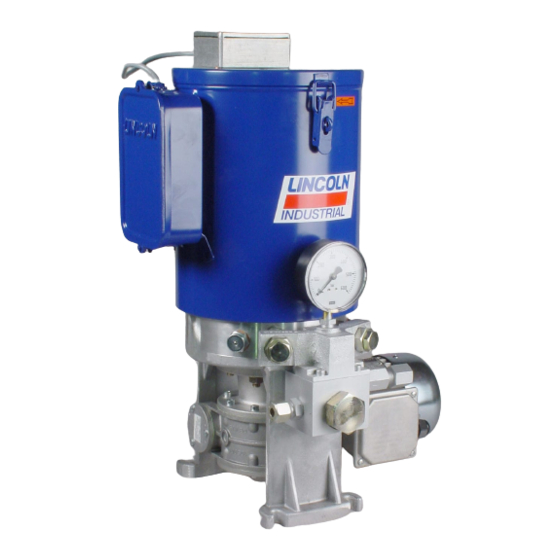
3. Overview, functional description 3. Overview, functional description Overview Fig. 1 Pump types ZPU 01/ ZPU 02 basically consist of the following main components 1 Reservoir with stirring paddle The reservoir contains the lubricant and, if needed, a sensor for low-level indication purposes. - Page 20 3. Overview, functional description Overview version E Fig. 2 Versions Version E: Consists of 1 or 2 pump elements that are fitted directly into the pump housing. ZPU 01/ ZPU 02 pump versions E are used mainly for progressive systems with one or two lubrication circuits.
- Page 21 3. Overview, functional description Overview version V Fig. 3 Version V: Consists of a bridge to combine the lubricant volume and a pressure gauge. ZPU 01/ ZPU 02 pump versions V are used mainly for progressive systems with one lubrica- tion circuit.
- Page 22 3. Overview, functional description Overview version F Fig. 4 Version F: Consists of a bridge to combine the lubricant volume, a filter block, a pressure gauge and a pressure control valve. ZPU 01/ ZPU 02 pump versions F are used mainly for dual-line systems with one lubrica- tion circuit.
-
Page 23: Technical Data
4. Technical data 4. Technical data 4.1 General technical data Range of operating temperatures -25 °C to +70 °C The indicated operating temperature range of the pump presupposes the suitability of the lubricant used for the respective actually existing operating temperature. Using a lubricant not suitable for the actual operating temperature may, in case of low temperatures, result in a defect or failure of the pump due to a too high lubricant viscosity. -
Page 24: Motors 380 - 480 V Ac
4. Technical data 4.2 Motors 380 - 480 V AC Part number Type of motor Manufacturer 245-13913-1 TN 63B Motori Elettrici Rated voltage 230 | 400 265 | 460 V AC Efficiency Circuit Insulation class Rated frequency Type of protection Rated power 0.18 0.21... -
Page 25: Motors 380 - 480 V Ac With Gear
4. Technical data 4.3 Motors 380 - 480 V AC with gear Part number Manufacturer 245-13915-1 Neri Rated voltage 230 | 400 265 | 460 V AC Insulation class Circuit Type of protection Rated frequency Flange Ø 90 Rated power 0.18 0.21 Operating mode... - Page 26 4. Technical data Part number Type of motor Manufacturer 245-13918-1 TN 63B Motori Elettrici Rated voltage 230 | 400 265 | 460 V AC Insulation class Circuit Type of protection Rated frequency Flange Ø 90 Rated power 0.18 0.21 Operating mode Rated speed 1380 1630...
-
Page 27: Motors 500 V Ac
4. Technical data 4.4 Motors 500 V AC Part number Type of motor Manufacturer 245-13919-1 TN 63B Motori Elettrici Rated voltage 290 | 500 V AC Insulation class Type of protection Rated frequency Flange Ø 90 Rated power 0.18 Operating mode Rated speed 1360 Size... -
Page 28: Motors 500 V Ac With Gear
4. Technical data 4.5 Motors 500 V AC with gear Part number Type of motor Manufacturer 245-13921-1 T63B Neri Motori Rated voltage 290 | 500 V AC Insulation class Circuit Type of protection Rated frequency Flange Ø 90 Rated power 0.18 Operating mode Rated speed... - Page 29 4. Technical data Part number Type of motor Manufacturer 245-13923-1 TN 63B Varvel Rated voltage 290 | 500 V AC Insulation class Circuit Type of protection Rated frequency Flange Ø 90 Rated power 0.18 Operating mode Rated speed 1360 Size Nominal current 1.0/0.6 Design...
-
Page 30: Ultrasonic Sensor 664-853Xx-X
4. Technical data 4.6 Ultrasonic Sensor 664-853xx-x Ultrasonic sensor 664-853xx-x Blind zone 0 - 65 mm Scanning range limit 600 mm Detection zone in centimetres Ultrasonic frequency approx. 400 kHz The dark grey areas indicate the Switching frequency 3.7 Hz zone in which the standard reflec- Resolution 0.18 mm... -
Page 31: Tightening Torques
4. Technical data 4.7 Tightening torques All pump versions Pump version V Reservoir with pump housing 8 Nm ± 0.8 Nm Pump cylinder with pump housing 30 Nm ± 3 Nm Ultrasonic sensors with reservoir lid 1.5 Nm ± 0.2 Nm Check valve with pump cylinder 30 Nm ±... -
Page 32: Type Identification Code
4. Technical data 4.8 Type identiication code The type identification code facilitates identification of important equipment features of the product. For type identification code see type identification plate of product. Product designation Pump elements ZPU 01 1 pump element Only pump element(s) ZPU 02 2 pump elements Bridge with pump element(s) and pressure gauge... -
Page 33: Delivery, Returns, And Storage
5.3 Storage storage. This particularly applies for parts made out of plastic and SKF products are subject to the following rubber (embrittlement) as well storage conditions: as for components primed with ○ dry, dust- and vibration-free in closed lubricant (ageing). -
Page 34: Assembly
6. Assembly 6. Assembly 6.2 Place of installation 6.1 General information Protect the product against humidity, Only qualified technical personnel may install dust and vibrations and install it in an the products described in these Instructions. easily accessible position to ensure all During assembly pay attention to the other installations can be carried out following:... -
Page 35: Mechanical Connection
6. Assembly 6.3 Mechanical connection Minimum assembly dimensions Fig. 5 6.3.1 Minimum assembly dimensions Ensure sufficient space for maintenance work or for a possible disassembly of the product by leaving a free space of at least 100 mm into each direction in addition to the stated dimensions. -
Page 36: Installation Bores
6. Assembly 6.3.2 Installation bores Installation bores Fig. 6 The product is fastened on the 4 mounting bores (A) on an even surface of the pump housing. Fastening is done by means of 4 screws type M8 (property class 8.8) 951-171-016 - 36 - Version 03... -
Page 37: Electrical Connection
6. Assembly 6.4 Electrical connection Connection diagrams Fig. 7 WARNING Risk of injury Before carrying out any work on electrical components, take at least the following safety measures: ○ Keep unauthorized persons away. ○ Mark and secure work area. ○ Depressurize the product. ○... -
Page 38: Connection Of The Lubrication Line
6. Assembly 6.5 Connection of the lubrication line ○ The lubricant flow should not be impeded Observe the following installation instruc- CAUTION tions for safe and smooth operation. by the installation of sharp elbows, angle valves, gaskets protruding to the inside, ○... -
Page 39: Filling Via The Reservoir Lid
6. Assembly Filling via the reservoir lid Fig. 8 6.5.1 Filling via the reservoir lid In case of reservoirs with ultra- WARNING sonic sensor: The ultrasonic sensor must not Crushing hazard get in contact with lubricant. on the rotating stirring paddle. Fill- ing via the reservoir lid is allowed The distance between the lubri- only after disconnecting the pump... -
Page 40: Initial Start-Up
7. Initial start-up 7. Initial start-up In order to warrant safety and function, a person assigned by the operator must carry out the following inspections. Immediately eliminate detected deficiencies. Deficiencies may be remedied by an authorized and qualified specialist only. Start-up check list 7.1 Inspections prior to initial start-up Electrical connection carried out correctly. -
Page 41: Operation
8. Operation 8. Operation SKF products operate automatically to the greatest possible extent. Basically, activities during standard opera- tion are limited to the control of the filling level and the timely refilling of lubricant as well as the outside cleaning of the product in case of contamination. -
Page 42: Cleaning
• Thorough cleaning of all outer surfaces uct will be required. Thoroughly remove residues of with a damp cloth. To do so, contact the SKF Customer Service. cleaning agents from the product Make sure to keep the reser- and rinse off with clear water. -
Page 43: Maintenance
10. Maintenance Maintenance Regular and appropriate maintenance is a prerequisite to detect and clear faults in time. The specific timelines have to be determined, verified at regular intervals and adapted, if necessary, by the operator based on the operating conditions. If needed, copy the table for regular maintenance activities. Maintenance check list Activity to be done Electrical connection carried out correctly. -
Page 44: Maintenance Of Gear Unit
10. Maintenance 10.1 Maintenance of gear unit 10.2 Motor maintenance The gear units are largely maintenance-free and primed with synthetic oil. Carry out the 10.2.1 Inspection of the bearings To replace the bearing grease proceed as following activities in the indicated intervals follows: After a longer period of standstill or storage in order to avoid damages. -
Page 45: Troubleshooting
11. Faults Troubleshooting Fault table 1 Fault Possible cause Remedy - Power supply to the pump is interrupted - Superior machine is switched off Check whether one of the indicated faults is present and rem- - Connection cable of pump is loose or defective edy it in the frame of responsibilities. -
Page 46: Repairs
12. Repairs Repairs 12.1 Replace the pump element Mounting of the pump element Fig. 9 WARNING In case of pumps with grease fill- Risk of injury ing, the grease may remain in the Before carrying out any repair reservoir. In case of pumps with work, take at least the following oil filling, the oil must be collected safety measures:... -
Page 47: Pump Version E
12. Repairs 12.1.1 Pump version E Unscrew the pump element Fig. 10 Pump element pressed down Fig. 11 • Fully unscrew the pump element (2) at the hexagon out of the pump. • Press pump element (2) down as shown so that the piston disengages from the notch of the catch ring. -
Page 48: Pump Versions F And V
12. Repairs 12.1.2 Pump versions F and V • Now hold the pump cylinder (7) hori- Correct assembly of the pump elements Fig. 12 • Unscrew the check valve (6) out of the zontally so that the piston of the pump pump cylinder (7). -
Page 49: Shutdown And Disposal
13. Shutdown and disposal Shutdown and disposal 13.1 Temporary shutdown 13.3 Disposal Dispose of or recycle electrical Temporarily shut the system down by: Countries within the European Union components following WEEE ○ switching off the superior machine. directive 2012/19/EU. ○ Disconnecting the product from the Disposal should be avoided or minimized wherever possible. -
Page 50: Spare Parts
14. Spare parts Spare parts The spare parts assemblies may be used exclusively for replacement of identical defective parts. Modifications with spare parts on existing products are not allowed. Fig. 13 14.1 Motors 380 - 480 V AC Designation Qty. Part number Motor for gear M100/M490 | 0.18 kW / 0.21 kW 245-13913-1... -
Page 51: Motors 500 V Ac
14. Spare parts Fig. 15 14.3 Motors 500 V AC Designation Qty. Part number Motor for gear M100/M490 | 0.18 kW 245-13919-1 Motor for gear M049 | 0.25 kW 245-13920-1 Fig. 16 14.4 Motors 500 V AC with gear Designation Qty. -
Page 52: Pump Element For Pump Version E
14. Spare parts Fig. 18 14.6 Pump element for pump version E Designation Qty. Part number Pump element assy. 500-30018-3 Fig. 19 14.7 Pressure control valve for pump version E Designation Qty. Part number Pressure control valve 10 mm / 350 bar 624-25483-1 Pressure control valve 10 mm / 400 bar 624-28073-1... -
Page 53: Bridge Assy. For Version F With One Pump Element
14. Spare parts Fig. 21 14.9 Bridge assy. for version F with one pump element Designation Qty. Part number Bridge assy. for version F with one pump element 350 bar 600-26787-1 Bridge assy. for version F with one pump element 400 bar 600-77912-1 Consisting of: Item 1 Bridge with filter block and pressure gauge... -
Page 54: Bridge Assy. For Version F With Two Pump Elements
14. Spare parts Fig. 24 14.12 Bridge assy. for version F with two pump elements Designation Qty. Part number Bridge assy. for version F with two pump elements 350 bar 600-26788-1 Bridge assy. for version F with two pump elements 400 bar 600-77913-1 Consisting of: Item 1 Bridge with filter block and pressure gauge... -
Page 55: Bridge Assy. For Version V With Two Pump Elements
14. Spare parts Fig. 26 14.14 Bridge assy. for version V with two pump elements Designation Qty. Part number Bridge assy. for version V with two pump elements 350 bar 600-26786-1 Bridge assy. for version V with two pump elements 400 bar 600-77915-1 Consisting of: Item 1 Bridge with filter block and pressure gauge... -
Page 56: Parts For Strainer For Version F
14. Spare parts Fig. 28 14.16 Parts for strainer for version F Designation Qty. Part number Rubber-lined sealing ring Ø 34.3 x 43 x 2 220-12238-3 Coarse strainer 428-21544-1 Fine strainer 428-21545-1 Fig. 29 14.17 Pressure gauge for pump versions V and F Designation Qty. - Page 57 Notes...
- Page 58 951-171-016-EN Version 03 2018/11/30 SKF Lubrication Systems Germany GmbH Walldorf Facilities Heinrich-Hertz-Str. 2-8 DE - 69190 Walldorf Phone: +49 (0) 6227 33-0 Fax: +49 (0) 6227 33-259 E-mail: Lubrication-germany@skf.com www.skf.com/lubrication...
Need help?
Do you have a question about the LINCOLN ZPU 01 Version E and is the answer not in the manual?
Questions and answers