Table of Contents
Advertisement
Quick Links
Advertisement
Table of Contents

Related Manuals for Advantech AFE-R770


Summary of Contents for Advantech AFE-R770
- Page 1 User Manual AFE-R770 AMR Controller...
- Page 2 This product contains a hard copy of the Chinese user manual for China CCC certifi- cation purposes. A PDF of the English user manual can be downloaded from the company website. Please disregard the hard copy Chinese user manual if the prod- uct is not sold and/or installed in China. AFE-R770 User Manual...
- Page 3 No part of this manual may be reproduced, copied, translated, or transmitted in any form or by any means without the prior written permission of Advantech Co., Ltd. The information provided in this manual is intended to be accurate and reliable.
-
Page 4: Product Warranty (2 Years)
Product Warranty (2 Years) Advantech warrants the original purchaser that each of its products will be free from defects in materials and workmanship for two years from the date of purchase. This warranty does not apply to any products that have been repaired or altered by persons other than repair personnel authorized by Advantech, or products that have been subject to misuse, abuse, accident, or improper installation. -
Page 5: Technical Support And Assistance
Technical Support and Assistance Visit the Advantech website at www.advantech.com/support to obtain the latest product information. Contact your distributor, sales representative, or Advantech's customer service center for technical support if you need additional assistance. Please have the following information ready before calling: –... -
Page 6: Ordering Information
If any of the following occurs, have the equipment checked by service person- nel: – The power cord or plug is damaged. – Liquid has penetrated the equipment. – The equipment has been exposed to moisture. AFE-R770 User Manual... -
Page 7: Consignes De Sécurité
21.This product is intended to be supplied by a UL-Listed power supply suitable for use at minimum Tma 65°C (149°F) whose output meets ES1 (or SELV) and output is rated: 9-36 Vdc, 16.6-4.16 A. Please contact Advantech for further informa- tion. - Page 8 1: 1982 n'est pas supérieur à 70 dB (A). AVERTISSEMENT: Cet ensemble d'instructions est donné conformément à la norme CEI 704-1. Advantech décline toute responsabilité quant à l'exactitude des déclarations contenues dans ce. Au moyen d'un cordon d'alimentation connecté à une prise de courant avec mise à...
-
Page 9: Table Of Contents
Table 2.7: COM Port Failsafe Setting........12 Connectors....................13 2.3.1 AFE-R770 External I/O Locations..........13 Figure 2.2 AFE-R770 Front and Rear I/O Connector Diagram.. 13 Figure 2.3 COM Connector............14 Table 2.8: COM Connector Pin Assignments......14 Figure 2.4 Ethernet Connector ..........15 Table 2.9: Ethernet Connector Pin Assignments....... - Page 10 ........27 Introduction ..................... 28 Entering Setup ..................29 3.2.1 Main Setup.................. 29 3.2.2 Advanced BIOS Features Setup..........30 3.2.3 Chipset Configuration ..............63 3.2.4 Security..................85 3.2.5 Boot .................... 87 3.2.6 Save & Exit ................. 88 AFE-R770 User Manual...
-
Page 11: Chapter 1 General Introduction
Chapter General Introduction This chapter details background information on the AFE-R770 series. -
Page 12: Introduction
(-20 ~ 65°C / -4 ~ 149°F). Rugged Multi-Functional Design AFE-R770 adopts an advanced thermal design for its desktop processor solution. All models are fanless and feature various unique features. These include wide operat- ing temperature ranges (-20 ~ 65°C / -4 ~ 149°F), diverse expandability options, and structural strengthening. -
Page 13: Ethernet
Supports IRQ sharing among serial ports under Microsoft COM1, COM2, COM3, COM4: RS-232/422/485 Ethernet LAN1/2/3/4 Intel i226LM I226LM supports up to 10/100/1000/2500Mbps LAN connectors: phone Jack RJ-45 8P 90D (F) Audio Audio Codec: ALC888S-VD2-GR Compliant with HD Audio specifications AFE-R770 User Manual... -
Page 14: Susi 5.0
Hardware monitor CPU temperature / input voltage 2 x CAN bus ports supported by SUSI API Mechanical Specifications 1.4.1 Dimensions With wallmount: 230 x 55 x 215 mm / 9.06 x 2.17 x 8.46 in (W x H x D) AFE-R770 User Manual... -
Page 15: Weight
W/O wallmount: 200 x 55 x 215 mm / 7.87 x 2.17 x 8.46 in (W x H x D) Figure 1.1 AFE-R770 Mechanical Dimensions 1.4.2 Weight Net weight: 2.7 kg (6 lb) Power Requirements 1.5.1 System Power Power Input Range: 9 ~ 36 V ... - Page 16 AFE-R770 User Manual...
-
Page 17: Chapter 2 Hardware Configuration
Chapter Hardware Configuration... -
Page 18: Introduction
2.2.1 Jumper Description You may configure AFE-R770 to match the needs of your application by setting jump- ers. A jumper is a metal bridge used to close an electric circuit. It consists of two metal pins and a small metal clip (often protected by a plastic cover) that slides over the pins to connect them. -
Page 19: Jumper Locations
2.2.3 Jumper Locations AFE-R770 User Manual... -
Page 20: Jumper Settings
Jumper Settings 2.2.4.1 AT/ATX Mode Jumper (PSON1) Table 2.2: PSON1 Auto Power On Setting Part Number 1653004101 Description Pin Header 4x1P 2.0mm 180D(M) DIP 21N12050 Setting Function (1-2) Power Button for Power On (default) (3-4) Auto Power On AFE-R770 User Manual... - Page 21 Table 2.5: COM3 RS232/485/422 selection Part Number 1653003260 Description Pin Header 3x2P 2.0mm 180D(M) DIP 21N22050 Setting Function (1-3) (4-6) RS232 (default) (1-3) (2-4) RS422 (3-5) (2-4) RS485 Note! Settings also need to be configured in the BIOS menu. AFE-R770 User Manual...
- Page 22 2.2.4.6 COM1~4 Port Failsafe Setting(SW_422_1/SW_422_2/SW_422_3/SW_422_4) Table 2.7: COM Port Failsafe Setting Part Number 1600000402 Description DIP SW SMD 8P SPST P=1.27mm W=5.4mm KHS42E Setting Function Switch Off Normal operation (default) Switch ON Enable safe and termination resistor AFE-R770 User Manual...
-
Page 23: Connectors
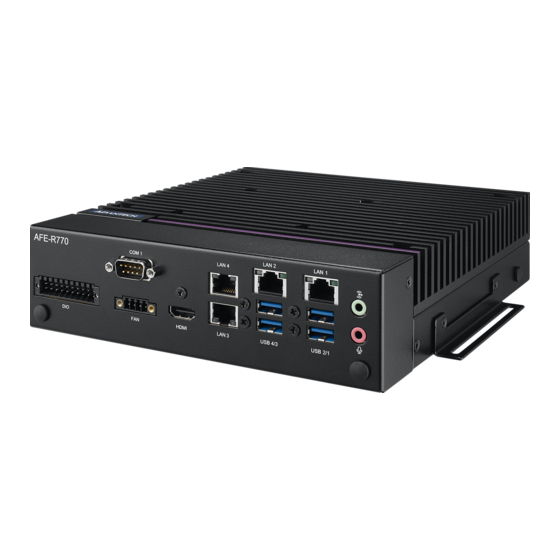
Connectors 2.3.1 AFE-R770 External I/O Locations LAN 1/2/3/4 up to 10/100/1000/2500Mbps USB 3.2 Gen2: USB1~2 USB 3.2 Gen1: USB3~4 RS-232/422/485: COM1/2/3/4 Figure 2.2 AFE-R770 Front and Rear I/O Connector Diagram AFE-R770 User Manual... - Page 24 2.3.1.1 COM Connector AFE-R770 provides up to eight D-sub 9-pin connectors, which offer RS-232/422/485 serial communication interface ports. The default setting is RS-232, and the RS-422/ 485 can be supported via the BIOS settings. Only COM3 supports RI/+5V/+12V; the other COM support RI.
- Page 25 2.3.1.3 Power On/Off Button AFE-R770 has a Power On/Off button with LED indicators on the front side that show “On” (Green LED) and “Off/Suspend” status (Orange LED). The Power button sup- ports dual functions: Soft Power-On/Off (Instant off or Delay 4 Seconds then off), and Suspend.
- Page 26 2.3.1.4 Audio Connector AFE-R770 features one phone jack connector that supports stereo Line-Out or Mic-In audio ports. The audio chip is controlled by ALC888S and compliant with the Azalea standard. Figure 2.6 Audio Connector 2.3.1.5 HDMI Connector An integrated, 19-pin receptacle connector HDMI Type A Interface is provided. The HDMI link supports resolutions up to 4096 x 2160 @ 24 Hz.
- Page 27 2.3.1.6 USB 3.2 - Gen2 and Gen1 AFE-R770 supports 2 x USB 3.2 (Gen2, 10G), and 2 x USB 3.2 (Gen1, 5G). The USB interfaces comply with USB UHCI, Rev. 3.0 standards. Please refer to Table 2.10 for its pin assignments.
- Page 28 2.3.1.8 LED& Remote Switch Connector AFE-R770 provides the remote switch connector for power on/off, power LED, and SATA LED with an external cable. When WDT is enabled, this pin will go low for 1 second. Figure 2.10 LED & Remote Switch Connector Table 2.13: Remote control Connector Pin Assignment...
- Page 29 2.3.1.9 Phoenix Terminal Connector AFE-R770 supports one 3-pin Phoenix terminal power input connector. Connect the positive and negative power cables to the terminals in the power distribution connec- tor correctly at the same time. Figure 2.11 Phoenix Terminal Connector Note! For supply connections use wires suitable for at least 105°C.
- Page 30 Table 2.16: FAN Connector Signal Name +12V FAN_TACH FAN_PWM 2.3.1.12 PC/Vehicle Mode Switch Figure 2.14 P/V Mode Switch Table 2.17: P/V Mode Switch Function Switch to P Operate in PC mode (default) Switch to V Operate in vehicle mode AFE-R770 User Manual...
-
Page 31: Installation
Installation 2.4.1 CPU/Memory Installation Unscrew the 4 spring screws and 4 hex head screws on the top cover, and remove the top cover. Install the CPU (LGA1700) and memory into the system. Replace the top cover. AFE-R770 User Manual... -
Page 32: Remove The Bottom Cover
2.4.2 Remove the Bottom Cover Unscrew the 8 screws on the bottom cover. AFE-R770 User Manual... -
Page 33: Module Installation
2.4.3 M.2 Module Installation Remove the bottom cover (2.4.2). Install the M.2 module with 1 screw (per socket). Replace the bottom cover and fix it in place with 8 screws. AFE-R770 User Manual... -
Page 34: Mounting Kit Installation
Vissez chaque 2 vis (M3x6L) sur les côtés gauche et droit et fixez le système horizontalement. 2.4.5 Wide Operating Temperature Support To make sure the system works well under 0°C (32°F) or over 40°C (104°F), please ensure your peripherals are I-grade. These support wide temperature operation. AFE-R770 User Manual... - Page 35 AFE-R770 User Manual...
- Page 36 AFE-R770 User Manual...
-
Page 37: Chapter 3 Bios Settings
Chapter BIOS Settings... -
Page 38: Introduction
AMIBIOS has been integrated into motherboards for over two decades. With the AMIBIOS Setup program, users can modify BIOS settings and control various sys- tem features. This chapter describes the basic navigation of the AFE-R770 BIOS setup screens. AMI's BIOS ROM has a built-in setup program that allows users to modify the basic system configuration. -
Page 39: Entering Setup
BIOS supports your CPU. If there is no number assigned to the patch code, please contact an Advantech application engineer to obtain an up-to-date patch code file. This will ensure that your CPU’s system status is valid. -
Page 40: Advanced Bios Features Setup
3.2.2 Advanced BIOS Features Setup Select the Advanced tab from the AFE-R770 setup screen to enter the Advanced BIOS Setup screen. Users can select any item in the left frame of the screen, such as CPU Configuration, to go to the sub-menu for that item. Users can display an Advanced BIOS Setup option by highlighting it using the <Arrow>... - Page 41 Performance-core Information Displays the P-core Information. C6DRAM Enable/Disable moving of DRAM contents to PRM memory when the CPU is in C6 state. AFE-R770 User Manual...
- Page 42 Configure Total Memory Encryption (TME) to protect DRAM data from physical attacks. Legacy Game Compatibility Mode When enabled, pressing the scroll lock key will toggle the Efficient-cores between being parked when Scroll Lock LED is on and un-parked when the LED is off. AFE-R770 User Manual...
- Page 43 Enable/Disable usage of SMM_DELAYED MSR for MP sync in SMI. SMM Use Block Indication Enable/Disable usage of SMM_BLOCKED MSR for MP sync in SMI. SMM Use en-US Indication Enable/Disable usage of SMM_ENABLE MSR for MP sync in SMI. AFE-R770 User Manual...
- Page 44 3.2.2.2 Power and Performance – CPU Power Management Control AFE-R770 User Manual...
- Page 45 EPB override over PECI Enable/Disable EPB override over PECI. Enable by sending pcode command 0x2b, subcommand 0x3 to 1. This will allow OOB EPB PECI override control. HWP Lock Enable/Disable HWP Lock support in Misc Power Management MSR. AFE-R770 User Manual...
- Page 46 Enable/disable Energy Performance Gain. Energy Efficient P-state Enable/Disable Energy Efficient P-state feature. Package Power Limit MSR Lock Enable/Disable locking of Package Power Limit settings. Power Limit 1 Override Enable/Disable Power Limit 1 override. AFE-R770 User Manual...
- Page 47 Enable/Disable Power Limit 2 override. Power Limit 2 Power Limit 2 value in milliwatts. Energy Efficient Turbo Enable/Disable Energy Efficient Turbo Feature. This feature will opportunisti- cally lower the turbo frequency to increase efficiency. AFE-R770 User Manual...
- Page 48 Number of P states Sets the number of custom P-states. At least 2 states must be present. AFE-R770 User Manual...
- Page 49 The range is 0-100. Power Limit 3 Lock Power Limit 3 MSR 615h Lock. When enabled, PL3 configurations are locked when the OS is running. When disabled, PL3 configuration can be changed when the OS is running. AFE-R770 User Manual...
- Page 50 CFG Lock Configure MSR 0xE2[15], CFG Lock bit. Overclocking Lock Enable/Disable Overclocking Lock (BIT 20) in FLEX_RATIO(194) MSR. AFE-R770 User Manual...
- Page 51 RC6 (Render Standby) Check to enable render standby support. Maximum GT frequency Maximum GT frequency limited by the user. Disable Turbo GT frequency Enabled: Disables Turbo GT frequency. Disabled: GT frequency is not limited. AFE-R770 User Manual...
- Page 52 3.2.2.3 PCH-FW Configuration ME State When Disabled, ME will be put into ME Temporarily Disabled Mode. Manageability Features State Enable/Disable Intel Manageability features. AFE-R770 User Manual...
- Page 53 When Disabled, ME will not be unconfigured on RTC Clear. Comms hub support Enables/Disables support for Comms Hub. JHI support Enable/Disable Intel® DAL Host Interface Service (JHI). Core BIOS Done Message Enable/Disable Core BIOS Done message sent to ME. AFE-R770 User Manual...
- Page 54 ME FW Image Re-Flash Enable/Disable ME FW Image Re-Flash function. FW Update Enable/Disable ME FW Update function. AFE-R770 User Manual...
- Page 55 TPM Device Selection Configure TPM device. AFE-R770 User Manual...
- Page 56 Set HW-Enforced Anti-Rollback for Current SVN Enable the hardware-enforced Anti-Rollback mechanism for current ARB-SVN value. FW with lower ARB-SVN will be blocked from execution. The value will be restored to disable after the command is sent. AFE-R770 User Manual...
- Page 57 Automatic OEM Key Revocation When enabled, the BIOS will automatically send HECI command to revoke OEM keys. Invoke OEM Key Revocation A Heci command will be send to revoke the OEM key. AFE-R770 User Manual...
- Page 58 Extend CSME Measurement to TPM-PCR Enable/Disable Extend CSME Measurement to TPM-PCR[0] and AMT Config to TPM-PCR[1]. 3.2.2.4 Intel(R) Time Coordinated Computing #AC Split Lock Enable or Disable Alignment Check Exception (#AC). When enabled, this will AFE-R770 User Manual...
- Page 59 Gfx LLC allocation to minimize impact of Gfx workload on LLC. Intel(R) TCC Authentication Intel(R) TCC Authentication determines the key to be used. An OEM Enrolled Key is built in by OEM. A non-OEM Enrolled Key can be added by the user. AFE-R770 User Manual...
- Page 60 Enables or Disables BIOS support for security device. The OS will not show the Security Device. TCG EFI protocol and INT1A interface will not be available. SHA256 PCR Bank Enable or Disable SHA256 PCR Bank. AFE-R770 User Manual...
- Page 61 TPM 1.2 will restrict support to TPM 1.2 devices; TPM 2.0 will restrict support to TPM 2.0 devices; Auto will support both with the default set to TPM 2.0 devices if not found; TPM 1.2 devices will be enumerated. 3.2.2.6 ACPI Settings AFE-R770 User Manual...
- Page 62 Enables or Disables BIOS ACPI Auto Configuration. Enable Hibernation Enables or Disables the system’s ability to hibernate (OS/S4 Sleep State). ACPI Sleep State Select the highest ACPI sleep state the system will enter when the SUSPEND button is pressed. AFE-R770 User Manual...
- Page 63 3.2.2.7 iManager Configuration Serial Port 1~4 Configuration Set Parameters of Serial Port 1~4. Hardware Monitor Monitor hardware status. AFE-R770 User Manual...
- Page 64 Watch Dog Timer Configuration Watch Dog Timer Configuration page. ACPI Report Method Configuration Select ACPI Reporting Method for EC Devices. Digital I/O Configuration Configure the digital I/O pins. 3.2.2.8 S5 RTC Wake Settings AFE-R770 User Manual...
- Page 65 Wake system from S5 Enable or disable system wake on alarm event. 3.2.2.9 Serial Port Console Redirection AFE-R770 User Manual...
- Page 66 Console Redirection Console Redirection Enable or Disable. Legacy Console Redirection Settings Legacy Console Redirection Settings. Console Redirection EMS Console Redirection Enable or Disable. AFE-R770 User Manual...
- Page 67 3.2.2.10 PCI Subsystem Settings Above 4G Decoding Globally Enables or Disables 64-bit capable devices to be decoded in Above 4G Address Space (only if the system supports 64-bit PCI decoding). AFE-R770 User Manual...
- Page 68 If the system has Resizable BAR capable PCIe Devices, this option Enables or Disables Resizable BAR Support. BME DMA Mitigation Re-enable Bus Master Attribute disabled during Pci enumeration for PCI Bridges after SMM is Locked. 3.2.2.11 USB Configuration AFE-R770 User Manual...
- Page 69 The time-out value for Control, Bulk, and Interrupt transfers. Device reset time-out USB mass storage device Start Unit command time-out. Device power-up delay Maximum time the device will take before it properly reports itself to the Host Controller. AFE-R770 User Manual...
- Page 70 3.2.2.12 Network Stack Configuration Network Stack Enable/Disable UEFI Network Stack. AFE-R770 User Manual...
- Page 71 3.2.2.13 CSM Configuration CSM Support Enable/Disable CSM Support. AFE-R770 User Manual...
- Page 72 3.2.2.14 NVMe Configuration AFE-R770 User Manual...
-
Page 73: Chipset Configuration
3.2.3 Chipset Configuration Select the Chipset tab from the AFE-R770 setup screen to enter the Chipset BIOS Setup screen. You can display a Chipset BIOS Setup option by highlighting it using the <Arrow> keys. All Plug-and-Play BIOS Setup options are described in this sec- tion. - Page 74 Control Iommu Pre-boot Behavior – Above 4GB MMIO BIOS assignment Enable/Disable above 4GB Memory Mapped I/O BIOS assignment. This is enabled automatically when Aperture Size is set to 2048MB. – Program Grant Count Enable/Disable Programming Of Grant Count. AFE-R770 User Manual...
- Page 75 – SAM Overloading Enable/Disable SAM Overloading. AFE-R770 User Manual...
- Page 76 EXTTS# via TS-on-Board Enable/Disable routing TS-on-Board's ALERT# and THERM# to EXTTS# pins on the PCH. – EXTTS# via TS-on-DIMM Enable/Disable routing TS-on-DIMM's ALERT# to EXTTS# pin on the PCH. Virtual Temperature Sensor (VTS) – Enable/Disable Virtual Temperature Sensor (VTS). AFE-R770 User Manual...
- Page 77 Timer value for CKEMin, range[255;0]. Req'd min of SC_ROUND_T + BYTE_LENGTH (4). – Allow Opp Ref Below Write Threshold Allow opportunistic refreshes while not exiting power down. – Write Threshold Number of writes that can be accumulated while CKE is low before CKE is asserted. AFE-R770 User Manual...
- Page 78 Graphics Turbo IMON current – Graphics turbo IMON current values supported (14-31). – Skip Scanning of External Gfx Card If Enabled, it will not scan for an External Gfx Card on PEG and PCH PCIE Ports. AFE-R770 User Manual...
- Page 79 Enable/Disable RC1p support. If RC1p is enabled, send a RC1p frequency request to PMA based other conditions being met. – PAVP Enable Enable/Disable PAVP. – Cdynmax Clamping Enable Enable/Disable Cdynmax Clamping. Cd Clock Frequency – Select the highest Cd Clock frequency supported by the platform. AFE-R770 User Manual...
- Page 80 DMI/OPI Configuration DMI Max Link Speed – Set DMI Speed Gen1/Gen2/Gen3. – CDR Relock for CPU DMI Enable/Disable CDR Relock. AFE-R770 User Manual...
- Page 81 – DMI ASPM DMI ASPM Support. – DMI Gen3 L1 Latency DMI Gen3 L1 Exit Latency. – New FOM for CPU DMI Enable/Disable New FOM. AFE-R770 User Manual...
- Page 82 VMD Setup Menu Enable VMD Controller – Enable/Disable to VMD controller. AFE-R770 User Manual...
- Page 83 3.2.3.2 PCH-IO Configuration AFE-R770 User Manual...
- Page 84 Flash Protection Range Registers (FPRR) Enable Flash Protection Range Registers. SPD Write Disable Enable/Disable setting SPD Write Disable. For security recommendations, SPD write disable bit must be set. M.2 Key B function select M.2 Key B function select. AFE-R770 User Manual...
- Page 85 PCI Express Configuration DMI Link ASPM Control – The control of Active State Power Management of the DMI Link. – PCIe function swap Enable/Disable PCIe function swap. AFE-R770 User Manual...
- Page 86 PCIe EQ override – Choose your own PCIe EQ settings, only for users who have a thorough understanding of the equalization process. AFE-R770 User Manual...
- Page 87 M.2 B-Key – ASPM PCI Express Active State Power Management settings. – PCIe Speed Configure PCIe Speed. Detect Non-Compliance Device – Detect Non-Compliance PCI Express Device. If enabled, it will take more time during POST. AFE-R770 User Manual...
- Page 88 M.2 E-Key AFE-R770 User Manual...
- Page 89 SATA Configuration SATA Controller(s) – Enable/Disable SATA Device. – SATA Mode Selection Determines how SATA controller(s) operate. AFE-R770 User Manual...
- Page 90 Enable/Disable SATA Port 1 DevSlp. For DevSlp to work, both the hard drive and SATA port need to support the DevSlp function; otherwise, an unex- pected behavior might occur. Please check the board design before enabling USB Configuration AFE-R770 User Manual...
- Page 91 Select 'Enabled' if Overcurrent functionality is used. Enabling this will make the xHCI controller consume the Overcurrent mapping data. – USB Port Disable Override Selectively Enable/Disable the corresponding USB port from reporting a Device Connection to the controller. AFE-R770 User Manual...
- Page 92 Security Configuration RTC Memory Lock – Enable will lock bytes 38h-3Fh in the lower/upper 128-byte bank of RTC RAM. AFE-R770 User Manual...
- Page 93 Enable/Disable the PCH BIOS Lock Enable feature. It is required to be enabled to ensure SMM protection of flash. – Force unlock on all GPIO pads If enabled, the BIOS will force all GPIO pads to be in the unlocked state. HD Audio Configuration AFE-R770 User Manual...
- Page 94 – HD Audio Control Detection of the HD-Audio device. AFE-R770 User Manual...
-
Page 95: Security
3.2.4 Security Administrator Password Set Administrator Password. User Password Set User Password. AFE-R770 User Manual... - Page 96 The Secure Boot feature is Active if Secure Boot is Enabled, Platform Key (PK) is enrolled, and the System is in User mode. The mode change requires a plat- form reset. Secure Boot Mode Secure Boot mode options: Standard or Custom. AFE-R770 User Manual...
-
Page 97: Boot
Setup Prompt Timeout Number of seconds to wait for setup activation key. 65535 (0xFFFF) means indefinite waiting. Bootup NumLock State Select the keyboard NumLock state. Quiet Boot Enables or disables the Quiet Boot option. AFE-R770 User Manual... -
Page 98: Save & Exit
Restore Defaults Restore/Load default values for all the setup options. Save as User Defaults Save the changes done so far as user defaults. Restore User Defaults Restore the user defaults to all the setup options. AFE-R770 User Manual... - Page 99 AFE-R770 User Manual...
- Page 100 No part of this publication may be reproduced in any form or by any means, such as electronically, by photocopying, recording, or otherwise, without prior written permission from the publisher. All brand and product names are trademarks or registered trademarks of their respective companies. © Advantech Co., Ltd. 2024...
Need help?
Do you have a question about the AFE-R770 and is the answer not in the manual?
Questions and answers