Hach CL17sc Manual
- User manual (620 pages) ,
- User manual (246 pages) ,
- User manual (198 pages)
Advertisement
- 1 Specifications
- 2 General information
-
3
Installation
- 3.1 Installation guidelines
- 3.2 Air purge (optional)
- 3.3 Mount and plumb the analyzer
- 3.4 Install the stir bar and tubing harness
- 3.5 Install the reagent bottles
- 3.6 Set the sample flow to on
- 3.7 Electrical installation
- 3.8 Set up and prime the analyzer
- 3.9 Set the flow rate
- 3.10 Install the latest software
- 4 Configuration
- 5 Operation
- 6 Calibration and adjustment
- 7 Maintenance
- 8 Troubleshooting
- 9 Replacement parts and accessories
- 10 Documents / Resources
Specifications
Specifications are subject to change without notice.
Table 1 General specifications
| Specification | Details |
| Dimensions (W x H x D) | 32.9 x 34.2 x 17.7 cm (12.9 x 13.5 x 7.0 in.) |
| Enclosure | IP66 per IEC 60529 with the door closed and latched [1] |
| Shipping weight | 4.1 kg (9 lb) without bottles; 5.1 kg (11.2 lb) with full bottles |
| Mounting | Wall mount |
| Protection class | III |
| Pollution degree | 3 |
| Electrical installation category | I (indoors) |
| Power requirements | 12 VDC, 400 mA maximum (supplied by the controller) |
| Operating temperature | 5 to 40°C (41 to 104°F) |
| Operating humidity | 0 to 90% non-condensing relative humidity |
| Storage temperature | -40 to 60°C (-40 to 140°F) |
| Fittings | Sample line: ¼-in. OD quick-connect fitting for plastic tubing Drain lines: slip-on fitting for ½-in. ID soft plastic tubing |
| Indicator lights | Analyzer status and measurement cycle |
| Certifications | EU DoC, UKCA DoC, FCC/ISED SDoC, ACMA DoC, KC, Morocco DoC |
| Warranty | 1 year (EU: 2 years) |
[1] Drain holes closed with plugs for testing requirements.
Table 2 Sample requirements
| Specification | Details |
| Pressure | 0.31 to 5.17 bar (4.5 to 75 psig) supplied to Y-strainer; 0.1 to 0.34 bar (1.5 to 5 psig) supplied to analyzer |
| Flow rate | 60 to 200 mL/min through the instrument (measured at analyzer drain) |
| Temperature | 5 to 40°C (41 to 104°F) |
| Filtration | Y-strainer with 40 mesh screen or higher |
Table 3 Measurement specifications
| Specification | Details |
| Light source | LED, measurement at 510 nm; 1 cm light pathlength |
| Measurement range | 0.03–10 mg/L free or total residual chlorine as Cl2 |
| Measurement interval | 150 seconds |
| Accuracy | ±5% or ±0.04 mg/L from 0 to 5 mg/L (the larger value) as Cl2 ±10% from 5 to 10 mg/L as Cl2 |
| Precision | ±5% or ±0.01 mg/L (the larger value) as Cl2 |
| Limit of detection | 0.03 mg/L as Cl2 |
| Limit of quantitation | 0.07 mg/L |
| Calibration | Factory calibration Optional: 2-point user calibration with calibration standards in Calibration Verification Kit (refer to Replacement parts and accessories) |
| Reagent usage | 0.5 L of buffer solution and 0.5 L of indicator solution in 31 days |
General information
In no event will the manufacturer be liable for damages resulting from any improper use of product or failure to comply with the instructions in the manual. The manufacturer reserves the right to make changes in this manual and the products it describes at any time, without notice or obligation. Revised editions are found on the manufacturer's website.
Safety information
The manufacturer is not responsible for any damages due to misapplication or misuse of this product including, without limitation, direct, incidental and consequential damages, and disclaims such damages to the full extent permitted under applicable law. The user is solely responsible to identify critical application risks and install appropriate mechanisms to protect processes during a possible equipment malfunction.
Please read this entire manual before unpacking, setting up or operating this equipment. Pay attention to all danger and caution statements. Failure to do so could result in serious injury to the operator or damage to the equipment.
If the equipment is used in a manner that is not specified by the manufacturer, the protection provided by the equipment may be impaired. Do not use or install this equipment in any manner other than that specified in this manual.
Use of hazard information

Indicates a potentially or imminently hazardous situation which, if not avoided, will result in death or serious injury.

Indicates a potentially or imminently hazardous situation which, if not avoided, could result in death or serious injury.

Indicates a potentially hazardous situation that may result in minor or moderate injury.
 NOTICE
Indicates a situation which, if not avoided, may cause damage to the instrument. Information that requires special emphasis.
Precautionary labels
Read all labels and tags attached to the instrument. Personal injury or damage to the instrument could occur if not observed. A symbol on the instrument is referenced in the manual with a precautionary statement.
Intended use
The CL17sc chlorine analyzer is intended for use by water treatment professionals to monitor the chlorine levels in finished drinking water and similar applications. Use of the analyzer in other applications may be possible with additional sample filtration and maintenance requirements. The CL17sc chlorine analyzer does not treat or alter water.
Product overview
Chemical or biological hazards. If this instrument is used to monitor a treatment process and/or dialysis feed water for which there are regulatory limits and monitoring requirements related to public health, public safety, food or beverage manufacture or processing, it is the responsibility of the user of this instrument to know and abide by any applicable regulation and to have sufficient and appropriate mechanisms in place for compliance with applicable regulations in the event of malfunction of the instrument.
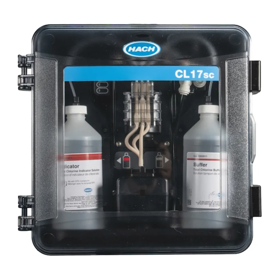
The CL17sc analyzer measures the concentration of free or total chlorine in water in the range of 0.03 to 10 mg/L at 150 second intervals. Figure 1 gives an overview of the analyzer.

Figure 1 CL17sc
- Indicator bottle
- Measurement cycle lights (Table 4)
- Pump clamp
- Tubing clip
- Analyzer status light (Table 5)
- Flow meter
- Buffer bottle
- Colorimetric cell
Connect the analyzer to an SC Controller for power, operation, data collection, data transmission and diagnostics. Refer to the SC Controller manual for an overview of the controller.
Note: More than one analyzer can be connected to an SC Controller if the controller has more than one digital SC input connector.
Flow meter
The analyzer has a flow meter that measures the sample flow through the analyzer. Refer to Figure 1.
Sample flows through the analyzer only when the analyzer flushes the cell, which occurs only when measurement cycle light 1 is on. Refer to Table 4. At other times, there is no sample flow and the flow rate shown is zero. To see the flow rate on the display:
- SC4500 Controller—Swipe left or right.
- SC200 and SC1000 Controllers—Push the RIGHT arrow on the controller.
Measurement cycle lights
The measurement cycle lights show the step of the measurement cycle being done. Refer to Table 4.
Table 4 Measurement cycle lights
| Lights on |  |  |  |
| Description | The cell is flushed with water. | The buffer solution and the indicator solution are added to the cell. | The sample is measured. |
Analyzer status light
The analyzer status light changes from green to yellow when there is a warning (the analyzer continues to operate). The analyzer status light changes to red when there is an error (all operations stop). Refer to Table 5.
Table 5 Analyzer status light
| Color | Description |
| Green | Normal operation |
| Yellow | The system needs attention to prevent a failure in the future. Measurements continue. To show the warnings:
Refer to Warnings—Yellow light. |
| Red | The system needs immediate attention. Measurements have stopped. To show the errors:
Refer to Errors—Red light. |
Product components
Make sure that all components have been received. Refer to Figure 2. If any items are missing or damaged, contact the manufacturer or a sales representative immediately.

Figure 2 Product components
- CL17sc analyzer
- Installation kit
- Tubing Kit (tubing harness and stir bar)
Installation
Multiple hazards. Only qualified personnel must conduct the tasks described in this section of the document.
Installation guidelines
- The analyzer is supplied with a standpipe installation kit or a pressure regulator installation kit(selected at the time of purchase) to control the inlet water pressure. Measure the inlet water pressure in the sample line that connects to the Y-strainer assembly. Refer to Figure 3, Figure 4 or Figure 5.
- Install the analyzer indoors in an environment with minimum vibration. Refer to the operating temperature and humidity specifications in Specifications.
- Do not install the analyzer in direct sunlight because bright light interferes with the colorimetric measurement. Do not install the analyzer near a heat source because heat can cause the reagents to degrade.
- For standpipe installations, install the analyzer in a location with sufficient free space above the analyzer for the standpipe mounting.
- Install the analyzer near an open drain. Refer to the local regulatory agency for disposal instructions.
Sample requirements
NOTICE
The Y-strainer is a sufficient filter for finished drinking water applications. Other applications may require additional filtration for correct instrument operation, e.g., a coarse filter before the Y-strainer or a fine filter after the Y‑strainer.
The water from the sample source(s) must agree with the specifications in Table 2.
Keep the sample flow rate and operating temperature as constant as possible for best performance. A flow rate of 160 (± 40) mL/minute is recommended for best performance.
Sample line guidelines
Select a good, representative sampling point for the best instrument performance. The sample must be representative of the entire system.
To prevent erratic readings:
- Collect samples from locations that are sufficiently distant from points of chemical additions to the process stream.
- Make sure that the samples are sufficiently mixed.
- Make sure that all chemical reactions are complete.
- Install the analyzer as near the sample source as possible (4.6 m (15 ft) maximum).
Drain line guidelines
NOTICE
Incorrect installation of the external air break or drain lines can cause liquid to go back into the instrument and cause damage.
- Make sure to install the external air break, which decreases condensation and possible corrosion inside the analyzer. Refer to Figure 3, Figure 4 or Figure 5.
- Make the drain lines as short as possible.
- Make sure that the drain lines have a constant slope down.
- Make sure that the drain lines do not have sharp bends and are not pinched.
- Make sure that the drain lines are not submerged in water. Air in the drain line is necessary for correct flow.
Air purge (optional)
Air purge may be necessary if the analyzer is installed in a location with high humidity and/or fumes that cause corrosion. The air purge keeps positive pressure in the instrument with dry and clean air.
Supply clean, dry instrument-quality air at 0.003 m3/minute (0.1 ft3/minute) at 20 psig maximum.
Refer to the illustrated steps that follow. The 3/8-inch quick-connect fitting and tubing is supplied by the user.

Mount and plumb the analyzer
Instrument performance is dependent on the correct installation and plumbing of the analyzer and related components. Follow each installation step carefully.
- Select a sampling point location in the process stream that will pull a good, representative sample for the analyzer. The water from the sample source must agree with the requirements in Table 2. To prevent erratic readings:
- Make sure that the sample is collected far from locations where treatment chemicals are added to the process water.
- Make sure that the sample stream is sufficiently mixed and that all chemical reactions are complete before the sample is collected.
- Select a location near the sampling point for the analyzer installation. Make sure that the tubing length from the sampling point to the analyzer inlet is not more than 4.6 m (15 ft).
- Attach the analyzer to a wall with four screws. Make sure that the analyzer is level.
![warning]() Note: The user supplies the mounting hardware.
Note: The user supplies the mounting hardware. - Attach the SC Controller to a wall, panel or pipe. Refer to the SC Controller documentation for instructions.
- Assemble the Y-strainer. Refer to the instructions on the packing list.
- Use the 1-inch conduit clamp to mount the Y-strainer assembly. Make sure that the angled bypass port points down. Make sure that the flow arrow on the Y-strainer points in the direction of the sample flow towards the analyzer inlet.
- Install the external air break on the analyzer. Refer to the instructions on the packing list.
- Plumb the sample drain tubing to an open drain. Refer to Drain line guidelines.
- Plumb the sample to the analyzer. Refer to the applicable section that follows:
- Installation with a standpipe—4.5–10 psi at Y-strainer inlet
- Installation with a standpipe—10–75 psi at Y-strainer inlet
- Installation with a pressure regulator
Installation with a standpipe—4.5–10 psi at Y-strainer inlet
Refer to Figure 3 and the steps that follow to plumb the sample to the analyzer with a standpipe for sample pressures of 31 to 69 kPa (4.5 to 10 psi). Measure the sample pressure at the Y-strainer inlet.
- Assemble the standpipe. Refer to the instructions on the packing list.
- Use the smaller conduit clamp to mount the standpipe assembly above the top of the analyzer. Make sure that the top of the standpipe is a minimum of 61 cm (24 in.) above the top of the analyzer.
- Install one end of the black sample bypass tubing to the bypass port of the Y-strainer. Push the other end of the tubing behind the conduit clamp and then into the standpipe. Put 10–13 cm (4–5 in.) of the tubing in the top of the standpipe.
- Assemble the grab sample assembly.
- Install a piece of the black sample tubing to the Y-strainer outlet. Install the other end of the tubing to the tee fitting of the grab sample assembly.
- Install a piece of the black sample tubing to the inlet port of the analyzer. Install the other end of the tubing to the tee fitting of the grab sample assembly.
- Cut a length of the sample drain tubing to plumb the bottom of the standpipe to an open drain. Refer to Drain line guidelines.
- Use the black tubing to connect the shut-off valve (in the closed position) on the Y-strainer inlet to the sample source. Keep the shut-off valve on the Y-strainer inlet closed for now to prevent flooding.
- Go to Install the stir bar and tubing harness.

Figure 3 Installation with a standpipe (4.5–10 psi at Y-strainer inlet)
- Sample inlet fitting
- External air break
- Sample drain tubing
- Grab sample assembly
- Y-strainer assembly
- Shut-off valve at Y-strainer inlet
- SC Controller
- Sample bypass tubing
- Analyzer
- Standpipe
- Standpipe drain tubing
Installation with a standpipe—10–75 psi at Y-strainer inlet
Refer to Figure 4 and the steps that follow to plumb the sample to the analyzer with a standpipe for sample pressures of 69 to 517 kPa (10 to 75 psi). Measure the sample pressure at the Y-strainer inlet.
- Assemble the standpipe. Refer to the instructions on the packing list.
- Use the smaller conduit clamp to mount the standpipe assembly above the top of the analyzer. Make sure that the top of the standpipe is a minimum of 91 cm (36 in.) above the top of the analyzer.
- Assemble the grab sample assembly.
- Install a piece of the black sample tubing to the standpipe fitting on the side near the bottom of the standpipe. Install the other end of the tubing to the tee fitting of the grab sample assembly.
- Install a piece of the black sample tubing to the inlet port of the analyzer. Install the other end of the tubing to the tee fitting of the grab sample assembly.
- Install a piece of the black sample tubing from the Y-strainer outlet to the bottom of the standpipe.
- Cut a length of the sample drain tubing to plumb the drain port at the top of the standpipe to an open drain. Refer to Drain line guidelines.
- Use the black tubing to connect the shut-off valve (in the closed position) on the Y-strainer inlet to the sample source. Keep the sample valve closed for now to prevent flooding.
- Go to Install the stir bar and tubing harness.

Figure 4 Installation with a standpipe (10–75 psi at Y-strainer inlet)
- Sample inlet fitting
- External air break
- Sample drain tubing
- Grab sample assembly
- Y-strainer assembly
- Shut-off valve at Y-strainer inlet
- SC Controller
- Inlet of the standpipe
- Analyzer
- Standpipe
- Standpipe drain tubing
Installation with a pressure regulator
Refer to Figure 5 and the steps that follow to plumb the sample to the analyzer with a pressure regulator.
- With the black tubing, connect the outlet port of the Y-strainer to the inlet port of the pressure regulator.
![warning]() Note: Make sure that the flow arrow on the regulator points in the direction of the sample flow towards the analyzer inlet.
Note: Make sure that the flow arrow on the regulator points in the direction of the sample flow towards the analyzer inlet. - Assemble the grab sample assembly.
- Install a piece of the black sample tubing to the outlet port of the pressure regulator. Install the other end of the tubing to the tee fitting of the grab sample assembly.
- Install a piece of the black sample tubing to the inlet port of the analyzer. Install the other end of the tubing to the tee fitting of the grab sample assembly.
- With the black tubing, connect the shut-off valve on the Y-strainer bypass port to an open drain.
![warning]() Note: The shut-off valve on the bypass port of the Y-strainer must be kept partially open for the pressure regulator to operate correctly and to prevent leaks within the analyzer cabinet. At minimum, keep a trickle of water flowing through the bypass tubing at all times when the analyzer operates.
Note: The shut-off valve on the bypass port of the Y-strainer must be kept partially open for the pressure regulator to operate correctly and to prevent leaks within the analyzer cabinet. At minimum, keep a trickle of water flowing through the bypass tubing at all times when the analyzer operates. - Use the black tubing to connect the shut-off valve (in the closed position) on the Y-strainer inlet to the sample source. Keep the sample valve closed for now to prevent flooding.

Figure 5 Installation with a pressure regulator
- Sample inlet fitting
- External air break
- Sample drain tubing
- Grab sample assembly
- Y-strainer assembly
- Shut-off valve at the Y-strainer bypass
- SC Controller
- Sample bypass tubing
- Analyzer
- Pressure regulator
Install the stir bar and tubing harness
Do the illustrated steps that follow.

Install the reagent bottles
Chemical exposure hazard. Obey laboratory safety procedures and wear all of the personal protective equipment appropriate to the chemicals that are handled. Refer to the current safety data sheets (MSDS/SDS) for safety protocols.
Items to collect:
- Personal protective equipment (refer to MSDS/SDS)
- Indicator bottle
- Buffer bottle
- DPD compound bottle
- Put on the personal protective equipment identified in the safety data sheets (MSDS/SDS).
- Install the buffer bottle on the right side and the indicator bottle on the left side. Refer to the illustrated steps that follow.
![warning]() Note: (Optional) Use the top of the analyzer as a shelf.
Note: (Optional) Use the top of the analyzer as a shelf.


Set the sample flow to on
- Close the shut-off valve at the Y-strainer inlet. Slowly open the upstream valve that supplies the sample water to the Y-strainer inlet.
- Make sure that there are no leaks at the plumbing connections. If there is a leak, push the tube farther into the fitting or tighten the connection with a wrench.
- For standpipe installations 10 psi or less, refer to Figure 3 in Mount and plumb the analyzer and do the steps that follow:
- Fully open the shut-off valve at the Y-strainer outlet.
- Slowly open the shut-off valve at the Y-strainer inlet until a small stream of water comes out of the standpipe drain tubing.
- For standpipe installations 10 psi or more, refer to Figure 4 in Installation with a standpipe—10–75 psi at Y-strainer inlet and do the steps that follow:
- Fully open the shut-off valve at the Y-strainer outlet.
- Slowly open the shut-off valve at the Y-strainer inlet.
- Adjust the flow until water flows out of the standpipe drain tubing but does not flow out the top of the standpipe.
- For pressure regulator installations, refer to Figure 5 in Installation with a pressure regulator and do the steps that follow:
- Fully open the shut-off valves at the Y-strainer inlet and outlet.
- Slowly open the shut-off valve at the Y-strainer bypass until a small stream of water comes out of the Y-strainer bypass tubing. Refer to Figure 5 in Installation with a pressure regulator.
- Adjust the pressure regulator until 10 to 34 kPa (1.5 to 5 psi) or 200–500 mL/min is measured at the analyzer inlet. Do not fully open the regulator.
Note: Use the pressure regulator to control the sample flow, not the shut-off valves.
Note: The quantity of fluid that flows through the bypass tubing changes the sample pressure and flow that goes to the analyzer.
Electrical installation
Connect the analyzer to the controller

Electrical shock hazard. Externally connected equipment must have an applicable country safety standard assessment.
Connect the analyzer cable to a digital SC input connector of the SC Controller. Refer to Figure 6.

Figure 6 Connect the cable to the digital SC input connector
Keep the connector cap to seal the connector opening in case the cable must be removed.
Note: Extension cables are available. Refer to Replacement parts and accessories. The maximum cable length is 15 m (49 ft).
Connect the controller to power
Connect the controller to line power by hard-wiring in conduit or wiring to a power cord. Refer to the controller documentation for instructions.
Connect external devices to the controller
Connect the controller relays, analog outputs, digital inputs or digital outputs to external devices as necessary. Refer to the controller documentation for instructions.
Set up and prime the analyzer
Prime the analyzer to fill the tubing with reagents and to remove air from the tubing.
- Start the prime process as follows:
- SC4500 Controller—Select the tile of the device, then select Device menu > Prime reagents > OK.
- SC200 and SC1000 Controllers—Go to the main menu, then select SENSOR SETUP > [select analyzer] > PRIME.
- Push menu, then select TEST/MAINT > SCAN DEVICES.
- When the sensor is found and installed, prime the analyzer again.
![warning]() Note: If the SC200 controller does not recognize the analyzer is connected, do the steps that follow:
Note: If the SC200 controller does not recognize the analyzer is connected, do the steps that follow:
- Wait for the prime sequence to finish. Make sure there are no leaks in the system.
Set the flow rate
The analyzer has a flow meter that measures the sample flow through the analyzer. Refer to Figure 1 in "Product overview". If possible, set the flow rate to 120 mL/min or more for the best analyzer performance.
- Swipe left or right, or push the RIGHT arrow to show the flow rate on the display.
Sample flows through the analyzer only when the measurement cycle light 1 is on. When the other measurement cycle lights are on, there is no sample flow and the flow rate shown is zero. Refer to Table 4 for descriptions of the measurement cycle steps.
![warning]() Note: To manually measure the flow rate through the analyzer, measure the flow rate at the analyzer drain when the analyzer flushes the cell with water.
Note: To manually measure the flow rate through the analyzer, measure the flow rate at the analyzer drain when the analyzer flushes the cell with water. - For standpipe installations, adjust the shut-off valve at the Y-strainer inlet to set the flow rate between 60 and 200 mL/min when the analyzer flushes the cell with water.
- For pressure regulator installations, adjust the pressure regulator to set the flow rate between 60 and 200 mL/min when the analyzer flushes the cell with water.
Install the latest software
Make sure that the SC Controller has the latest software installed. Use an SD card (SC200 and SC1000 Controllers) or a USB drive (SC4500 Controller) to install the latest software on the SC Controller.
- Go to the product page for the applicable SC Controller on http://hach.com.
- Click the "Resources" tab.
- Scroll down to "Software/Firmware".
- Click the link for the SC Controller software.
- Save the files to an SD card (SC200 and SC1000 Controllers) or a USB drive (SC4500 Controller).
- Install the files on the SC Controller. Refer to the software installation instructions supplied with the software files.
Configuration
Configure the analyzer
Set the analyzer name, signal average, type of chlorine measured, bubble reject and chlorine alarm setpoints.
- Go to the configuration menu:
- SC4500 Controller—Select the tile of the device, then select Device menu > Settings.
- SC200 and SC1000 Controllers—Go to the main menu, then select SENSOR SETUP > [select analyzer] > CONFIGURE.
- Select an option.
| Option | Description |
| Edit name (or EDIT NAME) | Sets the name of the analyzer. The name of the analyzer shows on the controller display and in the log files. |
| Signal average (or SIGNAL AVERAGE) | Sets the number of measurements used to calculate the average measurement shown on the display. Options: 1 (default), 2, 3, Irregular value (or IRREGULAR VALUE). When the signal average option is set to 1, signal averaging is disabled. When the signal average option is set to 2 or 3, an average reading shows on the display. For example, the measurement on the display is equal to the last and previous measurement divided by two when the signal average option is set to 2. When the signal average option is set to Irregular value (or IRREGULAR VALUE), the analyzer rejects a reading that is unusually higher or lower than the previous several readings. When a reading is rejected, the last good reading stays on the display and is saved to the data log. No more than three consecutive readings can be rejected before the new reading is shown and logged. The signal averaging function corrects for erratic fluctuations in the readings that can occur when bubbles and/or larger particles are in the sample. |
| Measurement type settings (or MEASUREMENT) | Sets the type of chlorine measured. Options: Free Chlorine (or FREE CHLORINE) (default) or Total Chlorine (or TOTAL CHLORINE). If the buffer and indicator bottles have "Free Chlorine" on their labels, select the Free Chlorine option. If the buffer and indicator bottles have "Total Chlorine" on their labels, select the Total Chlorine option. |
| Bubble reject (or BUBBLE REJECT) | Sets the bubble reject option to Yes (YES) or No (NO) (default). Set the Bubble reject option to Yes (YES) to decrease noise caused by bubbles in the sample. Air bubbles in the sample can cause the readings to not be stable. |
| High chlorine alarm limit (or HIGH CL ALARM) | Sets the chlorine concentration that triggers an alarm for high chlorine— 0.00 to 10.00 mg/L (default: 4.00 mg/L). |
| Low chlorine alarm limit (or LOW CL ALARM) | Sets the chlorine concentration that triggers an alarm for low chlorine—0.00 to 10.00 mg/L (default: 0.20 mg/L). |
| Sensor information (or SENSOR INFO) | Shows the analyzer serial number, software version, boot version and driver version. |
| Reset (or DEFAULT SETTINGS) | Select Yes (YES) to change the configuration settings back to the factory default values. |
| Service (or SERVICE) | For service use only |
System configuration
Refer to the controller documentation for system configuration, general controller settings and setup for outputs and communications.
User navigation
Refer to the controller documentation for keypad description and navigation information.
On the SC200 Controller or SC1000 Controller, push the RIGHT arrow key multiple times to show more information on the home screen and to show a graphical display.
On the SC4500 Controller, swipe on the main screen to the left or right to show more information on the home screen and to show a graphical display.
Operation
Data, event and service logs
The controller provides access to a data log, event log and service log for each connected instrument. The analyzer measurements are saved automatically to the data log at 150 second intervals. The event log shows the events that have occurred. The event and data logs keep approximately 2 weeks of data when the analyzer operates continuously. The service log keeps approximately 24 hours of data when the analyzer operates continuously.
Refer to the controller documentation to download the data log, event log and/or service log. The data log is an XML file (SC200 and SC1000 Controllers) that can be saved in CSV or Excel format. The event log and service log are files in CSV format. All SC4500 Controller log files are in CSV format.
Measure a grab sample
When necessary, use the grab sample option to add a water sample or chlorine standard solution to the cell for measurement. Use the grab sample option for verification of the analyzer performance or to measure a water sample collected from another location.
- Go to the grab sample menu:
- SC4500 Controller—Select the tile of the device, then select Device menu > Grab sample.
- SC200 and SC1000 Controllers—Go to the main menu, then select SENSOR SETUP > [select analyzer] > GRAB SAMPLE IN.
- Complete the steps that show on the display. When prompted, remove the cell lid and add a minimum of 100 mL of the grab sample to the cell. Some of the sample will flow to the sample drain.
Modbus registers
A list of Modbus registers is available for network communication. Refer to the manufacturer's website for more information.
Calibration and adjustment
The calibration curve of the analyzer is set at the factory for performance to specifications.
No user adjustments to the factory calibration curve are recommended unless required by a regulatory agency for compliance reporting purposes, or a large repair of the analyzer is done.
For information on verification of the analyzer performance, refer to the instructions in the Calibration Verification Kit (refer to Replacement parts and accessories) or contact technical support.
Maintenance
Multiple hazards. Only qualified personnel must conduct the tasks described in this section of the document.
NOTICE
Do not disassemble the instrument for maintenance. If the internal components must be cleaned or repaired, contact the manufacturer.
Maintenance schedule
Table 6 shows the recommended schedule of maintenance tasks. Facility requirements and operating conditions may increase the frequency of some tasks.
Table 6 Maintenance schedule
| Task | 1 month | 6 months | As necessary |
| Clean the cell | X[2] | ||
| Replace the reagent bottles | X | ||
| Clean the screen in the Y-strainer | X | ||
| Replace the stir bar and tubing harness[3] | X | ||
| Clean the flow meter[4] | X |
Clean the cell
Chemical exposure hazard. Obey laboratory safety procedures and wear all of the personal protective equipment appropriate to the chemicals that are handled. Refer to the current safety data sheets (MSDS/SDS) for safety protocols.
Clean the cell at 1-month intervals or more frequently if necessary.
Items to collect:

2 Clean the cell more or less frequently as necessary.
3 Refer to the instructions supplied with the Tubing Kit.
4 Clean the flow meter for applications that develop biofilm or sediment fouling. Refer to the cleaning instructions DOC273.53.80686.
5 Refer to Replacement parts and accessories.
6 Do not use other cleaning solutions. Refer to Replacement parts and accessories.
- Put on the personal protective equipment identified in the safety data sheets (MSDS/SDS).
- Go to the cell cleaning menu:
- SC4500 Controller—Select the tile of the device, then select Device menu > Standard tasks > Cell cleaning.
- SC200 and SC1000 Controllers—Go to the main menu, then select SENSOR SETUP > [select analyzer] > TASKS > CLEAN CELL.
![warning]() Note: To stop a selected task, push home.
Note: To stop a selected task, push home.
- Push OK (or enter) to stop measurements.
- Select an option.
| Option | Description |
| Hold last measurement value (or HOLD) | The controller outputs are held at the last measured value. |
| Transfer measurement value (or TRANSFER) | The controller outputs change to the transfer value. |
- When the status light flashes, do the illustrated steps that follow. When done, push OK (or enter).
At illustrated step 5, make sure that there is no unwanted material in the cell. Use a flashlight to look for unwanted material as necessary.

- When "Task was successfully completed." (or "TASK COMPLETE") shows on the display, push OK (or enter).

The analyzer starts a measurement cycle in approximately 30 seconds.
Replace the reagent bottles
Chemical exposure hazard. Obey laboratory safety procedures and wear all of the personal protective equipment appropriate to the chemicals that are handled. Refer to the current safety data sheets (MSDS/SDS) for safety protocols.
Chemical exposure hazard. Dispose of chemicals and wastes in accordance with local, regional and national regulations.
Replace the reagents bottles at 1-month intervals.
- Put on the personal protective equipment identified in the safety data sheets (MSDS/SDS).
- Go to the replace reagents menu:
- SC4500 Controller—Select the tile of the device, then select Device menu > Standard tasks > Replace reagents.
- SC200 and SC1000 Controllers—Go to the main menu, then select SENSOR SETUP > [select analyzer] > TASKS > CHANGE REAGENTS.
![warning]() Note: To stop a selected task, push home.
Note: To stop a selected task, push home.
- Push OK (or enter) to stop measurements.
- Select an option.
| Option | Description |
| Hold last measurement value (or HOLD) | The controller outputs are held at the last measured value. |
| Transfer measurement value (or TRANSFER) | The controller outputs change to the transfer value. |
- Wait for the status light to flash.
- Replace the buffer bottle as follows:
![warning]() Note: (Optional) Use the top of the analyzer as a shelf.
Note: (Optional) Use the top of the analyzer as a shelf. - Remove the cap and seal from the new buffer bottle.
- Remove the used buffer bottle from the analyzer.
- Put the buffer tubing in the new buffer bottle on the right side of the analyzer. Tighten the cap.
- Replace the indicator bottle as follows:
- Remove the cap and seal from the indicator bottle and the brown DPD bottle.
- Fill the brown DPD bottle approximately ¼ full with indicator solution.
- Swirl the DPD bottle to mix.
- Put the contents of the DPD bottle into the indicator bottle.
- Invert the indicator bottle until all of the powder is dissolved (2 minutes).
- Remove the used indicator bottle from the analyzer.
- Put the indicator tubing in the new indicator bottle on the left side of the analyzer. Tighten the cap.
- Push OK (or enter).
- When "Task was successfully completed." (or "TASK COMPLETE") shows on the display, push OK (or enter). The analyzer starts a measurement cycle in approximately 30 seconds.
Clean the screen in the Y-strainer
Clean the screen in the Y-strainer when there is a blockage, which is identified with a warning for low sample flow. Complete the illustrated steps that follow.

Prepare for storage
Chemical exposure hazard. Obey laboratory safety procedures and wear all of the personal protective equipment appropriate to the chemicals that are handled. Refer to the current safety data sheets (MSDS/SDS) for safety protocols.
If power to the analyzer will be removed for more than 3 days or the analyzer will not be used for more than 3 days, prepare the analyzer for storage.
Items to collect:

- Remove the reagents from the reagent lines as follows:
- Remove the indicator bottle and buffer bottle from the analyzer.
- Put two beakers (or containers) that contain deionized water in the analyzer.
- Put the indicator bottle tubing and the buffer bottle tubing in the beakers.
- Start the prime sequence as follows:
- SC4500 Controller—Select the tile of the device, then select Device menu > Prime reagents > OK.
- SC200 and SC1000 Controllers—Go to the main menu, then select SENSOR SETUP > [select analyzer] > PRIME. The analyzer removes the reagents from the reagent lines.
- Remove the deionized water from the reagent lines as follows:
- Remove the indicator bottle tubing and the buffer bottle tubing from the beakers.
- Remove the two beakers from the analyzer.
- Start the prime sequence again. The analyzer removes all of the liquid from the reagent lines.
- Disconnect the analyzer cable from the controller (or remove power to the controller).
- Turn the shut-off valve to the closed position to stop sample flow to the Y-strainer.
- Remove the pump clamp. Refer to Figure 7. Keep the pump clamp for later use.
- Remove the water from the cell as follows:
- Remove the lid from the cell.
- Remove the water from the cell with a disposable dropper or a no-lint cloth.
- Install the lid on the cell.
- To start the analyzer after storage, do the steps that follow:
- Install the pump clamp. Refer to Figure 7.

Figure 7 Remove the pump clamp - Install reagent bottles. Refer to Install the reagent bottles.
- Set the shut-off valve to open to start sample flow to the Y-strainer.
- Connect the analyzer cable to the controller, if the cable was disconnected.
- Supply power to the controller, if power was removed.
- Start the prime sequence again.
- Install the pump clamp. Refer to Figure 7.

Prepare for shipping
Chemical exposure hazard. Obey laboratory safety procedures and wear all of the personal protective equipment appropriate to the chemicals that are handled. Refer to the current safety data sheets (MSDS/SDS) for safety protocols.
To prepare the analyzer for shipping, do the steps that follow.
Items to collect:

- Remove the reagents from the reagent lines as follows:
- Remove the indicator bottle and buffer bottle from the analyzer.
- Put two beakers (or containers) that contain deionized water in the analyzer.
- Put the indicator bottle tubing and the buffer bottle tubing in the beakers.
- Start the prime sequence as follows:
- SC4500 Controller—Select the tile of the device, then select Device menu > Prime reagents > OK.
- SC200 and SC1000 Controllers—Go to the main menu, then select SENSOR SETUP > [select analyzer] > PRIME.
The analyzer removes the reagents from the reagent lines.
- Remove the deionized water from the reagent lines as follows:
- Remove the indicator bottle tubing and the buffer bottle tubing from the beakers.
- Remove the two beakers from the analyzer.
- Start the prime sequence again.
The analyzer removes all of the liquid from the reagent lines.
- Disconnect the analyzer cable from the controller.
- Turn the shut-off valve to the closed position to stop sample flow to the Y-strainer.
- Disconnect the sample inlet (black) tubing and drain (clear) tubing from the analyzer.
- Remove the external air break from the analyzer.
- Remove the pump clamp. Refer to Figure 7 in Prepare for storage.
- Remove the tubing harness and stir bar from the analyzer. Keep the tubing harness for shipment with the analyzer. Refer to Install the stir bar and tubing harness.
- Install the pump clamp without the tubing harness. Put tape on the tubing clamp to hold the tubing clamp tightly.
- Remove the water from the cell with a disposable dropper or a no-lint cloth.
- Remove the analyzer from the wall.
- Put the analyzer back in the original packaging.
Clean the instrument
NOTICE
Never use cleaning agents such as turpentine, acetone or similar products to clean the instrument including the display and accessories.
Clean the exterior of the instrument with a moist cloth and a mild soap solution.
Clean spills
Chemical exposure hazard. Dispose of chemicals and wastes in accordance with local, regional and national regulations.
- Obey all facility safety protocols for spill control.
- Discard the waste according to applicable regulations.
Troubleshooting
Errors—Red light
When an error occurs, the analyzer status light changes to red. Measurements stop, the measurement screen flashes and all outputs are held as specified in the controller menu. To show the errors:
- SC4500 Controller—Select the red measurement screen or the small red arrow, or go to the main menu and select Notifications > Errors.
- SC200 and SC1000 Controllers—Go to the main menu, then select DIAGNOSTICS > [select analyzer] > ERROR LIST.
A list of possible errors is shown in Table 7.
Table 7 Error messages
| Error | Description | Solution |
| Detector is defective! (or DETECTOR ERROR) | A detector does not operate correctly. | Update the software. Refer to Install the latest software. Make sure that the installation is indoors, with protection from sunlight or bright indoor lighting. If condensation occurs inside the analyzer, add an air purge. Refer to Air purge (optional). Contact technical support. |
| The cell is dirty! (or DIRTY CELL) | The cell is stained or dirty. Biofilm can grow in the cell when the chlorine concentration is very low. | Clean the cell. Refer to Clean the cell. |
| Application code has failed and is unrecoverable. (or APP CODE FAIL) | A software error occurred. | Contact technical support. |
| LED is defective! (or LED ERROR) | The light in the cell does not operate correctly. | Contact technical support. |
| Pump is defective! (or PUMP ERROR) | The pump does not operate correctly. | Contact technical support. |
| Sample valve is leaking! (or SAMPLE LEAK) | There is a sample leak in the analyzer. | Examine the tubing inside the analyzer for leaks. Make sure that the standpipe or regulator is installed with the correct configuration. If there is no sample leak, look for irregular sample pressure in the inlet sample line, e.g., from a diaphragm pump. Use the >10 psi standpipe installation kit if the inlet sample has irregular pressure. Refer to Figure 3 in Mount and plumb the analyzer, Figure 4 in Installation with a standpipe—10–75 psi at Y-strainer inlet or Figure 5 in Installation with a pressure regulator. Contact technical support. |
| English only (or ENGLISH ONLY) | Some of the analyzer software is damaged. | Update the software. Refer to Install the latest software. |
Warnings—Yellow light
When a warning occurs, the status indicator light changes to yellow. A warning icon flashes and a message is shown on the bottom of the controller display. If sufficient sample flow is available, a warning does not affect the operation of menus. A warning does not affect the operation of the relays and outputs. To show the warnings:
- SC4500 Controller—Select the yellow measurement screen or the small yellow arrow, or go to themain menu and select Notifications > Warnings.
- SC200 and SC1000 Controllers—Go to the main menu, then select DIAGNOSTICS > [select analyzer] > WARNING LIST.
A list of possible warnings is shown in Table 8.
Table 8 Warning messages
| Warning | Description | Solution |
| Bubbles detected. (or BUBBLES DETECTED) | There are bubbles in the cell. | Clean the cell. Refer to Clean the cell. (Optional) Use the bubble reject setting to decrease the signal noise caused by bubbles in the sample. Refer to Configure the analyzer. |
| Cell cleaning is recommended. (or CLEAN CELL SOON) | The cell is getting stained or dirty and should be cleaned soon to prevent an error. | Clean the cell. Refer to Clean the cell. |
| Chlorine is high. (or HIGH CHLORINE) | The chlorine concentration is at or more than the high chlorine alarm limit. | Increase the high chlorine alarm setting. Refer to Configure the analyzer. Or Decrease the chlorine concentration of the sample supplied to the analyzer. |
| Chlorine is low. (or LOW CHLORINE) | The chlorine concentration is at or less than the low chlorine alarm limit. | Decrease the low chlorine alarm setting. Refer to Configure the analyzer. Or Increase the chlorine concentration of the sample supplied to the analyzer. |
| Sample flow is low. (or LOW SAMPLE FLOW) | The sample flow measured is less than the minimum sample flow rate. Refer to Specifications. | Set the sample flow rate. Refer to Set the flow rate. Clean the filter in the Y-strainer if necessary to remove a blockage. Refer to Clean the screen in the Y-strainer. Clean the flow meter. Refer to the cleaning instructions DOC273.53.80686. Replace the tubing. |
| High sample flow (or HIGH SAMPLE FLOW) | The sample flow measured is more than the maximum sample flow rate. Refer to Specifications. | Set the sample flow rate. Refer to Set the flow rate. |
Replacement parts and accessories
Personal injury hazard. Use of non-approved parts may cause personal injury, damage to the instrument or equipment malfunction. The replacement parts in this section are approved by the manufacturer.
Note: Product and Article numbers may vary for some selling regions. Contact the appropriate distributor or refer to the company website for contact information.
Consumables
| Description | Quantity | Item no. |
| Reagent Set, Free Chlorine, includes: Buffer bottle, indicator bottle and DPD bottle | 1 | 2556900 |
| Reagent Set, Total Chlorine, includes: Buffer bottle, indicator bottle and DPD bottle | 1 | 2557000 |
| Cell cleaning kit, includes: Sulfuric Acid, 5.25 N, 100 mL, dropper bottle and cotton swabs (10x) | 1 | 8573100 |
| Calibration Verification Kit, includes: Syringe, tubing, tube fittings, ampule breaker, deionized water and chlorine standard ampule | 1 | 8568200 |
| Calibration Verification Refill Kit, includes: Deionized water and chlorine standard ampule | 1 | 8573200 |
Replacement parts
| Description | Item no. |
| Tubing Kit, includes: Tubing harness and stir bar | 8560400 |
| Installation kit with standpipe (10 psi or less) | 8560500 |
| Installation kit with standpipe (more than 10 psi) | 8576001 |
| Installation kit with pressure regulator | 8565700 |
Accessories
| Description | Item no. |
| Extension cable for analyzer, 1 m (3.2 ft) | 6122400 |
| Extension cable for analyzer, 7.7 m (25 ft) | 5796000 |
| Extension cable for analyzer, 15 m (50 ft) | 5796100 |
| Tubing adapter, 6 mm OD to 1/4-inch OD | 09184=A=4020 |
Documents / Resources
References

Download manual
Here you can download full pdf version of manual, it may contain additional safety instructions, warranty information, FCC rules, etc.
Advertisement


Need help?
Do you have a question about the CL17sc and is the answer not in the manual?
Questions and answers