Table of Contents
Advertisement
Advertisement
Table of Contents

Related Manuals for Hach CM130


Summary of Contents for Hach CM130
- Page 1 DOC023.53.80540 CM130 11/2018, Edition 5 User Manual...
-
Page 3: Table Of Contents
Table of Contents Specifications ......................3 General information ....................4 Safety information ......................4 Use of hazard information ..................5 Precautionary labels ..................... 5 Certification ........................6 Indications for Use ....................... 6 Product overview ......................7 Remote indicator lights and sounds ..............11 Product components .................... - Page 4 Table of Contents Show the measurement and event history ..............56 Maintenance ....................... 57 Maintenance schedule ....................57 Monthly maintenance ....................58 Periodic maintenance ....................59 Replace the remote indicator battery ................. 60 Install a software update .................... 61 Calibration ........................61 Remove power ......................
-
Page 5: Specifications
Specifications Specifications are subject to change without notice. Table 1 General specifications Specification Details Dimensions Analyzer: 37.0 x 53.8 x 22.6 cm (14.6 x 21.2 x 8.9 in.) (W x H x D) Remote indicator: 12.3 x 29.4 x 10.7 cm (4.8 x 11.6 x 4.2 in.) Enclosure Enclosure rating: IP52 rated with the door closed Enclosure material: PC/ABS case, PC door, PC hinges and latches, 316 SST... -
Page 6: General Information
Table 1 General specifications (continued) Specification Details Lights Analyzer: Two colors (amber and red) show the analyzer status or chlorine status on the display. Remote indicator: Two indicator lights show the analyzer status with three colors (blue, amber or red). Two indicator lights show the chlorine status with two colors (blue or red). -
Page 7: Use Of Hazard Information
Please read this entire manual before unpacking, setting up or operating this equipment. Pay attention to all danger and caution statements. Failure to do so could result in serious injury to the operator or damage to the equipment. Make sure that the protection provided by this equipment is not impaired. Do not use or install this equipment in any manner other than that specified in this manual. -
Page 8: Certification
(i.e. total chloramines plus free chlorine) in feed water used to prepare dialysate in hemodialysis systems. The CM130 is a component of the complete water treatment system for hemodialysis and does not treat or alter the water used in dialysate. The CM130 instrument’s automated monitoring records total chlorine values in feed water at intervals between 5 and 20 minutes. -
Page 9: Product Overview
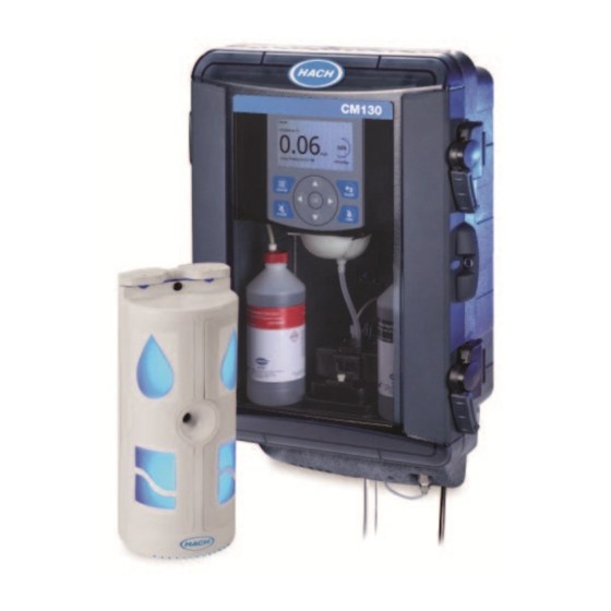
Figure 2 shows an overview of the analyzer interior. The remote indicator for the CM130 identifies the chlorine status and the analyzer status in the treatment room with sound and colored lights. Figure 3 shows an overview of the remote indicator exterior. - Page 10 Figure 1 Analyzer overview—exterior 1 Serial number label 7 Speaker 2 Remote indicator cable fitting 8 Drain fitting 3 Ethernet cable fitting 9 Sample inlet fitting 4 Power cord, 244 cm (8 ft) 10 Colorimeter inlet fitting (metal) 5 Mounting brackets (2x) 11 Case drain outlet 6 Sample conditioning module 8 English...
- Page 11 Figure 2 Analyzer overview—interior 1 Reagent tray 5 Display 9 Magnetic stirrer 2 Indicator bottle cap (red) 6 Reagent delivery module 10 Colorimeter window 3 SD card slot 7 Funnel 11 Colorimeter 4 Keypad 8 Buffer bottle cap (black) 12 Stir motor The colorimeter does not come installed.
- Page 12 Figure 3 Remote indicator overview 1 Speaker 5 Channel for cable 2 Analyzer status lights 6 Alternative cable routing 3 Chlorine status lights 7 Wall mounting holes 4 Ceiling mounting holes 10 English...
-
Page 13: Remote Indicator Lights And Sounds
Remote indicator lights and sounds The analyzer status and the chlorine status are identified with sounds and colored lights on the remote indicator in the treatment room. Refer to Table 3 Table 4. Similar alert and alarm sounds occur at the remote indicator and the analyzer. When the battery life of the remote indicator is low, the remote indicator makes a continuous sound. -
Page 14: Product Components
Figure 4. If any items are missing or damaged, contact the manufacturer or a sales representative immediately. Keep the packaging for later use. Figure 4 Product components 1 CM130 analyzer 5 Thumbscrew 2 Installation kit (refer to Figure 6 Colorimeter... - Page 15 Figure 5 Installation kit 1 Grab sample assembly 4 Beaker, plastic, 100 mL 2 Sample inlet tubing, black, ¼-in. OD, 15 m (50 ft) 5 DVD with installation overview video 3 Drain tubing, clear, ½-in. ID, 3 m (10 ft) Figure 6 Monthly maintenance kit (not included) 1 Indicator bottle 4 Zero standard water...
-
Page 16: Items To Collect
Items to collect Collect the items that follow to install the instrument. The items that follow are supplied by the user. Get the TCP/IP addresses of the analyzer, subnet mask, default gateway and network time protocol (NTP) server(s) from the network administrator to configure the instrument. Refer to Configure the network settings on page 46. -
Page 17: Installation
Installation Look at the installation overview video A video that shows an overview of the installation steps is supplied on the DVD in the installation kit. Note: The video does not show all of the installation steps. Make sure to refer to this manual for all of the installation steps. - Page 18 Figure 9 Analyzer dimensions 16 English...
-
Page 19: Complete The Equipment Installation Qualification Document
Complete the equipment installation qualification document Use the supplied equipment installation qualification document to record that the analyzer and remote indicator are correctly installed. Refer to Figure 1. As each installation step in this manual is completed, record that the step is done in the applicable section of the supplied equipment installation qualification document. -
Page 20: Analyzer Mounting
Analyzer mounting N O T I C E For accurate readings, the analyzer must be horizontal within ±10 mm (0.39 in.) and vertical within ±10 mm (0.39 in.). Attach the analyzer to a wall. The fasteners are supplied by the user. Note: An illustration is supplied for each step number. - Page 21 2. Hang the analyzer and make it vertical as follows: a. Hang the analyzer mounting brackets on the fasteners. Push the analyzer against the wall. b. Put the level behind the door latches on the surface that is parallel to the wall. Make sure that the analyzer is vertical within ±10 mm (0.39 in.).
-
Page 22: Plumb The Analyzer
C A U T I O N Personal/Patient injury hazard. Only the tubing supplied by Hach Company may be used with the instrument. Other tubing may absorb chlorine that is in the sample water and have a negative effect on chlorine readings (decrease the chlorine readings). - Page 23 Items supplied with the analyzer: Shown in Figure Figure 11 Plumbing parts 1 Grab sample assembly 4 Sample inlet tubing, black, 15 m (50 ft) 2 Check valve 5 Drain tubing, clear, 3 m (10 ft) 3 Grab sample valve 1.
- Page 24 3. Push the black tubing of the grab sample assembly into the sample inlet fitting. The sample inlet fitting is behind the metal colorimeter inlet fitting. 4. Plumb the sample inlet tubing as follows: a. Plumb one end of the coil of black tubing to the sample source between the primary and secondary carbon tanks, as identified in ANSI/AAMI/ISO 13959 Water for hemodialysis and related therapies.
- Page 25 5. Install a sample filter (Y-strainer) and a shut-off valve as follows: a. Plumb a sample filter in the black tubing between the check valve and the sample source. b. (Optional) If the analyzer is not near the sample source, install a shut-off valve near the analyzer.
- Page 26 7. Turn the sample source valve and the shut-off valve counter-clockwise. Sample is supplied to the analyzer. 8. Make sure that there are no leaks at the tubing connections, the bottom of the analyzer or the sample conditioning module. 9. Keep the sample source valve and the shut-off valve open until maintenance is necessary. 24 English...
-
Page 27: Remote Indicator Installation
Remote indicator installation D A N G E R Electrocution hazard. Always remove power to the instrument before making electrical connections. Install the remote indicator in the treatment room on a wall. Items supplied by the user: Fasteners CAT5 cable CAT5e/CAT6 cable (2x) stripper... - Page 28 Items supplied with the analyzer: Shown in Figure Figure 12 Remote indicator components 1 Cover 5 Ceiling mounting holes 2 Housing 6 Wall mounting holes 3 Green, 8-pin connector 7 Backplate 4 Cable strain relief 8 Blade terminal 26 English...
-
Page 29: Remote Indicator Mounting
Remote indicator mounting N O T I C E In accordance with UL 61010-1, the remote indicator must be installed 1.5 m (4.9 ft) or more from patients in the hemodialysis treatment room. Attach the remote indicator to a wall or ceiling in the treatment room. The fasteners are supplied by the user. - Page 30 3. Disassemble the remote indicator as follows: a. Loosen the captive screw at the top of the remote indicator. Remove the cover. b. Loosen the two captive screws that are on the left and right side of the remote indicator. Remove the housing.
- Page 31 4. Use a drill to make the mounting holes for the backplate. Make the hole diameter applicable to the fasteners used. a. Ceiling mount: Make a two-hole pattern 72.4 mm (2.85 in.) wide with the cable opening in the middle. Put the holes at least 37.4 mm (1.47 in.) in front of the cable opening. b.
- Page 32 5. Insert the cable through the cable opening in the backplate. It is recommended to leave at least 60 cm (2 ft) of extra cable length behind the mounting surface for future changes to the installation. 30 English...
- Page 33 6. Attach the backplate to the wall or ceiling. a. Ceiling mount: Attach the backplate to the ceiling with two fasteners. b. Wall mount: Attach the backplate to the wall with two fasteners. English 31...
- Page 34 7. Put the green 8-pin connector that was removed from the housing into the connector holder in the backplate. Note: The connector holder holds the green 8-pin connector during wiring and makes sure that the correct length of cable is kept in the remote indicator. 32 English...
-
Page 35: Connect The Remote Indicator Cable To The Remote Indicator
Connect the remote indicator cable to the remote indicator Connect the remote indicator cable to the green 8-pin connector. 1. Use the CAT5 cable stripper to remove 38 mm (1.5 in.) of the outer cable shielding. 2. Untwist each pair of wires. Use the wire strippers to remove 7 mm (0.25 in.) of plastic from each pair of twisted wires. - Page 36 4. Connect the wires to the green 8-pin connector in the backplate as follows: a. Put the small flat-bladed screwdriver between the pin 1 orange tabs on the connector. Push and hold to open the contacts for wire insertion. b. Put the applicable colored wire for Terminal 1 in Terminal 1. Refer to Table 5 for the wire color for each terminal.
-
Page 37: Assemble The Remote Indicator
Assemble the remote indicator 1. Install the cable strain relief as follows: a. Put the cable in the vertical channels in the backplate. b. Put the cable strain relief on the backplate. Align the screws with the screw holes. c. Tighten the screws. Gently pull the cable to make sure that the cable is held securely by the cable strain relief. - Page 38 3. Attach the housing to the backplate with the two captive screws. 4. Install the cover as follows: a. Align the four tabs on the bottom of the housing with the vent slots on the bottom of the cover. b. Put the cover over the housing. c.
-
Page 39: Analyzer Electrical Installation
Analyzer electrical installation Connect the remote indicator cable and an energized Ethernet cable to the analyzer. Items supplied by the user: Cross-slotted CAT5 cable Wire screwdriver stripper strippers Flat-bladed Flat-bladed Crimper screwdriver, screwdriver, tool small medium Remove the door (optional) N O T I C E To keep the enclosure environmental rating, make sure to reinstall the door when this procedure is complete. -
Page 40: Analyzer Electrical Connectors
Figure 14 Lower the front panel Analyzer electrical connectors Figure 15 shows the electrical connectors in the analyzer. Figure 15 Analyzer electrical connectors 1 Power cord connector 3 Stir motor connector 2 Ethernet connector (RJ45) 4 Remote indicator connector The stir motor connector is connected at the factory. 38 English... -
Page 41: Put The Remote Indicator Cable Into The Analyzer
Put the remote indicator cable into the analyzer Pre-requisite: Cut the remote indicator cable so that it a sufficient length to install the loose end in the analyzer. Put the remote indicator cable through the cable fitting and into the analyzer. Note: An illustration is supplied for each step number. -
Page 42: Connect The Remote Indicator Cable To The Analyzer
Connect the remote indicator cable to the analyzer Install the female blade terminal on the end of the remote indicator cable. Then, connect the remote indicator cable to the remote indicator connector. 1. Use the CAT5 cable stripper to remove 38 mm (1.5 in.) of the outer cable shielding from the remote indicator cable. - Page 43 4. Connect the remote indicator cable to the remote indicator connector as follows: a. Put the small flat-bladed screwdriver between the pin 1 orange tabs on the connector. Push and hold to open the contacts for wire insertion. b. Put the applicable colored wire for Terminal 1 in Terminal 1. Refer to Table 6 for the wire color for each terminal.
-
Page 44: Complete The Remote Indicator Cable Installation
Complete the remote indicator cable installation 1. Install the female blade terminal on the male blade terminal of the analyzer. 2. Push the remote indicator cable into the two cable clamps on the back of the front panel. 3. Tighten the nut of the cable fitting. 4. -
Page 45: Connect The Ethernet
Connect the Ethernet W A R N I N G Electrical shock hazard. Externally connected equipment must have an applicable country safety standard assessment. Connect an energized Ethernet cable with an RJ45 connector to the analyzer. 1. Remove the nut from the cable fitting for the Ethernet cable. 2. - Page 46 5. Use the flat-bladed screwdriver to push the rubber gasket into the cable fitting. 6. Install the nut on the cable fitting. Do not tighten the nut. 7. Connect the RJ45 connector to the Ethernet connector in the analyzer. 8. Tighten the nut. Gently pull the cable to make sure that the cable is held securely by the cable fitting.
-
Page 47: Lift The Front Panel
Lift the front panel Cable installation is complete. Lift the front panel. Tighten the two screws on the front panel to keep the front panel up. Connect the power cord D A N G E R Electrocution hazard. In potentially wet locations, a Ground Fault Circuit Interrupt (GFCI/GFI) device must be used for connecting the equipment to its main power source. -
Page 48: Configure The Network Settings
3. Select Date. 4. Enter the current date. To erase characters, select and push ok. 5. Select Continue. 6. Select Time. 7. Select am or pm. 8. Enter the current time. To erase characters, select and push ok. 9. Select Continue. Configure the network settings Enter the TCP/IP addresses of the analyzer, subnet mask, default gateway and network time protocol (NTP) server(s). -
Page 49: Install The Colorimeter And Reagents
Install the colorimeter and reagents C A U T I O N Personal injury hazard. Only the reagents supplied by Hach Company may be used in the instrument. C A U T I O N Chemical exposure hazard. Obey laboratory safety procedures and wear all of the personal protective equipment appropriate to the chemicals that are handled. - Page 50 Items supplied with the analyzer: Shown in Figure Figure 18 Colorimeter (Tubing Maintenance Assembly Kit) 1 Colorimeter window 5 Reagent delivery board 2 Magnetic stirrer 6 Colorimeter cable 3 Thumbscrew 7 Colorimeter connector 4 Funnel tube fitting 8 Colorimeter tube 48 English...
- Page 51 Start guided installation 1. Push menu. Select Maintenance>Installation (scroll up). Complete the steps that show on the display. The display screens are shown for reference in Appendix A: Screens—Install the colorimeter on page 74. 2. Wait for the analyzer to shut down. When the display is off, disconnect the power cord from the electrical outlet.
- Page 52 Install the colorimeter and reagents 1. Remove the new colorimeter and thumbscrew from the box. 2. Install the colorimeter as follows: a. Tilt the back of the colorimeter down. Put the colorimeter on the stir motor. Refer to the next figure for the location of the stir motor.
- Page 53 7. Connect the colorimeter cable as follows: a. Align and push the colorimeter connector on the mating connector. b. Lift the cable clamp. c. Push the connector into the cable clamp. 8. Put the reagent delivery connector into the reagent delivery board. Refer to the next figure for the location of the reagent delivery connector.
-
Page 54: Install The Door
Figure 19 Analyzer overview—components 1 Pump clamp 6 Metal fitting 2 Reagent delivery module 7 Hole for the colorimeter tube 3 Reagent delivery connector 8 Stir motor 4 Mating connector for the colorimeter connector 9 Funnel tube 5 Cable clamp for the colorimeter cable Install the door Install the door back on the analyzer door hinges. -
Page 55: User Interface And Navigation
User interface and navigation Keypad description Refer to Figure 20 for the keypad description and navigation information. Figure 20 Keypad description 1 mute: Mutes the sound at the remote indicator. 5 ok: Confirms the selection and continues. Mutes the sound at the analyzer with the exception of the high chlorine alarm. -
Page 56: Display Description
Display description Refer to Figure 21 for the home screen description. The home screen shows the analyzer status (measuring or idle, and notifications). Figure 21 Home screen—measurement mode 1 Date and time of the last measurement 5 Notification message 2 Last measurement 6 Percentage of measurement complete 3 Parameter 7 Menu bar... -
Page 57: Operation
N O T I C E Hach recommends that the analyzer is set to idle mode at the end of each treatment day and set back to measurement mode at the start of each treatment day. This will make sure that the analyzer completes the necessary self-diagnostic tests at the start of each treatment day, such as the performance check of the remote indicator lights and speaker. -
Page 58: Show The Measurement And Event History
• Date and time setting • Contact information for technical support • Date the measurement history and event history were last copied to an SD card • Software version installed • Serial number of the analyzer • MAC address of the analyzer Show the measurement and event history Measurements are saved to the measurement log on the analyzer (maximum of 3000). -
Page 59: Maintenance
Maintenance D A N G E R Multiple hazards. Only qualified personnel must conduct the tasks described in this section of the document. C A U T I O N Personal injury hazard. Changes or modifications to this equipment not performed by the manufacturer or expressly specified in Consumables and replacement parts on page 73 or the service manual are... -
Page 60: Monthly Maintenance
C A U T I O N Personal injury hazard. Only the reagents supplied by Hach Company may be used in the instrument. Reagents must be installed and used in a single, contiguous time period as allowed by the instrument. -
Page 61: Periodic Maintenance
Periodic maintenance C A U T I O N Chemical exposure hazard. Obey laboratory safety procedures and wear all of the personal protective equipment appropriate to the chemicals that are handled. Refer to the current safety data sheets (MSDS/SDS) for safety protocols. C A U T I O N Personal injury hazard. -
Page 62: Replace The Remote Indicator Battery
Replace the remote indicator battery D A N G E R Multiple hazards. Do not operate the remote indicator without a battery. The battery is a safety feature. When the battery life of the remote indicator is low, the remote indicator makes a continuous sound. Replace the battery yearly or when the continuous sound is heard. -
Page 63: Install A Software Update
3. Install a new battery. 4. Install the cover of the remote indicator as follows: a. Align the four tabs on the bottom of the housing with the vent slots on the bottom of the cover. b. Put the cover over the housing. c. -
Page 64: Prepare For Storage
Prepare for storage If power to the analyzer will be removed for more than 3 days or the analyzer will not be used for more than 3 days, prepare the analyzer for storage. Item supplied by the user: Deionized water in two beakers 1. - Page 65 Figure 22 Remove the pump clamp English 63...
-
Page 66: Prepare For Shipping
Prepare for shipping To prepare the analyzer for shipping, do the steps that follow. Items supplied by the user: Deionized water in two Cross-slotted Original beakers screwdriver packaging Flat-bladed screwdriver, medium 1. Remove the reagents from the reagent lines as follows: a. -
Page 67: Clean The Instrument
10. Remove the analyzer from the wall as follows: a. Loosen the fasteners for the analyzer until the heads of the fasteners are 0.6 mm (¼ in.) from the wall. b. Lift the analyzer mounting brackets up and off of the fasteners. 11. - Page 68 Table 10 Remote indicator—Light color descriptions 1 Chlorine status light Off: Chlorine is not being measured Blue: Chlorine is less than 0.10 mg/L as Cl Red: Chlorine is 0.10 mg/L or more as Cl 2 Analyzer status light Off: No communication with analyzer Blue: Normal operation Amber: Non-urgent problem with analyzer Red: Urgent problem with analyzer...
-
Page 69: Alerts And Alarms
Alerts and alarms When an alert or alarm occurs, an amber (alert) or red (alarm) notification message shows at the top of the analyzer display. If more than one alert or alarm occurs, the highest priority alert or alarm shows at the top of the analyzer display. To show all of the active alerts and alarms, push menu and select Notifications. - Page 70 Table 13 Alarms (red Message Description Solution Bubbles There are bubbles or Decrease the sample water temperature if possible. detected! turbidity in the sample. Make sure that the sample water is not turbid. Make sure that a light source is not pointed at the colorimeter (e.g., flashlight).
- Page 71 Table 13 Alarms (red ) (continued) Message Description Solution Insufficient The sample flow rate is Make sure that the sample source valve and the shut-off valve for sample flow too low. the analyzer are open (turned counter-clockwise). Make sure that the sample line is connected to the sample source. Adjust the sample pressure so that it is within the instrument requirements.
- Page 72 Table 13 Alarms (red ) (continued) Message Description Solution Monthly Chlorine carryover from 1. Do monthly maintenance again. maintenance has colorimeter disinfection 2. During the disinfection step, pour 200 mL of RO water through failed! process. the funnel instead of the bleach solution. 3.
- Page 73 Table 13 Alarms (red ) (continued) Message Description Solution Reboot the A software error Push menu, then select Power > shut down. Wait for the analyzer device occurred. to shut down. When the display is off, disconnect the power cord Measurements cannot from the electrical outlet.
-
Page 74: Interferences
Interferences The substances that are shown in Table 15 interfere in the chlorine (Cl ) determination at the given concentrations. Table 16 shows the substances that were tested and do not interfere at or below the levels that are shown. Table 15 Interfering substances Interfering substance Interference level... -
Page 75: Consumables And Replacement Parts
9746800 Performance Check Kit (9746600) and Assy, Tubing Maintenance Kit (9638900) Replacement parts Description Item no. Installation Kit, CM130 (grab sample assembly, sample inlet tubing, drain tubing and 9717200 beaker) Power Cord Replacement Kit 9747600 Reagent Delivery Module Replacement Kit... -
Page 76: Appendix A: Screens-Install The Colorimeter
Appendix A: Screens—Install the colorimeter This appendix shows the analyzer display screens, for reference only. 74 English... - Page 77 English 75...
-
Page 78: Appendix B: Screens-Install Reagents
Appendix B: Screens—Install reagents This appendix shows the analyzer display screens, for reference only. 76 English... - Page 79 English 77...
- Page 80 78 English...
- Page 81 English 79...
- Page 82 80 English...
- Page 83 English 81...
- Page 84 82 English...
- Page 85 English 83...
- Page 86 84 English...
-
Page 87: Appendix C: Screens-Data Export
Appendix C: Screens—Data export This appendix shows the analyzer display screens, for reference only. English 85... - Page 88 86 English...
-
Page 89: Appendix D: Screens-Prime Reagents
Appendix D: Screens—Prime reagents This appendix shows the analyzer display screens, for reference only. English 87... - Page 90 88 English...
-
Page 91: Appendix E: Screens-Flush Colorimeter
Appendix E: Screens—Flush colorimeter This appendix shows the analyzer display screens, for reference only. English 89... - Page 92 90 English...
-
Page 93: Appendix F: Screens-Performance Check
Appendix F: Screens—Performance check This appendix shows the analyzer display screens, for reference only. English 91... - Page 94 92 English...
- Page 95 English 93...
- Page 96 94 English...
-
Page 97: Appendix G: Screens-Monthly Maintenance
Appendix G: Screens—Monthly maintenance This appendix shows the analyzer display screens, for reference only. English 95... - Page 98 96 English...
- Page 99 English 97...
- Page 100 98 English...
- Page 101 English 99...
- Page 102 100 English...
- Page 103 English 101...
- Page 104 102 English...
- Page 105 English 103...
- Page 106 104 English...
- Page 107 English 105...
-
Page 108: Appendix H: Symbols Glossary
Appendix H: Symbols glossary Symbol Symbol Symbol Description Standard/Designation Number Title/Reference applicable) Number (if applicable) Manufacturer/5.1.1 Indicates the medical device AAMI / ANSI / ISO 15223-1:2012, medical manufacture devices - symbols to be used with medical devices labels, labeling, and information to be supplied - part 1: general requirements / 5-91 Date of... - Page 109 Symbol Symbol Symbol Description Standard/Designation Number Title/Reference applicable) Number (if applicable) Caution/5.4.4 Indicates the need for the AAMI / ANSI / ISO 15223-1:2012, medical user to consult the devices - symbols to be used with medical instructions for use for devices labels, labeling, and information to important cautionary be supplied - part 1: general requirements /...
- Page 110 Symbol Symbol Symbol Description Standard/Designation Number Title/Reference applicable) Number (if applicable) Warning; Optical To warn of optical radiation ISO 7010 - Graphical symbols -- Safety radiation / W027 colours and safety signs -- Registered safety signs WEEE Symbol The WEEE symbol, EN50419:200 6 - Marking of electrical and indicating separate electronic equipment in accordance with...
- Page 112 *DOC023.53.80540* HACH COMPANY 100 Dayton Ave, Ames, IA 50010 U.S.A. Tel. (970) 669-3050 (800) 227-4224 (U.S.A. only) Fax (970) 669-2932 orders@hach.com www.hach.com © Hach Company/Hach Lange GmbH, 2016–2018. All rights reserved. Printed in U.S.A.
Need help?
Do you have a question about the CM130 and is the answer not in the manual?
Questions and answers