Hach TU5300 sc, TU5400 sc Manual
- Basic user manual (30 pages) ,
- Basic user manual (266 pages) ,
- Basic user manual (226 pages)
Advertisement
- 1 Specifications
- 2 General information
- 3 Installation
- 4 User navigation
- 5 Operation
- 6 Calibration
- 7 Verification
- 8 Maintenance
- 9 Troubleshooting
- 10 Safety information
- 11 Documents / Resources
Specifications
Specifications are subject to change without notice.
| Specification | Details |
| Measurement method | Nephelometry with scattered light collected at a 90-degree angle to the incident light and 360 degrees around the sample vial |
| Primary compliance method | DIN EN ISO 7027 |
| Enclosure | Material: ASA Luran S 777K / RAL7000, TPE RESIN Elastocon STK40, Thermoplastic Elastomer TPS-SEBS (60 Shore) and stainless steel |
| IP rating | Electronic compartment IP55; process head/Automatic Cleaning Module attached to the instrument and all of the other functional units IP651 |
| Dimensions (W x D x H) | 268 x 249 x 190 mm (10.6 x 9.8 x 7.5 in.) |
| Weight | Instrument with the process head: 2.7 kg (6.0 lb); Instrument with the optional automatic cleaning module: 5.0 kg (11.0 lb) |
| Power requirements | 12 VDC (+2 V, –4 V), 14 VA |
| Protection class | III |
| Pollution degree | 2 |
| Overvoltage category | II |
| Environmental conditions | Indoor use |
| Operating temperature | 0 to 50°C (32 to 122°F) |
| Storage temperature | –40 to 60°C (–40 to 140°F) |
| Humidity | 5 to 95% relative humidity, non-condensing |
| Sensor cable length | TU5x00 sc without Automatic Cleaning Module or flow sensor: 50 m (164 ft); TU5x00 sc with Automatic Cleaning Module: 10 m (33 ft) |
| Laser | Class 1 laser product: Contains a non user-serviceable class 1 laser. |
| Optical light source | 850 nm, maximum 0.55 mW |
| Fittings | Sample inlet and outlet: ¼-in. OD tubing (optional tubing adapter, ¼ in. to 6 mm) |
| Altitude | 2000 m (6562 ft) maximum |
| Tubing requirements | Polyethylene, polyamide or polyurethane tubing. Calibrated ¼ in. OD, +0.03 or –0.1 mm (+0.001 or –0.004 in.) |
| Measurement units | TU5300 sc: NTU, FNU, TE/F, EBC or FTU; TU5400 sc: NTU, mNTU2, FNU, mFNU, TE/F, EBC, FTU or mFTU. |
| Range | 0 to 1000 NTU, FNU, TE/F and FTU; 0 to 250 EBC |
| Method detection limit | 0.0001 FNU at 25°C (77°F) |
| Response time | T90 < 30 seconds at 100 mL/min |
| Signal averaging | TU5300 sc: 30–90 seconds TU5400 sc: 1–90 seconds |
| Accuracy | ± 2% or ± 0.01 FNU (the larger value) from 0 to 40 FNU ± 10% of reading from 40 to 1000 FNU based on Formazin primary standard at 25°C (77°F) |
| Linearity | Better than 1% for 0 to 40 NTU based on Formazin primary standard at 25°C (77°F). |
| Repeatability | TU5300 sc: 0.002 FNU or 1% (the larger value) at 25°C (77°F) ( > 0.025 FNU range); TU5400 sc: 0.0006 FNU or 1% (the larger value) at 25°C (77°F) ( > 0.025 FNU range) |
| Stray light | < 0.01 FNU |
| Resolution | 0.0001 FNU (0.0001 to 0.9999/1.000 to 9.999/10.00 to 99.99/100.0 to 1000 FNU) Default: TU5300 sc: 0.001 FNU and TU5400 sc: 0.0001 FNU |
| Air bubble compensation | Physical, mathematical |
| Sample requirements | Temperature: 2 to 60°C (35.6 to 140°F) Conductivity: 3000 µS/cm maximum at 25°C (77°F) Flow rate3: 100 to 1000 mL/min; optimal flow rate: 200 to 500 mL/min Pressure: 6 bar (87 psi) maximum compared to air, 2 to 40°C (35.6 to 104°F) sample; 3 bar (43.5 psi) maximum compared to air, 40 to 60°C (104 to 140°F) sample |
| Calibration options | StablCal or Formazin: 1-point calibration (20 FNU) for 0 to 40 FNU measurement range, 2-point calibration (20 and 600 FNU) for 0 to 1000 FNU (full) measurement range or 2- to 6-point custom calibration for a measurement range of 0 FNU to the highest calibration point. |
| Verification options | Glass verification rod (solid secondary standard) ≤ 0.1 NTU, StablCal or Formazin |
| Verification (RFID or Link2SC) | Verification of the measurement value by comparison of the process and lab measurements with RFID or Link2SC. |
| Certifications | CE compliant; US FDA accession number: 1420492-xxx. This product complies with IEC/EN 60825-1 and to 21 CFR 1040.10 in accordance with Laser Notice No. 50. Australian RCM. |
| Warranty | 1 year (EU: 2 years) |
1 Water drops, puddles or runlets that will not damage the instrument may be in the inner of the enclosure.
2 1 mNTU = 0.001 NTU
3 For the best results, operate the instrument at a flow rate of 200 mL/min when the maximum particle size is 20 µm. For larger particles (150 µm maximum), the best flow rate is 350 to 500 mL/min.
General information
In no event will the manufacturer be liable for direct, indirect, special, incidental or consequential damages resulting from any defect or omission in this manual. The manufacturer reserves the right to make changes in this manual and the products it describes at any time, without notice or obligation. Revised editions are found on the manufacturer's website.
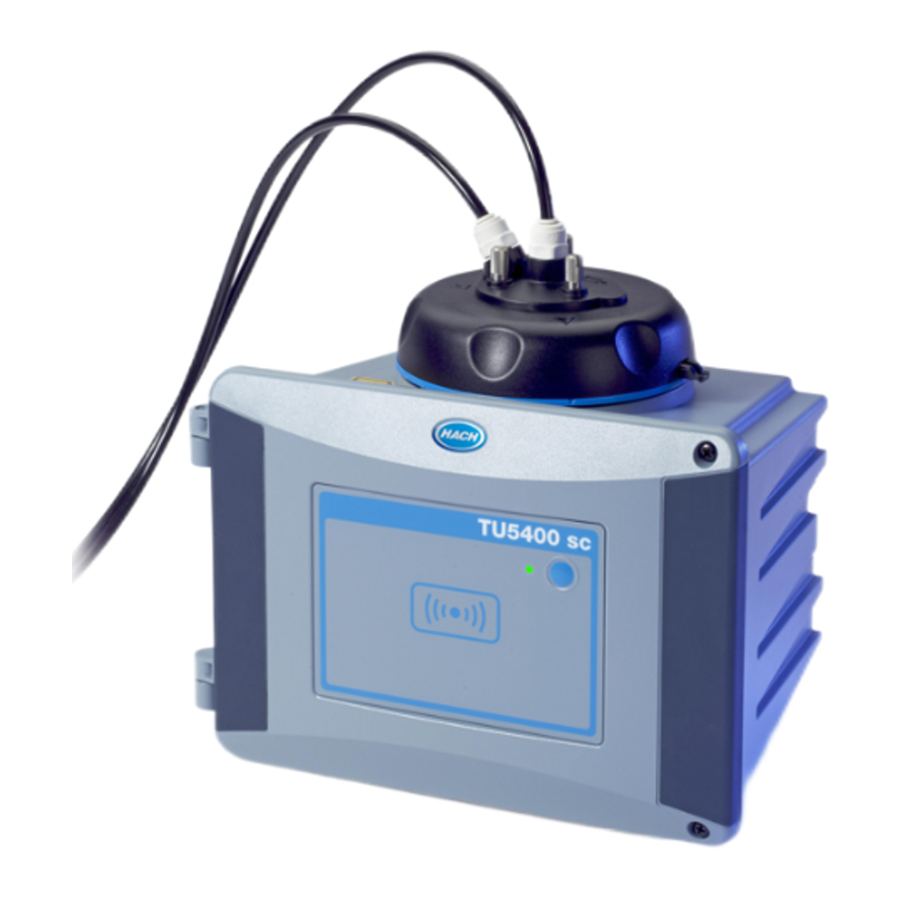
Product overview

Chemical or biological hazards. If this instrument is used to monitor a treatment process and/or chemical feed system for which there are regulatory limits and monitoring requirements related to public health, public safety, food or beverage manufacture or processing, it is the responsibility of the user of this instrument to know and abide by any applicable regulation and to have sufficient and appropriate mechanisms in place for compliance with applicable regulations in the event of malfunction of the instrument.


Figure 1 Product overview
| 1 | Programmable button | 9 | Vial compartment |
| 2 | Status indicator light5 | 10 | Overflow drain |
| 3 | RFID module indicator (optional) | 11 | Process head (open) |
| 4 | Cleaning lid screws (3x) | 12 | Process head (closed) |
| 5 | Cleaning lid | 13 | Channels for cables |
| 6 | Process head | 14 | Extension connector for accessories |
| 7 | Sample inlet | 15 | Sensor cable |
| 8 | Sample outlet |
The TU5300 sc and the TU5400 sc turbidimeters are used with an SC controller to measure lowrange turbidity mostly in finished drinking water applications. Refer to Figure 1.
The TU5300 sc and the TU5400 sc turbidimeters measure scattered light at an angle of 90° in a 360° radius around the axis of the incident light beam.
An optional RFID module and an automatic system check option are available4. The RFID module is shown in Figure 1. The RFID module lets process and laboratory turbidity measurements be easily compared. A description of the automatic system check option is given in the expanded user manual on the manufacturer's website.
PROGNOSYS predictive diagnostic software is available for the TU5300 sc and TU5400 sc turbidimeters. To use PROGNOSYS, connect the turbidimeter to an SC controller with PROGNOSYS.
Instructional videos are available in the support section of the manufacturer's website.
For the accessories, refer to the expanded user manual on the manufacturer's website.
4 The RFID module and automatic system check option is only available at the time of purchase.
Product components
Make sure that all components have been received. Refer to Figure 2. If any items are missing or damaged, contact the manufacturer or a sales representative immediately.

| 1 | TU5300 sc or TU5400 sc | 6 | Cleaning lid screws and washers for hot water applications |
| 2 | Wall mount bracket (two tubing clips on bracket) | 7 | Vial replacement tool |
| 3 | Tubing clips | 8 | Flow regulator |
| 4 | Tubing clip screws, 2.2 x 6 mm | 9 | Service bracket |
| 5 | Mounting screws, 4 x 16 mm | 10 | Desiccant cartridge |
Installation

Multiple hazards. Only qualified personnel must conduct the tasks described in this section of the document.
Installation guidelines
NOTICE
Make sure that there is a floor drain near the instrument. Examine the instrument daily for leaks.

This instrument is rated for an altitude of 3100 m (10,710 ft) maximum. Use of this instrument at an altitude higher than 3100 m can slightly increase the potential for the electrical insulation to break down, which can result in an electric shock hazard. The manufacturer recommends that users with concerns contact technical support.
Installation overview
Figure 3 shows the installation overview with no accessories and the clearances necessary. Refer to the expanded manual on the manufacturer's website for the system overview with all of the accessories.

| 1 | Service bracket | 5 | Sample inlet |
| 2 | Process head | 6 | Sample outlet |
| 3 | SC controller | 7 | TU5300 sc or TU5400 sc |
| 4 | Flow regulator |
Wall mount
Install the instrument on a wall in a vertical position. Install the instrument so that it is level.
Install with the wall mount bracket

Refer to the illustrated steps above to install the instrument on a wall with the wall mount bracket. The mounting hardware to install the wall mount bracket on a wall is supplied by the user.
If a 1720D, 1720E, or FT660 instrument is replaced, remove the instrument from the wall. Then do steps 2 to 4 of the illustrated steps that follow to install the instrument on the existing hardware.
Note: When the accessories are used, the installation location of the tubing clips is different. Refer to the documentation supplied with the accessories for tubing clip installation.
Install directly on a wall

As an alternative, refer to the illustrated steps above to install the instrument directly on a wall. The mounting hardware is supplied by the user. Remove the thin, plastic film from the mounting holes on the back of the instrument.
Install the desiccant cartridge
NOTICE
Make sure that the desiccant cartridge is installed or damage to the instrument will occur.
For initial installation, complete the steps below. For replacement, refer to the documentation supplied with the desiccant cartridge.

| 1 | Install by date (mm.yyyy = month and year) | 2 | Indicator (light blue = not expired, white = expired) | 3 | Transport safety protection |
- Look at the install by date on the packaging. Refer to Figure 4. Do not use if the current date is past the install by date.
- Make sure that the indicator on the new desiccant cartridge is light blue. Refer to Figure 4.
- Install the new desiccant cartridge. Refer to the illustrated steps that follow.


Replace the cleaning lid screws
NOTICE
Do not overtighten the screws or breakage will occur. Hand tighten the screws

If the sample temperature is 40 to 60°C (104 to 140°F), the cleaning lid screws will become hot. To prevent burns, replace the standard cleaning lid screws with the cleaning lid screws and washers for hot water. Refer to Figure 1 for the location of the cleaning lid screws.
Install the service bracket
The service bracket holds the process head (or the optional automatic cleaning module) when it is not installed on the instrument.

Refer to Installation overview to install the service bracket the correct distance from the instrument. Refer to the illustrated steps above to install the service bracket.
Install the flow sensor
(Optional)
The optional flow sensor identifies if the sample flow is within specifications. A warning shows on the controller display and the status indicator light when a no flow, low flow or high flow warning occurs.
Install the optional flow sensor. Refer to the documentation supplied with the optional flow sensor.
Install the automatic cleaning module
(Optional)
The automatic cleaning module cleans the inside of the process vial at a selected time interval. Install the optional automatic cleaning module. Refer to the documentation supplied with the automatic cleaning module.
Connect to an SC controller
Personal injury hazard. Do not look into the vial compartment when the instrument is connected to power.


- Get the latest software version from www.hach.com. Install the latest software version on the SC controller before the instrument is connected to the SC controller.
Refer to the software installation instructions supplied in the box or supplied in the software download for the SC controller. - Remove power to the SC controller.
- Connect the sensor cable to the quick-connect fitting of the SC controller. Refer to Figure 5. Keep the connector cap for later use.

- Supply power to the SC controller.
The SC controller looks for the instrument. - When the SC controller finds the instrument, push enter.
On the main screen, the controller shows the turbidity value measured by the turbidimeter.

Plumbing
Plumb the instrument

Explosion hazard. Make sure that the drain tube is free of all obstructions. If the drain tube has a blockage or is pinched or bent, high pressure can build up in the instrument.


Personal injury hazard. The sample line contains water under high water pressure that can burn skin if hot. Qualified personnel must remove the water pressure and wear personal protective equipment during this procedure.

NOTICE
Do not let water get in the vial compartment or instrument damage will occur. Before the process head is installed on the instrument, make sure that there are no water leaks. Make sure that all tubing is fully seated. Make sure that the vial nut is tight. The full water pressure should be on the system, the water flow is on and no water leak on the glass vial is seen.
NOTICE
Hold the automatic cleaning module vertically when it is installed on the instrument or the vial can break. If the vial breaks, water will get in the vial compartment and instrument damage will occur.
NOTICE
Before the instrument is plumbed, make sure that the desiccant cartridge and vial are installed.
NOTICE
Based on the environmental conditions, is necessary to wait a minimum of 15 minutes to let the system become stable.
Items supplied by the user:
- Flow shutoff valve
- Tubing6
- Tubing cutter
6 Refer to Specifications for the tubing requirements.
- Plumb the instrument. Refer to the illustrated steps that follow and Figure 6.
Note: To plumb the instrument with accessories, refer to the documentation supplied with the accessories.
Note: Use the opaque tubing accessory supplied from HACH accessory to prevent the bacteria growth.


| 1 | Service bracket | 4 | Flow regulator |
| 2 | Sample inlet | 5 | Flow shutoff valve |
| 3 | Sample outlet |


Set the flow rate
- Measure the flow with the flow regulator fully open. Make sure that the flow is in the middle of the flow specification. Refer to Specifications
- Slowly close the flow regulator until the flow decreases by 20 to 30%.
Note: The flow regulator causes back pressure in the tubing and decreases the quantity of bubbles that can form in the vial.
User navigation
Refer to the controller documentation for keypad description and navigation information.
Push the RIGHT arrow key on the controller multiple times to show more information on the home screen and to show a graphical display.
Operation
Refer to the expanded user manual on the manufacturer's website to configure the instrument settings and to compare process and lab measurements.
Calibration
Chemical exposure hazard. Obey laboratory safety procedures and wear all of the personal protective equipment appropriate to the chemicals that are handled. Refer to the current safety data sheets (MSDS/SDS) for safety protocols.

The instrument is factory calibrated and the laser light source is stable. The manufacturer recommends that a calibration verification be done periodically to make sure that the system operates as intended. The manufacturer recommends calibration as local regulations require and after repairs or comprehensive maintenance work.
Use the optional calibration lid and a vial(s) with a StablCal standard or Formazin standard to calibrate the instrument. Refer to the Calibration lid documentation for more calibration procedures with and without RFID vials, 1-point and 2-point calibrations. As an alternative, use a syringe and StablCal standard or Formazin standard to calibrate the instrument.
Verification
Use the optional calibration lid and a sealed-vial 10-NTU StablCal standard (or a StablCal 10 NTU standard and a syringe) to do a primary calibration verification. As an alternative, use the optional calibration lid and the optional glass verification rod (< 0.1 NTU) to do a secondary calibration verification in the lower range of turbidity.
Maintenance
Burn hazard. Obey safe handling protocols during contact with hot liquids.
Multiple hazards. Only qualified personnel must conduct the tasks described in this section of the document.
Personal injury hazard. Never remove covers from the instrument. This is a laser-based instrument and the user risks injury if exposed to the laser.

Personal injury hazard. Glass components can break. Handle with care to prevent cuts.
NOTICE
Do not disassemble the instrument for maintenance. If the internal components must be cleaned or repaired, contact the manufacturer.
NOTICE
Stop the sample flow to the instrument and let the instrument become cool before maintenance is done.
To set the output behavior during maintenance, push menu and select SENSOR SETUP>TU5x00 sc>DIAG/TEST>MAINTENANCE>OUTPUT MODE.
Maintenance schedule
Table 2 shows the recommended schedule of maintenance tasks. Facility requirements and operating conditions may increase the frequency of some tasks.
Table 2 Maintenance schedule
| Task | 1 to 3 months | 1 to 2 years | As necessary |
| Clean the vial Note: The cleaning interval is dependent on the water quality. | X | ||
| Clean the vial compartment | X | ||
| Replace the vial | X | ||
| Replace the desiccant cartridge Note: The replacement interval is dependent on the ambient humidity, ambient temperature and sample temperature. | X7 | ||
| Replace the tubing | X |
7 Two years or as identified by instrument notification.
Clean spills
Chemical exposure hazard. Dispose of chemicals and wastes in accordance with local, regional and national regulations.
- Obey all facility safety protocols for spill control.
- Discard the waste according to applicable regulations.
Clean the instrument
NOTICE
Do not use solvents to clean the instrument.
The instrument is maintenance free. Regular cleaning is not necessary for normal operation. If the exterior of the instrument becomes dirty, wipe the instrument surfaces with a clean, moist cloth.
Clean the vial
Chemical exposure hazard. Obey laboratory safety procedures and wear all of the personal protective equipment appropriate to the chemicals that are handled. Refer to the current safety data sheets (MSDS/SDS) for safety protocols.

When the turbidity reading shows that there is contamination in the process vial or "VIAL CLARITY" shows on the controller display, clean the vial.
- Push menu.
- Select SENSOR SETUP>TU5x00 sc>DIAG/TEST>MAINTENANCE>VIAL CLEANING.
- Complete the steps that show on the controller display. The instrument automatically saves the cleaning process date after the last screen shows.
- If the optional automatic cleaning module is installed, push menu and select SETUP>TU5x00 sc>START WIPE to start the automatic cleaning process.
- If the optional automatic cleaning module is not installed, clean the vial with the manual vial wiper.
NOTICE
Carefully remove most of the water in the vial. Carefully put the vial wiper into the process vial so that no water spills out.
Clean the process vial with the manual vial wiper as shown in the illustrated steps that follow.


Do a chemical vial cleaning
If the turbidity readings do not go back to the original values, do the illustrated steps that follow to clean the vial.
Note: Hold the output values of the SC controller as necessary before the illustrated steps are done. Refer to the SC controller documentation to hold the outputs.


Clean the vial compartment
Clean the vial compartment only when the compartment has contamination. Make sure that the tool to clean the vial compartment has a soft surface and does not damage the instrument. Table 3 and Figure 7 show the options on how to clean the vial compartment.

Table 3 Cleaning options
| Contaminant | Options |
| Dust | Vial compartment wiper, micro fiber cloth, lint-free cloth |
| Liquid, oil | Cloth, water and cleaning agent |
Replace the vial
NOTICE
Keep water out of the vial compartment or instrument damage will occur. Before the automatic cleaning module is installed on the instrument, make sure that there are no water leaks. Make sure that all tubing is fully seated. Make sure that the green O-ring is in place to seal the vial. Make sure that the vial nut is tight.
NOTICE
Hold the automatic cleaning module vertically when it is installed on the instrument or the vial can break. If the vial breaks, water will get in the vial compartment and instrument damage will occur.

NOTICE
Do not to touch or scratch the glass of the process vial. Contamination or scratches on the glass can cause measurement errors.
NOTICE
Based on the environmental conditions, is necessary to wait a minimum of 15 minutes to let the system become stable.
Note: Make sure that no particles fall into the vial compartment.
- Push menu.
- Select SENSOR SETUP>[select analyzer]>DIAG/TEST>MAINTENANCE>VIAL REPLACEMENT.
- Complete the steps that show on the controller display. The date the vial was replaced is automatically saved after the last screen shows.
Refer to the illustrated steps that follow to replace the vial. To protect the new vial from contamination, use the vial replacement tool to install the vial.
At illustrated step 3, put the process head on its side on a flat surface if a service bracket is not installed near the instrument.


Replace the desiccant cartridge
The controller display will show when a desiccant cartridge replacement is due. Refer to the documentation included in the desiccant cartridge bag to replace the desiccant cartridge.
Replace the tubing
Replace the tubing when the tubing has a blockage or has damage.
Turn the flow shutoff valve to stop flow to the instrument. Then refer to Plumb the instrument to replace the tubing.
Troubleshooting
Reminders
Reminders show on the controller display. To see all of the reminders, push menu then select DIAGNOSTICS>TU5x00 sc>REMINDER.
| Message | Description | Solution |
| DRYER RANGE | The desiccant cartridge capacity is low. | Replace the desiccant cartridge. Refer to the documentation supplied with the desiccant cartridge. |
| PERFORM CAL | A calibration is due. | Do a calibration. Refer to Calibration. |
| PERFORM VER | A verification is due. | Do a verification. Refer to Verification. |
| WIPER REPLACE | A wiper replacement is due in the automatic cleaning module. | Replace the wiper in the automatic cleaning module. Refer to the documentation supplied with the automatic cleaning module to replace the wiper. |
Warnings
Warnings show on the controller display. To see all of the active warnings, push menu then select DIAGNOSTICS>TU5x00 sc>WARNING LIST.
| Warning | Description | Solution |
| CLEANING MODULE | The automatic cleaning module does not operate correctly. | Make sure that the wiper head is installed correctly and the wiper arm can move up and down. |
| DESICCANT OLD | The desiccant cartridge is more than 2 years old. | Replace the desiccant cartridge. Refer to the documentation supplied with the desiccant cartridge. |
| DRYER EXHAUS'D | The desiccant cartridge life is zero. | Replace the desiccant cartridge. Refer to the documentation supplied with the desiccant cartridge. |
| HIGH FLOW | The flow rate is higher than the limit (more than 1250 mL/min). | Adjust the flow regulator as necessary. Make sure that the flow regulator does not have a malfunction. |
| HUM PCB SC | There is humidity on the interior electronics of the instrument. | Contact technical support. Measurements with limited validity are still available. |
| LASER-TEMP HIGH | The laser temperature is higher than the limit. | Decrease the environmental temperature of the instrument. |
| LASER-TEMP SENS | The laser temperature sensor has a malfunction. | Contact technical support. Measurements with limited validity are still available. |
| LOW FLOW | The flow rate is lower than the limit (less than 75 mL/min). | Examine the tubing for blockages that decrease the flow rate. Remove the blockages. Adjust the flow regulator as necessary. Make sure that the flow regulator does not have a malfunction. |
| NO FLOW | The flow rate is less than 10 mL/min. | Examine the tubing for blockages stop the flow. Remove the blockages. |
| NOT DRYING | The instrument cannot regulate the internal humidity. | Replace the desiccant cartridge. Refer to Replace the desiccant cartridge. If the error continues, contact technical support. Measurements with limited validity are still available. |
| PUMP | The air pump for the drying circuit has a malfunction. | Contact technical support. Measurements with limited validity are still available. |
| SENS.DRY: FUNC | The air system of the drying system has a malfunction. | Contact technical support. Measurements are still available, but the life of the desiccant cartridge is decreases. |
| TURB TOO HIGH | The turbidity reading is not within the calibration range. | Make sure that the calibration range selected is applicable to the turbidity value of the sample. |
| WIPER REPLACE | A wiper replacement is due in the automatic cleaning module. | Replace the wiper in the automatic cleaning module. Refer to the documentation supplied with the automatic cleaning module to replace the wiper. |
| VIAL CLARITY | The vial or vial compartment is dirty. | Clean or dry the vial and the vial compartment. |
Errors
Errors show on the controller display. To see all of the active errors, push menu then select DIAGNOSTICS>TU5x00 sc>ERROR LIST.
| Error | Description | Solution |
| AUTOCHK. NO FUNC | The automatic system check does not complete. | Contact technical support. |
| CLEANING MODULE | The automatic cleaning module has a malfunction. | Contact technical support. |
| EE RSRVD ERR | There is a problem with the internal memory. | Contact technical support. |
| FLASH FAIL | The internal calibration memory is corrupted. | Contact technical support. |
| HUMIDITY PCB | There is humidity or water in the instrument. | Contact technical support. |
| LASER TOO LOW | The laser has a malfunction. | Contact technical support. |
| MEAS ELECTRONIC | There is a measurement error. There is a problem in the electronics unit. | Contact technical support. |
| PROC HEAD OPEN | The process head is in the open position or the process head detector has a malfunction. | Turn the process head to the closed position. |
| TURB TOO HIGH | The turbidity reading is higher than the measurement range of the instrument (1000 FNU maximum). | Make sure that the turbidity value of the sample is within the measurement range of the instrument. |
| VIAL PRESENT | There is no vial in the vial compartment. | Install a vial in the vial compartment. |
| VIAL CLARITY | The vial or vial compartment is dirty. | Clean or dry the vial and the vial compartment. |
| WATER INGRESS8 | There is water in the instrument. | Immediately stop flow to the instrument. Disconnect the sensor cable. The desiccant cartridge can become hot. Only touch and remove the desiccant cartridge when it is at room temperature. |
8 Water drops, puddles or runlets that will not damage the instrument may be in the inner of the enclosure.
Safety information
The manufacturer is not responsible for any damages due to misapplication or misuse of this product including, without limitation, direct, incidental and consequential damages, and disclaims such damages to the full extent permitted under applicable law. The user is soley responsible to identify critical application risks and install appropriate mechanisms to protect processes during a possible equipment malfunction.
Please read this entire manual before unpacking, setting up or operating this equipment. Pay attention to all danger and caution statements. Failure to do so could result in serious injury to the operator or damage to the equipment.
Make sure that the protection provided by this equipment is not impaired. Do not use or install this equipment in any manner other than that specified in this manual.
Use of hazard information
Indicates a potentially or imminently hazardous situation which, if not avoided, will result in death or serious injury.
Indicates a potentially or imminently hazardous situation which, if not avoided, could result in death or serious injury.
Indicates a potentially hazardous situation that may result in minor or moderate injury.
NOTICE
Indicates a situation which, if not avoided, may cause damage to the instrument. Information that requires special emphasis.
Precautionary labels
Read all labels and tags attached to the instrument. Personal injury or damage to the instrument could occur if not observed. A symbol on the instrument is referenced in the manual with a precautionary statement.
 | This symbol, if noted on the instrument, references the instruction manual for operation and/or safety information. |
 | This symbol indicates the need for protective eye wear. |
 | This symbol indicates a laser device is used in the equipment. |
| | This symbol indicates that the marked item can be hot and should not be touched without care. |
 | This symbol identifies a risk of chemical harm and indicates that only individuals qualified and trained to work with chemicals should handle chemicals or perform maintenance on chemical delivery systems associated with the equipment. |
 | This symbol indicates radio waves. |
Class 1 laser product
Personal injury hazard. Never remove covers from the instrument. This is a laser-based instrument and the user risks injury if exposed to the laser.

 | Class 1 laser product, IEC60825-1:2014, 850 nm, maximum 0.55 mW Location: Rear of the instrument. | |
 | Conforms to U.S. regulations 21 CFR 1040.10 and 1040.11 in accordance with Laser Notice No. 50. Location: Rear of the instrument. | |
This instrument is a Class 1 Laser product. There is invisible laser radiation when the instrument is defective and when the instrument lid is open. This product complies with EN 61010-1, "Safety Requirements for Electrical Equipment for Measurement, Control and Laboratory Use" and with IEC/EN 60825-1, "Safety of Laser Products" and with 21 CFR 1040.10 in accordance with Laser Notice No. 50. Refer to the labels on the instrument that supply laser information.
RFID module
Instruments with the optional RFID module receive and transmit information and data. The RFID module operates with a frequency of 13.56 MHz.
RFID technology is a radio application. Radio applications are subject to national conditions of authorization. The use of instruments with the optional RFID module is currently permitted in the regions that follow:
EU (European Union) countries, EFTA (European Free Trade Association) countries, Turkey, Serbia, Macedonia, Australia, Canada, US, Chile, Ecuador, Venezuela, Mexico, Brazil, South Africa, India, Singapore, Argentina, Columbia, Peru and Panama
The use of instruments with the optional RFID module outside of the above-mentioned regions can violate national laws. The manufacturer reserves the right also to get authorization in other countries. In case of doubt, contact the manufacturer.
Safety information for RFID modules
Multiple hazards. Do not disassemble the instrument for maintenance. If the internal components must be cleaned or repaired, contact the manufacturer.
Electromagnetic radiation hazard. Do not use the instrument in dangerous environments.

NOTICE
This instrument is sensitive to electromagnetic and electromechanical interference. These interferences can have an effect on the analysis performance of this instrument. Do not put this instrument near equipment that can cause interference
Obey the safety information that follows to operate the instrument in accordance with local, regional and national requirements.
- Do not operate the instrument in hospitals and equivalent establishments or near medical equipment, such as pace makers or hearing aids.
- Do not operate the instrument near highly flammable substances, such as fuels, highly flammablechemicals and explosives.
- Do not operate the instrument near combustible gases, vapors or dust.
- Keep the instrument away from strong vibration or shock.
- The instrument can cause interference in immediate proximity to televisions, radios andcomputers.
- The warranty does not cover improper use or wear.
HACH COMPANY World Headquarters
P.O. Box 389, Loveland, CO 80539-0389 U.S.A.
Tel. (970) 669-3050
(800) 227-4224 (U.S.A. only)
Fax (970) 669-2932
orders@hach.com
www.hach.com
HACH LANGE GMBH
Willstätterstraße 11
D-40549 Düsseldorf, Germany
Tel. +49 (0) 2 11 52 88-320
Fax +49 (0) 2 11 52 88-210
info-de@hach.com
www.de.hach.com
HACH LANGE Sàrl
6, route de Compois 1222 Vésenaz
SWITZERLAND
Tel. +41 22 594 6400
Fax +41 22 594 6499
Documents / Resources
References

Download manual
Here you can download full pdf version of manual, it may contain additional safety instructions, warranty information, FCC rules, etc.
Advertisement


Need help?
Do you have a question about the TU5300 sc and is the answer not in the manual?
Questions and answers