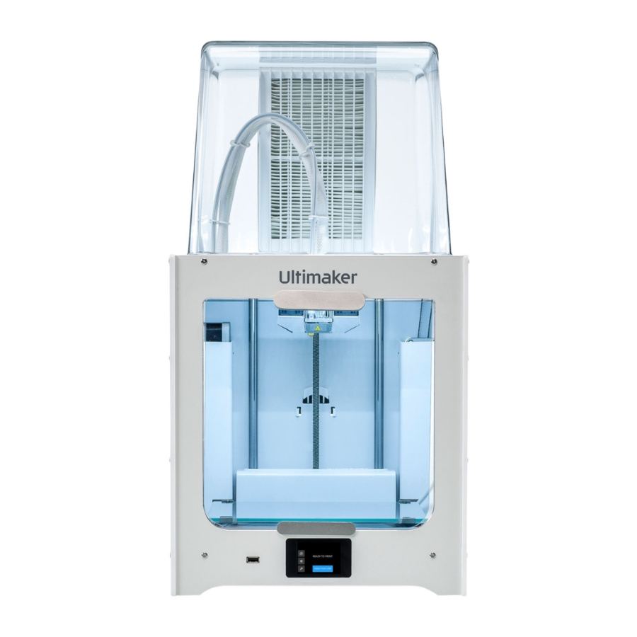
Ultimaker 2+ Connect Manual
Also See for 2+ Connect:
- User manual ,
- Calibration manual (9 pages) ,
- Repair manual (9 pages)
Advertisement
Table of Contents
Ultimaker 2+ Connect Manual

Required
Tools
- ESD prevention supplies
- 2.0 mm hex screwdriver
- 2.0 mm hex bit
- Torque screwdriver 0.5 Nm (or adjustable)
- Tweezers or flat-sided screwdriver (optional)
Parts
- 1x 221542 – Connectivity board assembly
Time
- 10 minutes
Notes
Make sure the filament is unloaded, the Ultimaker 2+ Connect is turned off, and the power cable is disconnected before you start the replacement.
This repair involves working with or exposing sensitive electronic components. Take ESD precautions before starting this procedure.
Tip: All orientations are as seen from the front in the upright orientation, unless specified otherwise.
Disassembly
- Place the printer on its left side, with the bottom facing towards you
Do not place the printer on its back; this is unstable and can damage the feeder
![Ultimaker - 2+ Connect - Disassembly - Step 1 Disassembly - Step 1]()
- Loosen the two M3x6 bolts at the front that secure the bottom cover
Tools: 2.0 mm hex screwdriver
Tip: The smaller hole in the cover is for the reset button and does not contain a bolt
![Ultimaker - 2+ Connect - Disassembly - Step 2 Disassembly - Step 2]()
- Pull the front of the cover towards you, and pull the two tabs of the cover out of the back panel
Tip: Place the bottom cover and the two bolts aside; make sure to keep the bolts somewhere safe so you do not lose them during the repair process
![]()
The connectivity board is the PCB located at the front of the printer
![Ultimaker - 2+ Connect - Disassembly - Step 3 Disassembly - Step 3]()
- Press the lip on the Ethernet cable and disconnect the cable from the connectivity board
Tip: You do not need to open any of the cable clips
![Ultimaker - 2+ Connect - Disassembly - Step 4 Disassembly - Step 4]()
- Disconnect the gray ribbon cable from the connectivity board
![Ultimaker - 2+ Connect - Disassembly - Step 5 Disassembly - Step 5]()
- Carefully open the two small connectors that hold the display cables
Tip: Use your nails, tweezers, or a flat-sided screwdriver to push the latch open
Be very careful; these connectors are fragile
![Ultimaker - 2+ Connect - Disassembly - Step 6 Disassembly - Step 6]()
- Fully open the connectors and remove the two display cables
Tools: 2.0 mm hex screwdriver
![Ultimaker - 2+ Connect - Disassembly - Step 7 Disassembly - Step 7]()
- Remove the four M3x12 bolts that secure the connectivity board to the bottom panel
Tools: 2.0 mm hex screwdriver
![Ultimaker - 2+ Connect - Disassembly - Step 8 Disassembly - Step 8]()
- Take out the connectivity board assembly
![Ultimaker - 2+ Connect - Disassembly - Step 9 Disassembly - Step 9]()
Reassembly
- Align the new connectivity board assembly with the inserts in the bottom panel
Tip: Don't remove the board from the ESD bag until just before installing it
Ensure the display cables don't get stuck behind the board
![Ultimaker - 2+ Connect - Reassembly - Step 1 Reassembly - Step 1]()
- Secure the board to the bottom panel with the four M3x12 bolts
Tools: Torque screwdriver with hex 2.0 mm bit, 0.5 Nm
![Ultimaker - 2+ Connect - Reassembly - Step 2 Reassembly - Step 2]()
- Carefully insert the two display cables to their corresponding connectors
Note: Small = touch, large = display
![Ultimaker - 2+ Connect - Reassembly - Step 3 Reassembly - Step 3]()
- Push the latches fully closed to secure the cables
Note: Ensure the cables remain fully inserted while closing the connectors
![Ultimaker - 2+ Connect - Reassembly - Step 4 Reassembly - Step 4]()
- Connect the Ethernet cable so that it clicks into place
![Ultimaker - 2+ Connect - Reassembly - Step 5 Reassembly - Step 5]()
- Connect the ribbon cable to the black connector at the side of the board
![Ultimaker - 2+ Connect - Reassembly - Step 6 Reassembly - Step 6]()
- Align the tabs at the back of the bottom cover with the slots in the back panel
Mind all the wires and ensure nothing gets pinched between the cover and the frame
![]()
- Close the bottom cover and secure it with the two M3x6 bolts
Tools: 2.0 mm hex screwdriver
![Ultimaker - 2+ Connect - Reassembly - Step 7 Reassembly - Step 7]()
- Place the printer upright again
![Ultimaker - 2+ Connect - Reassembly - Step 8 Reassembly - Step 8]()
Finished!
After replacing the connectivity board, the following actions and checks are recommended:

- Update the firmware to the latest version
- Connect the printer to the network
- Run a (quick) test print
Documents / ResourcesDownload manual
Here you can download full pdf version of manual, it may contain additional safety instructions, warranty information, FCC rules, etc.
Advertisement


Need help?
Do you have a question about the 2+ Connect and is the answer not in the manual?
Questions and answers