
Related Manuals for Zip HydraTap G5 CS100


Summary of Contents for Zip HydraTap G5 CS100
- Page 1 Installation instructions HydroTap G5 ® Model : CS100 Command Centre 810002 v3.00 08.24 G5 CS COMM Online install instructions...
-
Page 2: Table Of Contents
INSTALLATION INSTRUCTIONS Table of contents Using these instructions ....................3 Explanation of symbols ............................3 Safety instructions ..............................3 Section 1 IMPORTANT SAFETY INSTRUCTIONS ..............3 Warnings and regulatory information ................6 Technical data ........................8 Supplied parts checklist ....................9 Installation checklist .......................10 Before installation ......................11 General product features .................... -
Page 3: Using These Instructions
Refrigerant WARNING! KEEP VENTILATION OPENINGS IN THE APPLIANCE ENCLOSURE OR IN THE BUILT-IN STRUCTURE CLEAR OF OBSTRUCTION. The Zip HydroTap Command Centre range uses HIGHLY FLAMMABLE R290 refrigerant under pressure. Check the rating plate or contact Zip before commencing work. - Page 4 Airflow The Zip HydroTap operates within the ambient temperature range 5ºC - 35ºC. Proper air circulation must be provided. The system will operate satisfactorily only if the recommended air gaps are provided. The vent kit supplied must be fitted.
- Page 5 IMPORTANT SAFETY INSTRUCTIONS Compressed gas warning - HydroTap Clean can • Read label before use. • Keep out of reach of children. • Use according to SDS (safety data sheet). • Pressurised container. Contains gas under pressure,may explode if heated. •...
-
Page 6: Warnings And Regulatory Information
• The power cord and general power outlet must be in a safe and accessible position after installation. When positioning the appliance, ensure the power supply cord is not trapped or damaged. If the power supply cord is damaged it must be replaced by a Zip service provider or a qualified electrician. - Page 7 WARNINGS AND REGULATORY INFORMATION • BS6920:2014 ‘Suitability of non metallic materials and products for use in contact with water intended for human consumption with regard to their effect on the quality of water'. • Use the new hose set supplied with the unit. Do not re-use old hose set. •...
-
Page 8: Technical Data
Technical data Technical data table Dimensions Power rating kW Power rating kW Weight Model W x D x H (mm) 220-240V 50Hz 220V 60Hz (kg) Command Centre only Chilled Sparkling models CS100 0.37 0.41 280 x 499 x 333 36.5 Electricity supply requirements 220-240V 50Hz AC (for power requirement see table above). -
Page 9: Supplied Parts Checklist
Lime scale filter kit Font Font kit Optional Note Mains water isolation valve is not supplied with the kit. Contact Zip for the full range of consumables and accessories. 810002 v3.00 08.24 G5 CS COMM Online install instructions... -
Page 10: Installation Checklist
Installation checklist • Check if there is adequate space to install all of the components. • Note Not all fittings are supplied with the appliance kit. Isolation valves are not supplied. • Check the mains water pressure is within min / max requirements. •... -
Page 11: Before Installation
Before installation • Review of all the technical specifications. • Ensure the under counter cupboard floor can support the product weight when full of water (allow an extra 3-8kg when full). • Sufficient space in the cupboard to install the Command Centre and other components in accordance with these installation instructions. -
Page 12: General Product Features
General product features Thank you for purchasing a Zip HydroTap G5. Please read and follow these instructions carefully to ensure safe and trouble free operation. If help and advice is required, contact your local service provider. What is the Zip HydroTap G5 ? This Zip HydroTap G5 is an electronically controlled, filtered, boiling, chilled and sparkling (functionality is dependant upon model purchased) drinking water system for the kitchen. -
Page 13: Section 2 Ventilation
Section 2 Ventilation Read and use the instructions and safety information supplied with individual kit components for a safe installation. Clearance envelope & airflow The integrated vent aperture must be cut out of the cupboard floor & mounting plate fitted. The vent provides a safe exhaust for the refrigerant gas in the unlikely event of a leak. - Page 14 Section 2 Ventilation CS100 ventilation options Vent grilles & plates cut-outs Option 1: Ventilation arrangement using large cupboard with For integrated vent cut-out, check min. 40mm overhang Directing warm air straight into the room. size relative to your product. Must be installed For Command Centre width 280mm C l e a r a...
- Page 15 Section 2 Ventilation CS100 ventilation options, continued Option 3: Ventilation arrangement if using a large cupboard with less than 40mm, or no overhang. Directing warm air into the kick space & out through a vent grille. Must be installed Must be installed C l e a r a Inlet...
-
Page 16: Section 3 Ancillary Installations - Install Rail Installation (Uk Only)
Section 3 Ancillary Installations - Install Rail installation (UK only) Description • The install rails can be used to safely connect a wide range of water appliances to the mains water supply. The install rails include an isolation valve, double check valves, tamper proof pressure reducing valve pre- set to 0.3 MPa and a flood preventer with reset. -
Page 17: Section 3 Ancillary Installations - Connect To The Water Supply
Section 3 Ancillary Installations - Connect to the water supply Connect the braided hose to the mains water supply Valves and fittings must be sealed with PTFE tape if compression seals are not included. Note correct strainer orientation. Note Mixer tap installations also use a ‘Tee piece’ as part of the water supply plumbing connections, see the Tap installation instructions supplied with the Mixer Tap to connect the water supply if using the mixer tap option. -
Page 18: Secure The Cylinder
Section 3 Ancillary Installations - CO cylinder and regulator Be aware of the risks of hazards which could cause harm when handling compressed CO2. Read the safety warnings at the start of this instruction manual. Assess the risks before starting the installation. -
Page 19: Fit The Regulator And Connect The Gas Hose
Section 3 Ancillary Installations - CO cylinder and regulator Fit the regulator and connect the gas hose • Ensure all mating surfaces are clean. • Turn the regulator OFF, (fully anticlockwise). • Check the regulator and hose seals, inside the connectors. •... -
Page 20: Adjust The Universal G5 Regulator
Section 3 Ancillary Installations - CO cylinder and regulator Adjust the Universal G5 regulator Cylinder pressure • Check the regulator is turned all the way OFF (anti-clockwise). • Turn the gas ON using the cylinder valve, Outlet (anti-clockwise). (dual-gauge regulator). pressure •... -
Page 21: Section 4 Command Centre Installation
Section 4 Command Centre installation Generic installation arrangement instructions Read these instructions together with those supplied with individual components before commencing Command Centre installation,they apply to all installation arrangements. • Install the mains water braided hoses to the Command Centre before locating in place. -
Page 22: Position Of Carbonation Flow Valve (Sparkling Models)
Section 4 Command Centre installation Position of carbonation flow valve (sparkling models) For optimal Sparkling Water from your HydroTap, follow these directions to position the carbonation flow valve between the HydroTap Command Centre and the dispensing tap. It is essential to adjust the carbonation valve for optimal sparkling water dispense, see page 35. -
Page 23: John Guest Pipe And Fittings
Section 4 Command Centre installation John Guest pipe and fittings Take care to use correctly, see below : Insert Remove 2. Pull pipe 1. Cut pipe clean & square 1. Press collet 2. Push pipe to down end stop Mains power cable Do not connect to the mains socket until commissioning Connect Command Centre to HydroTap. -
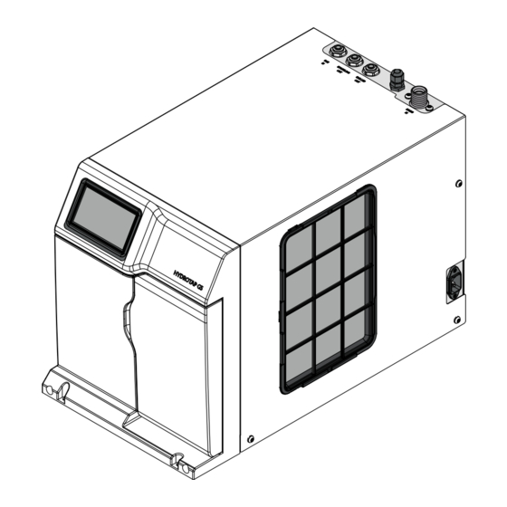
Page 24: Cs100 Models, General Layout
Section 4 Command Centre installation CS100 models, general layout Command Centre Mains electrical power connector *CO2 cylinder *CO2 regulator Tap - Command Centre USB Carbonation valve Mains water supply Tap & CO2 connections Mains braided hose - Command Centre manifold regulator Mains braided hose - Command Centre Note *CO2 cylinder and regulator sizes vary,... -
Page 25: Cs100 Models With Celsius Tap, General Layout
Section 4 Command Centre installation CS100 models with Celsius tap, general layout Command Centre Mains electrical power connector *CO2 cylinder *CO2 regulator Tap - Command Centre USB Carbonation valve Mains water supply Tap & CO2 connections Mains braided hose - Command Centre manifold regulator Note *CO2 cylinder and regulator sizes vary,... -
Page 26: Cs100 Hydrotap G5 Models
B res comm Section 4 Command Centre installation CS100 HydroTap G5 models MAINS MIXER MIXER BOILING BYPASS VENT BYPASS Command Centre connections Braided hose HydroTap C 175 comm Connections key Fit foam insulation (supplied) to CHILLED MAINS Mains the BLUE and WHITE pipes OUTLET CS 175 comm SPARKLING... -
Page 27: Cs100 Chilled, Sparkling And Mixed Hot & Cold
B res comm Section 4 Command Centre installation CS100 Chilled, sparkling and mixed hot & cold MAINS MIXER MIXER BOILING BYPASS VENT BYPASS Command Centre connections Braided hose HydroTap C 175 comm Connections key Fit foam insulation (supplied) to CHILLED MAINS Mains the BLUE and WHITE pipes... -
Page 28: Section 5 Commissioning
Section 5 Commissioning Commissioning using the HydroTap Clean can The HydroTap Clean process HydroTap Clean is a first to market cleaning process for HydroTap systems comprised of the HydroTap Clean solution, dosing adaptor and smart firmware. The HydroTap Clean process is automated and gently cleans the chilled and sparkling water paths during the commissioning of a new HydroTap Command Centre. -
Page 29: Select The Language
Section 5 Commissioning Select the language • Touch the appropriate button to select the language and units of LANGUAGE 10:50 choice. • Touch the back arrow to go back to previous menu. • In the previous menu, touch the arrow to begin the commissioning process. - Page 30 Section 5 Commissioning Set the date, time & drain away options • Touch the date and time, use "-" or "+" to make adjustments. When DATE & TIME 10:50 ready, touch the arrow to continue. 2021 24 hr Time • Select 'Sink / Container' or 'Font' depending on the model , see DRAIN AWAY OPTION 9:26 below.
- Page 31 Section 5 Commissioning FILTER FLUSH 12:12 PM FILTER HAS BEEN FLUSHED! Turn the flush line STOP COCK VALVE back to the OFF position Your filter has now been flushed and is ready to use. You will need to check the life span of the filter in filter settings •...
- Page 32 Section 5 Commissioning Cleaning preparation HYDROTAP CLEAN PREPARATION 12:12 PM • Read the on screen information. Step 1. Insert cloth below filter. Step 2. Remove filter and refit dust cap. • Place a cloth under the filter. • Remove the filter, refit the dust cap, and set aside in a clean environment.
- Page 33 Section 5 Commissioning Filter head and HydroTap Clean adapter (1) • Screw the HydroTap Clean can (2) into the adapter (already installed into the filter head). HydroTap Clean can (2) • Confirm installation of the HydroTap Clean can by selecting YES HYDROTAP CLEAN PREPARATION 12:12 PM on the screen.
- Page 34 Section 5 Commissioning • This screen is shown after completion of the cleaning process. 12:12 PM RE-INSTALL FILTER If the below steps have not been completed. Follow the instructions below. Step 1. Ensure cloth is below HydroTap Clean can (2). Step 2.
-
Page 35: Tank Flush
Section 5 Commissioning Tank flush • Read the on screen information and instructions. TANK FLUSH 12:12 PM • Touch the green arrow to run. Fresh water will be flushed through the tank/s multipe times as shown by the cycle counter/s. Enabling ‘Auto Dispense’... -
Page 36: Section 6 Service And Trouble Shooting
Section 6 Service and Trouble shooting Service items • Filters should be replaced at six month intervals for Commercial HydroTaps, and 12 month intervals for Residential HydroTaps. • CO2 regulator washers should be replaced annually. Trouble shooting table Fault Fault name Fault trigger code Power Board Fault... -
Page 37: Section 7 Operation And Maintenance
The Zip filter should be replaced as recommended on the filter label, or earlier if you notice a persistent reduction in water flow from the tap or an increase in chlorine, taste or odour in the water. Not changing the filter cartridges when required may affect the water quality. -
Page 38: Section 8 End Of Life Disposal
Section 8 End of life disposal Waste electrical and electronic equipment The symbol above means that according to United Kingdom and European Union member countries laws and regulations, your product and /or its battery shall be disposed of separately from household waste. When this product reaches its end of life, take it to a collection point designated by local authorities. - Page 39 Free Call (Aust): 1800 947 827 www.zipwater.com As Zip policy is one of continuous product improvement, changes to specifications may be made without prior notice. Images in this booklet have been modified and may not be true representations of the finished goods.
Need help?
Do you have a question about the HydraTap G5 CS100 and is the answer not in the manual?
Questions and answers