Table of Contents
Advertisement
Installation instructions
Zip
HydroTap G4
The Worlds most advanced Drinking Water Appliance
Model :
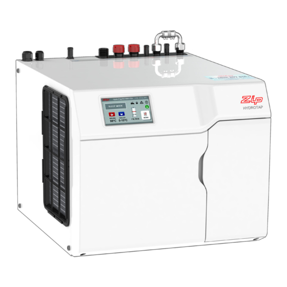
Command Centre
VENTILATION
IS ESSENTIAL
READ SECTION 1
'VENTILATION'
BEFORE YOU START
Installation instructions
805845UK v1.02 July 2018 - G4 Command Centre
®
(see table of contents for specific models)
Tel: 0345 6 005 005 Email: service@zipindustries.co.uk www.zipwater.co.uk
Technical support
1
Advertisement
Table of Contents

Related Manuals for Zip 5253UK


Summary of Contents for Zip 5253UK
- Page 1 Installation instructions HydroTap G4 ® The Worlds most advanced Drinking Water Appliance Model : Command Centre (see table of contents for specific models) VENTILATION IS ESSENTIAL READ SECTION 1 ‘VENTILATION’ BEFORE YOU START Installation instructions Technical support 805845UK v1.02 July 2018 - G4 Command Centre Tel: 0345 6 005 005 Email: service@zipindustries.co.uk www.zipwater.co.uk...
- Page 2 Tap options The G4 series offers a range of interchangeable taps to suit the customer's needs. Classic range These standalone taps offer instant boiling, chilled and sparkling water* and are directly compatible with the G4 Command Centre. Arc / Cube range Elite range The mixer tap range may be used in conjunction with any of the above to provide mixed hot and cold water...
-
Page 3: Table Of Contents
Section 7.1 - Generic Command Centre installation instructions ..........30 Section 7.2 - External bypass valve ..................... 31 Section 7.3 - 5253UK & 5053UK BCS commercial installation ............ 33 Section 7.4 - 2957UK, 2857UK, 1456UK & 1256UK BCS comm. and res. compact installation . 38 Section 7.5 - 5261UK &... -
Page 4: Installation Checklist
Installation checklist Before installation • Read the instructions and check if there is adequate space to install all of the components. Note Not all fittings are supplied with the appliance kit. Isolation valves are not supplied. • • Check the mains water pressure is within min / max requirements (see page 11). •... -
Page 5: General Product Features
These units are NOT designed to be used solely as sanitary fixtures. The Zip HydroTap G4 models which dispense boiling water are fitted with a tap mounted safety lock. In addition, there are various energy saving options accessible via the main menu. The system is equipped with a self-calibrating program which caters for altitude adjustment. -
Page 6: Important Safety Instructions
11, for the weight of the product. Airflow The Zip HydroTap G4 operates within the ambient temperature range 5ºC - 35ºC. Proper air circulation must be provided. The system will operate satisfactorily only if the recommended air gaps are provided. See Section 1 'Ventilation', page 13, for correct installation to prevent overheating. -
Page 7: Warnings And Regulatory Information
WARNINGS AND REGULATORY INFORMATION Warnings • The Zip HydroTap G4 must be earthed. The resistance of the earth connection from each exposed metal part must be less than 1Ω. • All installation and service work must be completed by trained and suitably qualified tradespeople. -
Page 8: Major Components And Accessories
For Zip HydroTap 240/175 models, two 220-240Vac, 10A GPOs will be CLAMP AV160/125G4 required. (One GPO is for the Zip HydroTap and the other for the Booster heater). NOTE: feed each of the three tubes and NOTE: Check the cable lengths and outlet positions before proceeding. -
Page 9: Tap - Command Centre Compatibility
Tap - Command Centre compatibility Commercial B, BA, BC and BCS HydroTap G4 range HydroTaps Filtered Boiling Filtered Boiling and Ambient Filtered Boiling and Chilled Filtered Boiling, Chilled and Sparkling Arc / Cube Elite Classic Mixer taps Plus unfiltered Hot and Cold. Classic Vented All-in-One Classic Filtered Boiling and Chilled plus unfiltered Hot and Cold... - Page 10 Tap - Command Centre compatibility Residential B, BA, BC and BCS HydroTap G4 range HydroTaps Filtered Boiling Filtered Boiling and Ambient Filtered Boiling and Chilled Filtered Boiling, Chilled and Sparkling Arc / Cube Elite Classic Mixer taps Plus unfiltered Hot and Cold Arc Mains Cube Mains All-in-One taps...
-
Page 11: Technical Specifications
(10A) /hr) (200ml duct (kg) 230V 230V glasses/hr) Commercial Command Centres Filtered Boiling, Chilled and Sparkling, with and without booster 5253UK 160 / 240* 2.30 2.20 optional 1 / 2* 450 x 470 x 335 5053UK 2957UK 100 / 140* 2.13... -
Page 12: Before Installation And Site Requirements
Technical specification, page 11 for dimensions. Make allowance for a booster if required. See sections 2 page 21 for installation instructions. • For Zip HydroTap G4 models without booster, 1 x 220-240V AC 13A socket will be required. For Zip HydroTap G4 models with booster, 2 x 220-240V AC 13A sockets will be required. -
Page 13: Section 1.1 - 1.9 Ventilation For All Models
Section 1 Ventilation Ventilation table of contents 1.1 Generic requirements ......................13 1.2 BC,BCS Commercial Command Centre installation .............. 14 1.3 BC, BCS Commercial compact Command Centre installation ..........16 1.4 BO,BA Commercial and Residential Command Centre installation ........17 1.5 CS, C Commercial Command Centre installation .............. - Page 14 Ventilation 1.2 BC, BCS Commercial Command Centres 1.2.1 Ventilation for all models • The clearance envelope dimensions stated in the Specification sheets and Installation instructions must be observed. • Adequate ventilation must be provided to ensure that the cupboard temperature doesn't exceed 35 1.2.2 Preferred ventilation arrangement shown below.
- Page 15 (e.g. hospitals) use a Vent tray kit Call Zip on 0345 6 005 005. A vent grille, supplied should be used as an inlet vent and fitted to the cabinet side (adjacent to the Command Centre air inlet) as shown below.
- Page 16 Ventilation 1.3 BC, BCS Commercial compact Command Centres 1.3.1 Ventilation for all models • The clearance envelope dimensions stated in the specification sheets and installation instructions must be observed. • Adequate ventilation must be provided to ensure that the cupboard space temperature does not exceed 1.3.2 Preferred arrangement •...
- Page 17 Ventilation 1.4 BO & BA Commercial, BO & BA Residential Command Centres 1.4.1 Ventilation for all models • The clearance envelope dimensions stated in the specification sheets and installation instructions must be observed. • Adequate ventilation must be provided to ensure that the cupboard space temperature does not exceed 1.4.2 Preferred arrangement •...
- Page 18 Ventilation 1.5 CS & C Commercial Command Centres 1.5.1 Ventilation for all models • The clearance envelope dimensions stated in the specification sheets and installation instructions must be observed. • Adequate ventilation must be provided to ensure that the cupboard space temperature does not exceed 1.5.2 Preferred ventilation arrangements for CS models The ducted vent kit supplied with the Command Centre exhausting through the kick-space should be used, to provide adequate ventilation in all conditions.
- Page 19 Ventilation 1.5.3 Alternative arrangement (Dual fan kit) In situations where the preferred arrangement cannot be used or will not work effectively e.g. Single cupboard where the 100mm grille spacing cannot be achieved. • Where there are openings in the back of the cupboard allowing exhaust air to recirculate into the cupboard •...
- Page 20 Ventilation 1.6 BC, BCS, CS, C Residential Command Centres 1.6.1 Ventilation for all models • The clearance envelope dimensions stated in the specification sheets and installation instructions must be observed. • Adequate ventilation must be provided to ensure that the cupboard space temperature does not exceed 1.6.2 Preferred arrangements 4mm door buffers (at the four corners of each door) supplied with the Command Centre should be used to provide adequate ventilation in normal usage, see illustration below.
-
Page 21: Section 2 - Booster Installation
The booster system is a compact electronically controlled auxiliary water heater. It is intended to provide pre-heating of water before it enters the Zip HydroTap G4 boiling tank. If the booster is used the boiling water output will be increased. - Page 22 Booster system 2.2 Installation procedure Site requirements • Booster must only be installed in a frost-free area. Never expose booster to frost. • The booster is designed for wall mounted installation and must be installed with water connectors facing upwards. •...
- Page 23 Note 1 This appliance is intended for use with the Zip HydroTap G4 Command Centre Note 2 Water connections must be pointing vertically upwards. Note 3 The booster unit should be installed as close as possible to the Zip HydroTap G4 as the 500mm connection hoses cannot be lengthened.
-
Page 24: Section 3 - Scale Filter Installation
• Zip scale filter cartridge installation and operating instructions 2017, supplied with the filter cartridge. • Zip scale filter head installation and operating instructions 2017, supplied with the filter head. Flush valve Outlet (To Bypass in) -
Page 25: Section 4 - Co 2 Cylinder Installation
Section 4 Cylinder installation STORAGE WARNING The cylinder contains 1.2kg of CO and should be installed in a well ventilated area. You can have serious health problems if breathing air containing concentrations of CO up to 15000ppm (1.5%) for more than 10 minutes. Proper ventilation must be provided to ensure that, in case of escape, concentrations of CO remain below this level. - Page 26 Regulator Note When removing hose, take care not to lose plastic olive from the fitting. Leak test After replacing a cylinder or after making a gas connection, perform a leak test to check for gas leaks between regulator and cylinder, and between regulator and braided hose.
-
Page 27: Section 5 Water Block Installation
Section 5 Water block installation 5.1 Description • The Water Block is designed to be installed upstream of any Zip product and associated pipe-work to minimise the potential for water leakage in the event of a system malfunction. • The Water Block is ideal for limiting potential leakage and resulting water damage from water heaters, water chillers etc. - Page 28 The reset device (see Fig.2) may be fitted to avoid disconnection. This allows the Water Block to be reset by operating the lever in the direction shown in Fig.2. • In the event of persistent tripping contact Zip for advice on 0345 6 005 005. 5.6 Maintenance •...
-
Page 29: Section 6 Carbonation Valve Installation
Section 6 Carbonation valve installation • Fitted in sparkling systems only 6.1 Description The carbonation valve has been designed to provide the installer with the ability to preset the level of carbonation of the sparkling water, to the taste of the user. The carbonation valve can be fitted at the time of installation, or retrofitted to G4 Command Centres previously installed.
Need help?
Do you have a question about the 5253UK and is the answer not in the manual?
Questions and answers