Renogy Battery Shunt 300 (RSHST-B02P300-G1) Manual
- Quick manual (27 pages) ,
- User manual (34 pages)
Advertisement
- 1 General Information
- 2 Get to Know Renogy Battery Shunt 300
- 3 Preparation
-
4
Installation
- 4.1 Remove the Covers
- 4.2 Connect the Shunt to the Auxiliary Battery Negative
- 4.3 Connect the Shunt to the Device AUX BAT-
- 4.4 Connect the Shunt to the Auxiliary Battery Positive
- 4.5 Install a Battery Temperature Sensor
- 4.6 Connect the Shunt to the Starter Battery Positive
- 4.7 Mount the Shunt
- 4.8 Install the Covers
- 5 Configuration
- 6 LED Indicators
- 7 Troubleshooting
- 8 FAQ
- 9 Dimensions and Specifications
- 10 Maintenance
- 11 Emergency Responses
- 12 Renogy Support
- 13 Documents / Resources
General Information
Symbols Used
The following symbols are used throughout the user manual to highlight important information.

Indicates a potentially dangerous condition which could result in injury or death.

Indicates a critical procedure for safe and proper installation and operation.
 Indicates an important step or tip for optimal performance.
Introduction
Renogy Battery Shunt 300 is an intelligent battery monitor that measures the battery voltage and current based on which it calculates the state of charge (SOC) and remaining running time of the battery.
In addition, the shunt records historical charging and discharging data such as full deep discharge cycle, discharge capacity, charge cycle, and battery temperature.
With the built-in Bluetooth module, Battery Shunt 300 communicates with the DC Home app and Renogy ONE. This allows you to monitor real-time charging and discharging data and customize related parameters. These settings encompass nominal capacity, deep discharge thresholds, temperature alarms, and SOC alarms.
Key Features
- Universal Battery Compatibility
Works seamlessly with various battery types, including Lead Acid (AGM, GEL), Lithium Iron Phosphate, Lithium-ion, and Nickel-metal hybrid. - Comprehensive Battery Insights
Provides vital battery information such as State of Charge (SOC), voltage, current, energy, remaining time, temperature, and starter battery voltage. - Alarm and Historical Data
Records historical data and offers alerts for abnormal conditions through the DC Home app. - Convenient Remote Monitoring
Enables remote monitoring and control via Renogy ONE and the DC Home App using Bluetooth connectivity. - Effortless Installation and Configuration
Simplifies installation and settings adjustments through the DC Home app for a user-friendly experience.
SKU
| Renogy Battery Shunt 300 | RSHST-B02P300-G1 |
Get to Know Renogy Battery Shunt 300
What's In the Box

Make sure that all accessories are complete and free of any signs of damage.
The accessories and product manual listed are crucial for the installation, excluding warranty information and any additional items. Please note that the package contents may vary depending on the specific product model.
Required Tools & Accessories

Prior to installing and configuring the shunt, prepare the recommended tools, components, and accessories.
For how to size bare wires, refer to "Size Bare Wires" in this manual.
For how to install 3/8 in Lugs (M10 Ring Terminals), see "How to Install 3/8 in Lugs" in this manual.
For connection methods and required tools for the auxiliary battery, starter battery, and equipment terminal, please refer to the user manual of the specific device. The diagrams provided within this manual are for illustrative purposes only.
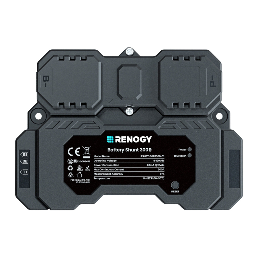
Product Overview
Exterior

Interior (with the covers removed)

System Setup
Connecting to a Auxiliary Battery Only

Connecting to Both a Auxiliary Battery and a Starter Battery
The AUX BAT+ and AUX BAT- refer to the terminals of a specific device through which the device is connected to the positive and negative terminals of an auxiliary battery, respectively.

In such scenario, the shunt detects voltage of both the auxiliary battery and the starter battery.
Connecting to Multiple Auxiliary Batteries
The illustrations depict two batteries in parallel as an example. There is no limit on the number of batteries in parallel. You can customize the setup with more batteries as needed.
Please ensure the combined continuous current from the batteries must not surpass 300A, maintaining a voltage below 120V.
Auxiliary batteries in parallel
The AUX BAT+ and AUX BAT- refer to the terminals of a specific device through which the device is connected to the positive and negative terminals of an auxiliary battery, respectively.

You can connect the Battery Shunt 300 to a starter battery via the B2 port on demand.
The illustrations depict two batteries in series as an example. There is no limit on the number of batteries in series. You can customize the setup with more batteries as needed.
Please ensure the continuous current from the batteries must not surpass 300A, maintaining a total voltage below 120V.
Auxiliary batteries in series
The AUX BAT+ and AUX BAT- refer to the terminals of a specific device through which the device is connected to the positive and negative terminals of an auxiliary battery, respectively.

You can connect the Battery Shunt 300 to a starter battery via the B2 port on demand.
Preparation
Plan a Mounting Site
Select a proper mounting site to ensure the shunt can be safely connected to the battery and other necessary devices with the relevant cables. Install the shunt in a clean, cool, and dry location, free from any accumulation of water, oil, or dirt. For optimal Bluetooth communication, avoid placing the battery shunt near metal objects.

 Install the Renogy Battery Shunt 300 indoors and prevent its components from being exposed to direct sunlight.
Do not expose Renogy Battery Shunt 300 to flammable or harsh chemicals or vapors.
Keep Renogy Battery Shunt 300 out of the reach of children.
Make sure that the Renogy Battery Shunt 300 is installed with ambient temperature range from -4°F to 122°F or -20°C to 50°C.
Make sure that the Renogy Battery Shunt 300 is installed in an environment with relative humidity between 0% and 95% and no condensation.
Check Renogy Battery Shunt 300
Inspect the shunt for any visible damage including cracks, dents, deformation, and other visible abnormalities. All connector contacts shall be clean, dry, and free of dirt and corrosion.

Do not use Renogy Battery Shunt 300 if it appears to be damaged.
There are no serviceable parts in Renogy Battery Shunt 300. Do not open, dismantle, repair, tamper with, or modify it.
Wear proper protective equipment and use insulated tools during installation.
Do not dispose of Renogy Battery Shunt 300 as household waste. Comply with local, state, and federal laws and regulations and use recycling channels as required.
Check System Voltage and Current
Ensure the battery shunt operates within a power system with a maximum system voltage of 120V and a continuous current of up to 300A. Exceeding these voltage and current limits may cause damage to the shunt.

 Risk of electric shock! Before installing the shunt, please turn off all devices within the system and ensure there is no current flowing through the circuit.
Size Bare Wires
Select proper bare wires based on the ampacity in your power system. Refer to the table below for copper cable ampacities with different gauge sizes.
| Cable Gauge Size | Ampacity |
| 14 AWG (2.08 mm²) | 35A |
| 12 AWG (3.31 mm²) | 40A |
| 10 AWG (5.25 mm²) | 55A |
| 8 AWG (8.36 mm²) | 80A |
| 6 AWG (13.3 mm²) | 105A |
| 4 AWG (21.1 mm²) | 140A |
| 2 AWG (33.6 mm²) | 190A |
| 1 AWG (42.4 mm²) | 220A |
| 1/0 AWG (53.5 mm²) | 260A |
| 2/0 AWG (67.4 mm²) | 300A |
| 4/0 AWG (107 mm²) | 405A |
The above values are from the NEC Table 310.17 for copper cables rated at 194°F (90°C), operating at an ambient temperature of no more than 86°F (30°C). Cables longer than 13 feet (4000 mm) may require thicker gauge wires to prevent excessive voltage drop in undersized wiring.
How to Install 3/8 in Lugs
If a suitable battery tray cable isn't available, you can customize one by following the steps below:
- Strip approximately 0.4 inches (10 mm) of insulation from the end of a bare wire using a wire stripper.
![]()
- Thread the exposed bare wire through a piece of heat shrink tubing.
![]()
- Attach a 3/8-inch lug onto the end of the bare wire.
![]()
- Securely crimp the lug onto the bare wire using a manual hydraulic pliers.

- Slide the heat shrink tubing over the 3/8-inch lug.
![]()
- Apply heat to the heat shrink tubing using a heat gun until it shrinks and forms a tight seal.


Installation
To ensure safe and efficient operation of the battery shunt and to avoid potential damage or hazards, always follow the installation instructions in the sequence described in this manual.
Wear Insulating Gloves

Remove the Covers
Remove the Upper Cover

Remove the Lower Cover

Connect the Shunt to the Auxiliary Battery Negative

Connect the Shunt to the Device AUX BAT-

Connect the Shunt to the Auxiliary Battery Positive

Install a Battery Temperature Sensor

Connect the Shunt to the Starter Battery Positive
(Optional)

Mount the Shunt
(Optional)
To guarantee system safety, mounting the shunt to a proper location is recommended. You can choose a proper mounting site on demand.

Install the Covers
Install the Lower Cover

Install the Upper Cover (Optional)

Installing the Upper Cover is optional in cases where the terminals are not enclosed by the cover.
Configuration
Power On
Power on all devices in your power system, and the Battery Shunt is powered up automatically with the Power LED Indicator lighting up.

Pairing with DC Home or Renogy ONE
For initial use, set the "Rated Battery Ah" (rated battery capacity) on the app prior to other operations. Rated Battery Ah should be the same as the rated capacity of the specific battery you use. For details, refer to the battery user manual.
Initial Paring
For initial startup, follow the steps below to pair the shunt with the DC Home app or Renogy ONE.
- On DC Home or Renogy ONE, navigate to "Add Devices".
![]()
- Scan and pair the shunt with the Renogy ONE or DC Home app.
![]()


Pairing with Another Device
- Remove the shunt from the DC Home app or ONE. Alternatively, you can press and hold RESET on the shunt for 5s.

- After the Bluetooth LED turns off, redo scanning and pairing.


Energy Monitoring
Depending on the specific application, the shunt can establish either short-range or long-range communication connections with monitoring devices. These monitoring devices including RENOGY ONE Core and DC Home facilitate real-time monitoring, programming, and complete system management, offering comprehensive control and enhanced flexibility.
The version of the DC Home app might have been updated. Illustrations in the user manual are for reference only. Follow the instructions based on the current app version.
Download and login to the DC Home app.


Short-Range Monitoring via DC Home App

Wireless Long-Range Monitoring
If long-range communication and programming are required, connect the shunt to RENOGY ONE Core (sold separately) through Bluetooth, and the RENOGY ONE Core to the DC Home app through Wi-Fi.
Recommended Components

Components marked with "*" are available on renogy.com.
For instructions on Renogy ONE Core, see Renogy ONE Core User Manual.
Make sure the shunt does not communicate with any other device.

SOC Synchronization
To ensure reliable readout of the SOC of your battery, SOC synchronization is required, especially for batteries that have been used for an extended period.
A battery's capacity can degrade over time, so even if the battery may charge to full capacity, its actual capacity might not be as high as when it was new. For instance, a new battery rated at a full capacity of 100Ah can only charges to 90Ah after a year of use. In this case, recalibrating the SOC is required, using 90Ah as the new reference point, rather than the original 100Ah.
SOC synchronization should be performed in the following scenarios:
- During the initial shunt installation
- After there has been an interruption in the voltage supply to the DC Home or Renogy ONE
- When the battery has not been fully charged
- When the DC Home or Renogy ONE has not detected that the battery has been fully charged because the "Charging Amps" has been set incorrectly.
In this case, review the settings and make sure the battery regularly receives a full charge.
DC Home app
In the DC Home app, follow the steps below to synchronize the battery SOC in your system:
- Tap the shunt details page. Tap "... > Settings" in the upperright corner of the page.
![]()
- Under "Battery", tap Sync in "SOC sync".
![]()
- You can choose "Sync to 100%", "Sync to 0%", "Customization" or "Cancel". It is recommended that you customize the SOC to match the actual SOC of your battery. Allowed value ranges from 0 to 100.
![]()
- Tap "Sync" to complete the synchronization.
![]()


Renogy ONE
In Renogy ONE, follow the steps below to synchronize the battery SOC in your system:
- Tap the shunt details page. Tap "..." in the upper-right corner of the page.
![]()
- Under "Battery", tap Sync in "SOC sync".
![]()
- You can choose "Sync to 100%", "Sync to 0%", "Customization" or "Cancel". It is recommended that you customize the SOC to match the actual SOC of your battery. Allowed value ranges from 0 to 100.
![]()
- Tap "Sync" to complete the synchronization.
![]()


The version of the DC Home app and Renogy ONE might have been updated. Illustrations in the user manual are for reference only. Follow the instructions based on the current app version.
Essential Alarm Settings
The battery shunt provides diverse alarms to protect your battery from high temperature or voltage. Most settings can stay their factory default, but you can customize them to better serve your needs.
On DC Home app or Renogy ONE Core, go to "... > Settings > Alarm" to configure essential alarms listed in the table below.

| Alarm | Value | Description |
| Low SOC Alarm | Range: 0% to 99%
| The Low SOC Alarm activates when the battery SOC falls below the designated "Trigger Value" threshold and deactivates when the battery SOC surpasses the Release Value. Release Value = Trigger Value + Hysteresis Value Hysteresis value range: 0.5% to 5% |
| High Volts Alarm | Range: 0V to 100V Default High Volts Alarm values vary depending on the connected battery.
| The High Volts Alarm activates when the battery voltage reaches the designated "Trigger Value" threshold and deactivates when the battery voltage drops below the Release Value. Release Value = Trigger Value - Hysteresis Value Hysteresis value range: 0.2V to 5V *The hysteresis value should be consistent with that in Low Volts Alarm. |
| Low Volts Alarm | Range: 0V to 100V Default Low Volts Alarm values vary depending on the connected battery.
| The Low Volts Alarm activates when the battery voltage reaches the designated "Trigger Value" threshold and deactivates when the battery voltage rises above the Release Value. Release Value = Trigger Value + Hysteresis Value Hysteresis value range: 0.2V to 5V *The hysteresis value should be consistent with that in High Volts Alarm. |
| High Charge Amps Alarm | Range: 1A to 300A
| The High Charge Amps Alarm activates when the battery charge current rises above the designated "Trigger Value" threshold and deactivates when the charge current drops below the Release Value. Release Value = Trigger Value - Hysteresis Value Hysteresis value range: 1A to 5A |
| High Discharge Amps Alarm | Range: 1A to 300A
| The High Discharge Amps Alarm activates when the battery discharge current rises above the designated "Trigger Value" threshold and deactivates when the discharge current drops below the Release Value. Release Value = Trigger Value - Hysteresis Value Hysteresis value range: 1A to 5A |
| Battery Low Temp Alarm | Range: -10°C to 60°C (14°F to 140°F)
| The Battery Low Temp Alarm activates when the battery temperature drops below the designated "Trigger Value" threshold and deactivates when the battery temperature rises above the Release Value. Release Value = Trigger Value + Hysteresis Value Hysteresis value range: 1°C to 5°C *The hysteresis value should be consistent with that in Battery High Temp Alarm. |
| Battery High Temp Alarm | Range: -10°C to 60°C (14°F to 140°F)
| The Battery High Temp Alarm activates when the battery temperature rises above the designated "Trigger Value" threshold and deactivates when the battery temperature drops below the Release Value. Release Value = Trigger Value - Hysteresis Value Hysteresis value range: 1°C to 5°C *The hysteresis value should be consistent with that in Battery Low Temp Alarm. |
The value ranges listed in the DC Home app or Renogy ONE Core prevail.
For each alarm, you can choose to either enable or disable the Buzzer when the alarm is triggered.

Historical Data
You can access the historical data of the connected battery via DC Home app or Renogy ONE Core.

The following two parameters should be explained:
- Last Discharged Ah: This value represents the amount of electrical charge (in ampere-hours) that was consumed or discharged from the battery in the last discharge cycle. It is calculated by multiplying the discharge current (in amperes) by the duration of the discharge (in hours).
- Last Charged Ah: This value represents the amount of electrical charge (in ampere-hours) that was added or charged into the battery during the last charging cycle. It is calculated by multiplying the charge current (in amperes) by the duration of the charge (in hours).
Maintaining historical data is essential for diagnosing potential battery issues. Avoid clearing the history unless replacing the battery to preserve valuable information about its performance and behavior over time.
Device Info
In "... > Settings", navigate to "General" where you can:

- Change the display name of your battery shunt
- Access the SN of your battery shunt
- Delete your battery shunt from Renogy ONE
- Reset your historical data.
LED Indicators

Troubleshooting
| Issue | Possible Cause | Solution |
| In DC Home or Renogy ONE, the current is shown as negative when charging and positive when discharging. | Reverse polarity contact | Inspect for reverse contact on B- or P- terminals. |
| Incorrect temperature reading | The temperature sensor wiring is loose. | Confirm the Battery Temperature Sensor is properly installed. |
| Incorrect SOC reading | The battery capacity decreases as the charging and discharging cycles increase. | Re-configure the "Rated Battery Ah" to the capacity when the battery is fully charged. |
| Inaccurate sampling precision in large-current scenarios | Elevated ambient temperatures can affect sampling accuracy. | Ensure proper ventilation for the shunt and remove the upper cover if needed. |
| Abnormal current reading | PFC circuit abnormality or loose terminal connections | Remove the upper cover from the shunt, and check for abnormality on the PFC flexible circuit or loose terminal connections. |
FAQ
What types of battery does the shunt work with?
Battery Shunt 300 works with all types of batteries and battery banks between 8V and 120V, providing the settings are calibrated correctly.
Can I monitor more than two batteries in parallel and series with one Battery Shunt 300?
Yes, you can monitor more than two batteries in parallel and series with one Renogy Battery Shunt 300. Just ensure that the total system voltage and maximum current draw are within the specified limits, and follow the installation instructions accordingly.
What is the maximum operational current for the battery shunt?
The maximum continuous current for the Battery Shunt is 300A, with a maximum peak current of 500A. Prolonged operation at currents exceeding 300A may lead to device overheating and damage, with a serious risk of fire. It is crucial to use the device within the specified specifications.
Why is the SOC or Time Remaining reading inaccurate?
First, check if the wiring is correctly installed according to the guidelines. If the reading is still inaccurate, you may need to reset the calibration. Charge the battery to 100%, and then recalibrate the battery capacity data through the Renogy ONE or DC Home app (for details, see "SOC Synchronization"). This process should help ensure more accurate readings.
For more FAQ, visit www.renogy.com/support/faq.
Dimensions and Specifications
Dimensions

Dimension tolerance: ±0.5 mm (0.2 in)
Technical Specifications
| Product Name | Renogy Battery Shunt 300 |
| Model Name | RSHST-B02P300-G1 |
| Operating Voltage | 8V to 120V DC |
| Power Consumption | < 0.1 W |
| Communication |
|
| Max Continuous Current | 300A |
| Max Peak Current | 500A (< 10s) |
| Current Accuracy | ±1% |
| Current Resolution | 0.01A |
| Battery Capacity (Ah) | to 6500Ah |
| Voltage Input Range | 8V to 120V DC |
| Voltage Input Resolution | mV |
| Battery Connector | M10 bolts |
| Temperature Sensor Range | -4°F to 176°F (-20°C to 80°C) |
| Temperature Sensor Accuracy | ±1% |
| Operating Temperature | 14°F to 122°F (-10°C to 50°C) |
| Operating Humidity | 0% to 95% RH |
| Operating Altitude | Less than 6,562 ft (2000m) |
| Installation | Surface mounting |
| Dimensions | 5.27 x 3.82 x 1.22 in (134 x 97 x 31 mm) |
| Weight | 0.57 lb (260g) |
| Certifications | CE, FCC ID, IC ID, RCM, TSCA, RoHS, UN38.3, and TELEC |
| Warranty | 1 year |
Maintenance
Inspection
For optimum performance, it is recommended to perform these tasks regularly.
- Check the appearance of the Renogy Battery Shunt 300 to make sure it is clean and dry.
- Ensure the Renogy Battery Shunt 300 is installed in a clean, dry and ventilated area.
- Ensure there is no damage or wear on the cables.
- Ensure the firmness of the connectors and check if there are any loose, damaged or burnt connections.
- Ensure that the Battery indicator and Fault indicator are in normal state.
- Ensure there is no any corrosion, insulation damage, or discoloration marks of overheating or burning.
Risk of electric shock! Make sure that all power is turned off before touching the terminals on the Renogy Battery Shunt 300.
In some applications, corrosion may exist around the contacts inside the connector. Corrosion can loosen springs and increase resistance, leading to premature connection failure. Please apply dielectric grease to each connector contact periodically. Dielectric grease repels moisture and protects the connector contacts from corrosion.
Cleaning
Follow the steps below to clean the Renogy Battery Shunt 300 regularly.
- Shut down Renogy Battery Shunt 300. If you clean the inside of the device, you need to disconnect the power supply.
- Wipe the charger housing and connector contacts with a damp cloth or non-metallic brush. If it is not clean after wiping, use a household cleaner.
- Dry the Renogy Battery Shunt 300 with a clean cloth and keep the area around the Renogy Battery Shunt 300 clean and dry.
- Make sure the Renogy Battery Shunt 300 is completely dry before reconnecting the connector to the Renogy Battery Shunt 300.
Storage
Follow the tips below to ensure that the Renogy Battery Shunt 300 is stored well.
- Disconnect all connectors that are connected to the Renogy Battery Shunt 300.
- By applying dielectric grease to each connector contact, the dielectric grease repels moisture and protects the connector contacts from corrosion.
Emergency Responses
In the event of any threat to health or safety, always begin with the steps below before addressing other suggestions.
- Immediately contact the fire department or other relevant emergency response team.
- Notify all people who might be affected and ensure that they can evacuate the area.
Only perform the suggested actions below if it is safe to do so.
Fire
- Disconnect all cables connected to the Renogy Battery Shunt 300.
- Put out the fire with a fire extinguisher. Acceptable fire extinguishers include water, CO2, and ABC.
Do not use type D (flammable metal) fire extinguishers.
Flooding
- If the Renogy Battery Shunt 300 is submerged in water, stay away from the water.
- Disconnect all cables connected to the Renogy Battery Shunt 300.
Smell
- Disconnect all cables connected to the Renogy Battery Shunt 300.
- Make sure nothing is in contact with the Renogy Battery Shunt 300.
- Ventilate the room.
Noise
- Disconnect all cables connected to the Renogy Battery Shunt 300.
- Make sure no foreign objects are stuck in the Renogy Battery Shunt 300 connector.
Renogy Support
To discuss inaccuracies or omissions in this quick guide or user manual, visit or contact us at:
renogy.com/support/downloads
contentservice@renogy.com
Questionnaire Investigation

To explore more possibilities of solar systems, visit Renogy Learning Center at:
renogy.com/learning-center
For technical questions about your product in the U.S., contact the Renogy technical support team through:
renogy.com/contact-us
1(909)2877111
For technical support outside the U.S., visit the local website below:
Canada ca.renogy.com
Australia au.renogy.com
Other Europe eu.renogy.com
United Kingdom uk.renogy.com
China www.renogy.cn
Japan jp.renogy.com
Germany de.renogy.com
Renogy Empowered
Renogy aims to empower people around the world through education and distribution of DIY-friendly renewable energy solutions.
We intend to be a driving force for sustainable living and energy independence.
In support of this effort, our range of solar products makes it possible for you to minimize your carbon footprint by reducing the need for grid power.
Live Sustainably with Renogy
Did you know? In a given month, a 1kW solar energy system will...
- Save 170 pounds of coal from being burned
- Save 300 pounds of CO2 from being released into the atmosphere
- Save 105 gallons of water from being consumed
Renogy Power PLUS
Renogy Power Plus allows you to stay in the loop with upcoming solar energy innovations, share your experiences with your solar energy journey, and connect with like-minded people who are changing the world in the Renogy Power Plus community.
![]() @Renogy Solar
@Renogy Solar
![]() @renogyofficial
@renogyofficial
![]() @Renogy
@Renogy
RENOGY.COM
Documents / Resources
References
![www.apple.com]() App Store - Apple
App Store - Apple![play.google.com]() Google Play
Google Play![renogy.com]() Renogy US Official | Trusted Energy Solutions
Renogy US Official | Trusted Energy Solutions![www.renogy.com]() Renogy FAQ
Renogy FAQ![renogy.com]() Downloads
Downloads![renogy.com]() Renogy Learning Center
Renogy Learning Center![renogy.com]() Contact Us | Renogy Solar Panels and Complete Solar Kits
Contact Us | Renogy Solar Panels and Complete Solar Kits![ca.renogy.com]() Renogy CA Official | Trusted Energy Solutions
Renogy CA Official | Trusted Energy Solutions![au.renogy.com]() Renogy AU Official | Trusted Energy Solutions
Renogy AU Official | Trusted Energy Solutions![eu.renogy.com]() Renogy EU Official | Trusted Energy Solutions
Renogy EU Official | Trusted Energy Solutions![uk.renogy.com]() Renogy UK Official | Trusted Energy Solutions
Renogy UK Official | Trusted Energy SolutionsRENOGY如果新能源 | 让每个人拥有独立清洁的能源
![jp.renogy.com]() Renogy JP 公式サイト| 信頼のエネルギーソリューション
Renogy JP 公式サイト| 信頼のエネルギーソリューション![de.renogy.com]() Renogy DE Official | Trusted Energy Solutions
Renogy DE Official | Trusted Energy Solutions
Download manual
Here you can download full pdf version of manual, it may contain additional safety instructions, warranty information, FCC rules, etc.
Advertisement


Need help?
Do you have a question about the Battery Shunt 300 and is the answer not in the manual?
Questions and answers