
Subscribe to Our Youtube Channel
Related Manuals for Renogy MT-1


Summary of Contents for Renogy MT-1
- Page 1 MT-1 Tracer Meter RENOGY MT-1 Tracer Meter for Duo Battery Charge Controller 2775 E. Philadelphia St., Ontario CA 91761 1-800-330-8678 Version: 1.0...
-
Page 2: Table Of Contents
Table of Contents .........................3 Important Safety Instructions General Information ..................................3 Identification of Display ................................4 Installation ......................................5 Operation ......................................5 Power On: Test Mode .............................5 Menu Display ................................5 User Parameter Setting ............................6 System Status Icons and Considerations ........................8 Test Mode ..................................8 Error Indicator ................................8 Telecommunication Port ............................8 Battery Level Flashing ............................9 Battery capacity AH ..............................9... -
Page 3: Important Safety Instructions
The information is displayed on a backlit LCD display and is easily navigated using the large buttons on the meter. The MT-1 Tracer meter could also be flush mounted on a wall or flat surface using the mounting frame provided. The MT-1 Tracer is supplied with a 10 meter long cable and is connected using the RJ45 port. -
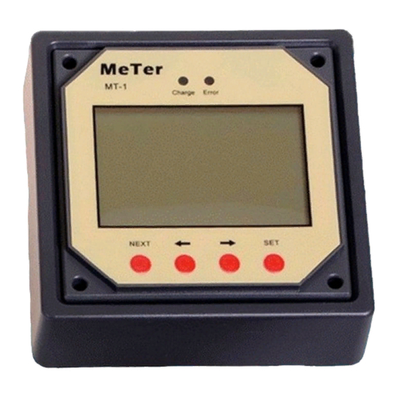
Page 4: Identification Of Display
Identification of Display 1. Solar Icon 2. Battery Icon(s)—icon is present if the battery is connected otherwise it will remain flashing. It will demonstrate the battery level in which each bar represents 20% of the battery capacity. 3. Remote Temperature Sensor Icon (optional)—if the charge controller has the Remote Temperature Sensor connected (separate purchase required), the meter will display this icon. -
Page 5: Installation
Resolve any issues before installing the meter and the meter cable. The MT-1 can be mounted in two ways: Frame Mount or in a Wall Mount. A plastic mounting frame has been included for the purpose of Frame Mounting. If Wall Mounting then the MT-1 faceplate sits flush with the mounting surface and the body of the meter would be able to rest comfortably in a hole cut-out on the mounting surface. -
Page 6: User Parameter Setting
The user can also use the (K2) (), (K3) () keys to cycle within the four menus and display more information Data Screens PV Solar Battery 1 and Battery 2 Temperature / Time 1. Solar Panel Volts (V) 1. Battery Voltage (V) 1. - Page 7 icon will be displayed when the user is in the SET function. It will disappear once the user is in the reading menu. Function Display Description Temperature Changes Temperature Units (C°) to (F°) Backlight Sets a backlight timer after last button push On: Always on B:30 –...
-
Page 8: System Status Icons And Considerations
Both batteries must be connected to the charge controller, otherwise there will be a default error. Telecommunication Port When the meter running on individual power or the communication is cut off, the MT-1 will display graphical symbols abnormally. Press any key to stop the display and resume normal... -
Page 9: Battery Level Flashing
Make sure that the MT-1 is not in half-brightness mode. Check the system battery voltage. The MT-1 needs a minimum of 8 V to operate. Verify that the temperature is within range of the LCD operating parameters. -
Page 10: Technical Specifications
110 x 110mm (4.33 x 4.33in) Temperature Parameters Operation Temperature -40°F to 140°F LCD Operation Temperature -14°F to 104°F Humidity 0-100% CAD Dimensions NOTE: Dimensions are in millimeters (inches) Renogy reserves the right to change the contents of this manual without notice. Revision: 9/14/2017...
Need help?
Do you have a question about the MT-1 and is the answer not in the manual?
Questions and answers