Table of Contents
Advertisement
Quick Links
Advertisement
Table of Contents

Related Manuals for Renogy RMS-DCDC-US


Summary of Contents for Renogy RMS-DCDC-US
- Page 1 MONITORING SCREEN FOR DC-DC BATTERY CHARGER SERIES Version 1.0 RMS-DCDC...
-
Page 2: Important Safety Instructions
Important Safety Instructions Please save these instructions. This manual contains important installation and operation instructions for the monitoring screen. Please observe these instructions and keep them located near the monitoring screen for further reference. The following symbols are used throughout the manual to indicate potentially dangerous conditions or important safety information. -
Page 3: Table Of Contents
Table of Contents Important Safety Instructions General Information Product Overview Identification of Parts Dimensions Installation Operation LCD Icons LCD Menu Overview Voltage Interface Kilowatt Interface Current Interface Temperature Interface Working Mode Parameter Setting Set the Battery Type Clear KWh to 0 Set Current Limiting Change from Celsius to Fahrenheit Troubleshooting... -
Page 4: General Information
General Information The RMS-DCDC is a high precision meter designed for DC-DC MPPT Series on board battery chargers. Featuring a backlit display and flush-mountable, it is engineered for an aesthetically clean and professional look inside vehicle cabins. Utilize the 4-key input to navigate through the backlit LCD for system information, configure charging parameters, as well as identify any error codes. -
Page 5: Product Overview
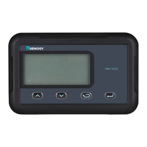
Product Overview Identification of Parts RMS-DCDC ① ② ③ ④ ⑤ ⑧ ⑦ ⑥ LCD Screen Enter ① ⑤ Page Up Front Cover Plate ⑥ ② Page Down Mounting Holes ③ ⑦ Previous Page RJ45 Communication Port ⑧ ④... -
Page 6: Dimensions
Dimensions 110.0mm 4.3in RMS-DCDC 87.5mm 3.4in 31.5mm 1.24in 19.9mm 0.8in Dimensions have a tolerance of ±0.5mm NOTE... - Page 7 Additional Components RJ45 Communication Cable The RJ45 Communication Cable (5m/16.4ft) is used to connect the monitoring screen to t power supply and data transmission. NOTE You may use ethernet cables CAT5 or higher. Self-tapping Screws (4) The Self-tapping Screws (M2.9x13) are used fix the monitoring screen on the mounting surface.
-
Page 8: Installation
Installation WARNING Before drilling, make sure there are no electrical component or other obstacles that may interfere with installation on the other side of the mounting surface. CAUTION Before installation, check to make sure the power is working properly. Resolve any issues before installation of monitoring screen and cable. - Page 9 Mounting the Monitoring Screen 1. Remove the snap-fit Front Cover Plate from the monitoring screen. 2. Use the monitoring screen as a template to mark the screw holes and trace the cut-out area on the mounting surface with a pencil. 3.
- Page 11 19.9mm 0.78in 87.5mm 3.44in Cutout Dimensions (L x H x W): 87.5 x 58.0 x 19.9mm (3.44 x 2.28 x 0.78in)
- Page 13 Connecting to the DCDC Utilize the included RJ45 communication cable to connect between the DC-DC MPPT RS485 Port and the back of the RMS-DCDC. RJ45 Communication cable...
-
Page 14: Operation
Operation Use the following keys to navigate through the monitoring screen Meaning Page Up Page Down Previous Page Exit Parameter Setting Mode Enter—Tap to Enter Parameter Setting Key—Hold for approximately 2~3 seconds to enter parameter setting mode... -
Page 15: Lcd Icons
LCD Icons 1. System Voltage The 12V system voltage will be illuminated while the RMS-DC- DC is powered on or during operation. 2. State of charge Whether charging with PV, Alternator, or PV + Alternator, the charge state will reflect either MPPT, BOOST, FLOAT. Only batteries with an equalization charge will see EQUALIZE.In addition, Lithium batteries will display MPPT and Boost only. - Page 16 4. Solar Charging Icon Indicates solar is charging the house battery. Solar will take priority over alternator charging. 5. House Battery Icon When “H” is shown with parameters, it refers to the house battery parameters. 6. Parameter Units Total Charging Amps (A), Instant Kilowatt (KWH), Voltage (V), and Temperature (◦C or ◦F).
-
Page 17: Lcd Menu Overview
8. House Battery SOC Icon Indicates the estimated state of charge of the house battery. State of charge is voltage based and will be split into 4 bars each representing 25% increments for a total of 100%. Factors such as temperature, charge, and discharge can affect the state of charge. -
Page 18: Voltage Interface
Voltage Interface The top line displays the house battery (DC Output) voltage as well as a graphical display of the battery using voltage-based SOC. Each bar represents 25% for a total of 100%. The bottom line shows the starter battery (DC Input) voltage. -
Page 19: Working Mode
Working Mode Once the RMS-DCDC is on, it will display different pages depending on the sources connected. PV Charing Mode will take priority when charging the house or starter batteries. House battery information will appear on the top line and starter battery information in the bottom line. Only PV Charging—Starter Battery &... - Page 20 4.When and if PV charges both the house battery and starter battery at the same time, there will be a solar icon above the H and S. Only ALT Charging—Starter Battery & House Battery Connected 1.ALT charging will follow this chart, depending on your alternator type.
- Page 21 4.When no current is detected going to the House Battery, the ALT charging arrow will disappear. PV + ALT Charging—Starter Battery & House Battery Connected 1.PV charging will be maximized before supplementing any power with ALT charging. If PV charging alone is enough to charge the house battery, then the ALT circuit will not charge the house battery.
-
Page 22: Parameter Setting
3.Charging of both starter and house battery at the same time will be indicative of solar icon over the S and the ALT charging arrow. Parameter Setting Set the Battery Type You can change the battery type to confirm the preselected battery profiles for Gel, Flooded, Sealed, Lithium, or a User Setting. - Page 23 2.Use Up/Down keys to highlight battery 1.Hold the Param. Setting key for 2-3s until flashing Voltage Interface 3.Confirm battery by holding Param. Setting key for 2-3s 4.Confirm setting by holding Param. Setting key for 2-3s...
- Page 24 Setting Lithium 1. Use the Page Up/Down key to show the Voltage Interface. Hold down Parameter Setting Key for approximately 2-3seconds and the top line will begin flashing the battery type. 2. Use the Page Up/Down to highlight Li (Lithium). 3.
- Page 25 Setting User 1. Use the Page Up/Down keys to show the Voltage Interface. Hold down Parameter Setting Key for approximately 2-3seconds and the top line will begin flashing the battery type. 2. Use the Page Up/Down to highlight User (USE). 3.
- Page 26 2.Use Up/Down keys to 1.Hold the Param. Setting highlight “USE” then Tap key for 2-3s until flashing Param. Setting key 3.Use Up/Down keys to highlight boost voltage, then Tap Param Setting key 5.Use Up/Down keys to highlight equalization voltage, then 4.Use Up/Down keys to Tap Param Setting key highlight float voltage, then...
-
Page 27: Clear Kwh To 0
Clear KWh to 0 The kilowatt hour generation will automatically store historical information. To clear the values to 0: 1. Use the Page Up/Down keys to show the Kilowatts Interface. Hold down Parameter Setting Key for approximately 2-3seconds and the bottom line will begin flashing 2. - Page 28 To get started: 1. Use the Page Up/Down keys to show the Current Interface. Hold down Parameter Setting Key for approximately 2-3seconds and the top line will begin flashing rated current rating 2. Use the Page Down to highlight your desired current limit rating 3.To confiem,hold down the Parameter Setting Key for approximate- ly 2-3seconds.
-
Page 29: Change From Celsius To Fahrenheit
Change from Celsius to Fahrenheit The default temperature is Celsius. If the RMS-DCDC is restarted, then it will refer to the default setting. Change from Celsius to Fahrenheit or vice versa: 1. Use the Page Up/Down keys to show the Temperature Interface. Hold down Parameter Setting Key for approximately 2-3seconds and the top and bottom lines will flash. -
Page 30: Troubleshooting
Troubleshooting The RMS-DCDC provides you with a visual for what is occurring in the system. When the RMS-DCDC is not operating correctly, then you will need a multi-meter to validate some of the troubleshooting steps. Problem-Solution Make sure you are using the provided cable or that it is a CAT5 or higher if using your own Firmly press the ethernet jack onto the back port on the RMS-DCDC until you hear aclicking... - Page 31 The warning is letting you know that you’re using more than your battery can supply. House It is recommended to limit your load use to not Battery Low run the battery to empty Voltage It is also recommended to connect a charging source, Warning solar or alternator, to slow down the battery draining.
- Page 32 1. Disconnect the starter battery from the circuit Alternator 2. Double check the alternator voltage does not Over-voltage exceed 16.5V. Protection 1. Disconnect the starter battery from the circuit Alternator 2. Check on the alternator charging rating to Overcurrent ensure not over the 30A|50A limit. The panel is producing voltage higher than the 25V operating voltage of the DC-DC MPPT.
-
Page 33: Technical Specifications
Technical Specifications Electrical Specifications Supply Voltage 5VDC Supply Current 30mA Power Consumption <1W Operating Temperature Range -4℉~113℉ / -20℃~45℃ Voltage Accuracy ±0.1V Current Accuracy ±0.1A Mechanical Specifications Communication Port RJ45 (RS485 Protocol) Display Backlit LCD User Interface 2key input, 1main power switch Mounting System Wall Mount 2.8 x 4.3 x 1.24 inch... - Page 34 Battery Charging Chart Battery Custom SLD/ USER Type Range (LFP) (Default) Parameters (USER/LI) Over- voltage Warning Charging Limit 15.5V 15.5V 15.5V 15.5V 15.5V Voltage Over- voltage Recover Boost 14.4V 14.6V 13.2V- Charge 14.6V 14.2V 14.6V 15.5V (adjustable) (adjustable) Voltage Float 13.8V 13.2V- Charge...
- Page 35 NOTE User Mode is an extra feature accessed via App Development Only or Monitoring Screen. However, Boost Duration, Equaliza- tion Interval, and Equalization Duration can only be programmed through App Development. The battery charging parameters assume conditions to be 77℉ / 25℃...
- Page 36 RENOGY.COM Renogy reserves the right to change the contents of this manual without notice. 2775 E Philadelphia St, Ontario, CA 91761, USA 909-287-7111 www.renogy.com support@renogy.com 苏州高新区科技城培源路1号5号楼-4 400-6636-695 https://www.renogy.cn support@renogy.cn https://www.renogy.jp supportjp@renogy.com https://ca.renogy.com supportca@renogy.com https://au.renogy.com supportau@renogy.com https://uk.renogy.com supportuk@renogy.com https://de.renogy.com supportde@renogy.com...
Need help?
Do you have a question about the RMS-DCDC-US and is the answer not in the manual?
Questions and answers