Table of Contents
Advertisement
Quick Links
Advertisement
Table of Contents

Related Manuals for Renogy RMS-RVRE


Summary of Contents for Renogy RMS-RVRE
- Page 1 MONITORING SCREEN FOR ROVER ELITE SERIES Version 1.1...
-
Page 2: Important Safety Instructions
Important Safety Instructions Please save these instructions. This manual contains important installation and operation instructions for the monitoring screen. Please observe these instructions and keep them located near the monitoring screen for further reference. The following symbols are used throughout the manual to indicate potentially dangerous conditions or important safety information. - Page 3 DO NOT puncture, drop, crush, burn, penetrate, or strike the monitoring screen. DO NOT open, dismantle, or modify the monitoring screen. The monitoring Screen is only compatible with Renogy Elite Series charge controllers. DO NOT attempt connecting the monitoring screen to other charge controllers or systems.
-
Page 4: Table Of Contents
Table of Contents Important Safety Instructions General Information Product Overview Identification of Parts Dimensions Installation Operation LCD interface Navigating through Screens LCD Indicators Programming Battery Type Selecting Lithium Lithium Battery Activation Troubleshooting Technical Specifications... -
Page 5: General Information
General Information The RMS-RVRE is a high precision meter designed for Rover Elite charge controllers. Featuring a backlit display and flush-mountable, it is engineered for an aesthetically clean and professional look on RVs or camper walls. Utilize the 4-key input to easily navigate through your system information or modify quick parameters as well as identify any error codes. -
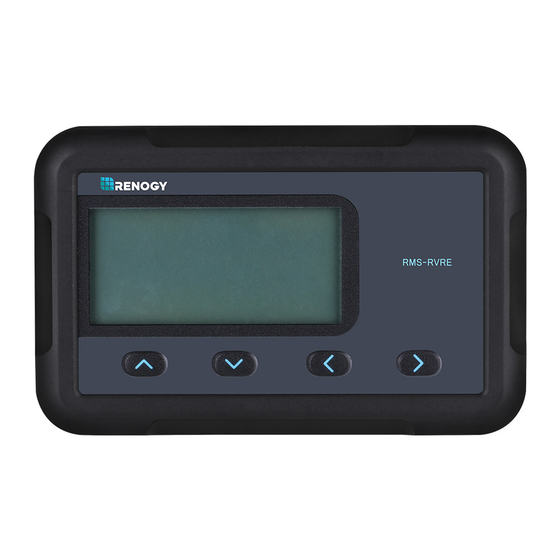
Page 6: Product Overview
Product Overview Identification of Parts RMS-RVRE ① ② ③ ④ ⑤ ⑥ ⑦ ⑧ LCD Screen Parameter Setting Button ① ⑤ Page Forward Button Front Cover Plate ⑥ ② Page Backward Button Mounting Holes Locations ③ ⑦ Previous Page Button RJ45 Communication Port ⑧... -
Page 7: Dimensions
Dimensions 110.3mm 31.5mm 4.34in 1.24in RMS-RVRE 19.9mm 0.8in Additional Components RJ45 Communication Cable The RJ45 Communication Cable (5m/16.4ft) is used to connect the monitoring screen to the charge controller for power supply and data transmission. Self-tapping Screws (4) The Self-tapping Screws (M2.9x13) are used affix the monitoring... -
Page 8: Installation
Resolve any issues before installation of monitoring screen and cable. The RMS-RVRE requires a flush mount installation. The RMS-RVRE’s faceplate will be flush with the mounting surface and the body of the meter. Preparation Before the installation of the monitoring screen, it is recommended... - Page 9 Mounting the Monitoring Screen 1. Remove the snap-fit Front Cover Plate from the monitoring screen. 2. Use the monitoring screen as a template to mark the screw holes and trace the cut-out area on the mounting surface with a pencil. 3.
- Page 10 Cutout Dimensions (L x H x W): 86.7 x 58.02 x 19.8mm (3.41 x 2.28 x 0.78 inch) 19.8mm 86.7mm...
-
Page 13: Operation
Connecting to the Charge Controller Please connect the monitoring screen to the RS485 Port of the Rover Elite using the included RJ45 Communication Cable. RJ45 RJ45 Communication Port Communication Cable RJ45 Communication Port Operation LCD interface: solar panel charging battery abnormality charging stage... -
Page 14: Navigating Through Screens
The RMS-RVRE is ONLY compatible with Rover NOTE Elite Series charge controllers. The following keys are used to navigate through system, PV, and battery information as well as identifying any error codes. Us the up and down keys to navigate through the monitoring screens. -
Page 15: Lcd Indicators
LCD Indicators Icon or Value State Description Steady on Solar Panels Charging Battery 3 Bars Flashing Battery Voltage (16.1V+) 3 Bars Battery Voltage (12.9V- 16.0V) Battery Voltage (12.5-12.8V) 2 Bars 1 Bar Battery Voltage (11.6-12.4V) No Bars Battery Voltage ( 11.5V and below No Bars Flashing Battery Voltage (... -
Page 16: Programming Battery Type
Battery Voltage Battery Voltage is displayed indicated by Batt. System voltage is also displayed. BATT Accumulated AH Accumulated consumption is displayed. You may clear the contents back to 0 through the controller. temperature displayed Ambient Temperature controller’s or the remote temperature sensor if utilizing the accessory. - Page 17 To enter battery programming settings, navigate to the Battery Voltage Screen (below) and then press and hold the right key button until the screen starts to flash the battery type: BATT Press and Hold Battery Type BATT BATT BATT BATT BATT Utilize the arrows to navigate through Sealed Lead Acid / AGM (SEL), Lithium-Iron Phosphate...
-
Page 18: Selecting Lithium
Selecting Lithium Incorrect battery type setting may damage your WARNING battery. Please check with your battery manufacturer’s specifications before selecting the battery type. If selecting Lithium, Lithium refers to Lithium NOTE iron-phosphate and you will need to manually set the voltage to 12V or 24V as well as choose your charging voltage (14.4V Boost Voltage by default). -
Page 19: Lithium Battery Activation
NOTE is only available batteries. other battery types, the RMS-RVRE will recognize the Rover’s Elite’s auto recognition system voltage and adjust accordingly. Set Li Boost Voltage: By default, the boost voltage will be 14.4V for Li. Once in the Boost Voltage screen, you can navigate in increments of 0.2V to set your appropriate boost voltage. -
Page 20: Troubleshooting
Troubleshooting Error Codes / Troubleshooting If the Rover Elite is not functioning properly, it will display an error code not normally seen in the interface display. Depending on the code, you may attempt to troubleshoot the error to commence normal system operation. Error Meaning Troubleshoot... - Page 21 Record the ambient temperature found in the controller screen. Make sure the controller is not placed in direct line of Controller is heating sources or that it is over-heating over- due to over-sun exposure. The controller temperature will resume normal operation upon cooling down.
- Page 22 Behavior Protective Function / Fixes Reverse Battery Polarity Protection The Rover Elite needs a correct battery connection to startup. This might mean that The battery is the battery cables are reversed. Use a connected to multi-meter to make sure your voltage reading thecontroller, has the correct polarity (Red to positive and but the...
- Page 23 E02 Battery Overcharging If the battery was charging fine and stopped, it could be because it was being overcharged by the solar source if not an external source. My system You might see an E02 display or perhaps an stopped empty screen.
- Page 24 Maintenance For best controller performance, it is recommended that these tasks be performed from time to time. 1.Check wiring going into the charge controller and make sure there is no wire damage or wear. 2.Tighten all terminals and inspect any loose, broken, or burnt up connections.
-
Page 25: Technical Specifications
Technical Specifications Electrical Specifications Supply Voltage 5VDC Supply Current 30mA Power Consumption <1W Operating Temperature Range -4℉~113℉/ -20℃~ 45℃ Voltage Accuracy ±0.1V Current Accuracy ±0.1A Mechanical Specifications Communication Port RJ45 (RS485 Protocol) Display Backlit LCD User Interface 4 Front Panel Menu Buttons Mounting System Wall Mount 2.8 x 4.3 x 1.3 inch /... - Page 26 Battery Charging Parameters Battery SLD/AGM FLOODED LI(LFP) High Voltage 16 V 16 V 16 V 16 V Disconnect Over Voltage 15 V 15 V 15 V 15 V Reconnect Equalization ----- ----- 14.8V ----- Voltage 14.4V Boost Charge 14.6 V 14.2 V 14.6 V User:...
- Page 27 This equipment has been tested and found to comply with the limits for a class B digital device, pursuant to part 15 of the FCC Rules. These limits are designed to provide reasonable protection against harmful interference in a residential installation.
- Page 28 RENOGY.COM Renogy reserves the right to change the contents of this manual without notice. 2775 E Philadelphia St, Ontario, CA 91761, USA 909-287-7111 www.renogy.com support@renogy.com 苏州高新区科技城培源路1号5号楼-4 400-6636-695 https://www.renogy.cn support@renogy.cn https://www.renogy.jp supportjp@renogy.com https://ca.renogy.com supportca@renogy.com https://au.renogy.com supportau@renogy.com https://uk.renogy.com supportuk@renogy.com https://de.renogy.com supportde@renogy.com...
Need help?
Do you have a question about the RMS-RVRE and is the answer not in the manual?
Questions and answers