Table of Contents
Advertisement
Quick Links
Technical Support and E-Warranty Certificate www.vevor.com/support
GAS HEDGE TRIMMER
USER MANUAL
We continue to be committed to provide you tools with competitive price.
"Save Half","Half Price" or any other similar expressions used by us only represents an
estimate of savings you might benefit from buying certain tools with us compared to the major
top brands and does not necessarily mean to cover all categories of tools offered by us. You
are kindly reminded to verify carefully when you are placing an order with us if you are
actually saving half in comparison with the top major brands.
Advertisement
Table of Contents

Subscribe to Our Youtube Channel
Related Manuals for VEVOR F26-B


Summary of Contents for VEVOR F26-B
- Page 1 Technical Support and E-Warranty Certificate www.vevor.com/support GAS HEDGE TRIMMER USER MANUAL We continue to be committed to provide you tools with competitive price. "Save Half","Half Price" or any other similar expressions used by us only represents an estimate of savings you might benefit from buying certain tools with us compared to the major top brands and does not necessarily mean to cover all categories of tools offered by us.
- Page 2 This is the original instruction,please read all manual instructions carefully before operating. VEVOR reserves a clear interpretation of our user manual. The appearance of the product shall be subject to the product you received. Please forgive us that we won't inform you again if there...
- Page 3 IMPORTANT READ CAREFULLY BEFORE USE. KEEP FOR FUTURE REFERENCE. Training 1. Read the instructions carefully. Be familiar with the controls and the proper use of the product. 2. Never allow children or people unfamiliar with these instructions to use the product. Local regulations can restrict the age of the operator. 3.
-
Page 4: Operation
safety glasses is recommended. 4. Store the product in a dry, clean place protected from direct sunlight only after the fuel tank has been emptied and the product is cleaned. The product must be stored inside only under these conditions. 5. - Page 5 10.Only use the product in daylight or good artificial light. 11.Keep your body upright during operation. Do not lean forward. Make regular breaks and change your working position to stay concentrated. 12.Keep firm footing and balance during operation. Always use the harness, if provided.
- Page 6 Maintenance and storage 1. Follow the maintenance and repair instructions for this product. Never carry out any modifications to the product. 2. When the product is stopped for servicing, inspection or storage, shut off the power source, disconnect the spark plug connector from the spark plug and make sure all moving parts have come to a stop.
- Page 7 Additional safety warnings for pole saw 1. Interrupt your work when you feel tired. Make regular breaks to regenerate. A moment of inattention while operating the product may result in serious personal injury. 2. Keep all parts of the body away from the saw chain. Do not remove cut material or hold material to be cut when saw chain is moving.
-
Page 8: Causes And Operator Prevention Of Kickback
off balance. 11.Carry the product by the handles/poles with the product switched off and away from your body. When transporting or storing the product always fit the guide bar cover. Proper handling of the product will reduce the likelihood of accidental contact with the moving saw chain. 12.Follow instructions for lubricating, chain tensioning and changing accessories. - Page 9 object, or when the wood closes in and pinches the saw chain in the cut. • Tip contact in some cases may cause a sudden reverse reaction, kicking the guide bar up and back toward the operator. • Pinching the saw chain along the top of the guide bar may push the guide bar rapidly back towards the operator.
-
Page 10: Fuel Handling
When transporting or storing the hedge trimmer always fit the cutting device cover. Proper handling of the hedge trimmer will reduce possible personal injury from the cutter blades. 3. Hold the product by insulated gripping surfaces only, because the cutter blade may contact hidden wiring. - Page 11 8. Close the tank lid immediately after filling the tank. Make sure that it is properly closed. 9. Never use the product without an air filter. 10.Fuel vapour pressure may build up inside the fuel tank depending on the fuel used, weather conditions and the tank venting system. To reduce the risk of burns and other personal injuries, remove the fuel cap carefully to allow any pressure build up to release slowly.
- Page 12 operation, use low-vibration and low-noise operating modes as well as wear personal protective equipment. Take the following points into account to minimize the vibration and noise exposure risks: 1. Only use the product as intended by its design and these instructions. 2.
-
Page 13: Residual Risks
Emergency Familiarise yourself with the use of this product by means of this instruction manual. Memorize the safety directions and follow them to the letter. This will help to prevent risks and hazards. 1. Always be alert when using this product, so that you can recognize and handle risks early. - Page 14 objects. 4. Burns, if touching hot surfaces. 5. Kickback. Symbols On the product, the rating label and within these instructions you will find among others the following symbols and abbreviations. Familiarise yourself with them to reduce hazards like personal injuries and damage to property.
- Page 15 2-stroke motor oil: ISO-L-EGD/JASO FD Open flames and smoking in the vicinity of the appliance are strictly prohibited! Guaranteed sound power level of the appliance Cutting device continues to rotate after the product is switched off. Wait until all components have completely stopped before touching the product.
- Page 16 arm or leg. Always keep people and animals at least 15 metres from the product. Caution! Poisonous CO vapours (carbon monoxide vapours)! Do not use the appliance in closed rooms! WARNING! Hair can be sucked into the appliance! Caution – petrol is highly flammable! Explosion hazard! Do not spill any fuel! Turn the appliance off and remove the spark plug connector before performing any maintenance work!
-
Page 17: Part List
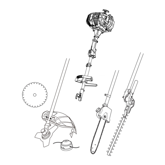
PART LIST... - Page 18 Main unit Engine Rope Air vents Securing clip Muffler Upper pole Recoil starter handle Suspense sleeve (x1) Fuel tank Locking sleeve Fuel tank cap Locking knob Primer Spring bolt Air filter case Bracket Fixation bolt Bolt (x 2) Cover Nut (x 2) Filter Front handle Choke...
- Page 19 Brush cutter / grass trimmer Lower pole Cutter blade (three teeth) Bracket Locking flange Washer (x 2) Spring washer (x 2) Cutter blade (forty teeth) Bolt (x 2) Trimming head Knife Cover Knife cover Spool Guard Trimming line Guard extension Spring Latch (x 3) Housing...
- Page 20 Pole saw Lower pole Tension screw Cover Oil tank Retaining nut Oil tank cap Drive sprocket Saw chain Oiling port Guide bar Bolt Lubrication hole Adjustment screw (chain oil Sprocket wheel flow) Tension pin Guide bar cover...
- Page 21 Pole hedge trimmer Lower pole Teeth system Handle Support Cutting blade Bolt (x 2) Blade cover (x 2) Spring washer (x 2) Unlock lever (x 2) Washer (x 2)
- Page 22 Tools Fuel mixing container Assembly wrench Multi tool Hex key (5 mm) Funnel Hex key (4 mm) Protective earmuffs Screw *4 Nut*4 goggles Face shields Tote bag Glove...
- Page 23 Unpacking 1.Unpack all parts and lay them on a flat, stable surface. 2.Remove all packing materials and shipping devices if applicable. 3.Make sure the delivery contents are complete and free of any damage. If you find that parts are missing or show damage do not use the product but contact your dealer.
-
Page 24: Front Handle
Assembly Front handle 1. Remove the pre-assembled bolt (A25) and nut (A26) from the handle bracket (A24) and keep them handy (Fig. 1). 2. Insert the shaft end of the front handle(A 27) into the bracket opening.Adjust the front handle with a twist motion to align the mounting holes. 3. - Page 25 Pole assembly 1. Choose the desired tool attachment according to the intended operation. 2. Remove the pre-attached protection cap from the lower pole(B1/ C1/D1) (Fig.3,step 1) . 3. Loosen the locking knob(A 22),but don’t fully remove e(Fig.3,step 2). 4. Align and insert the lower pole(B 1/C 1/D 1) into the locking sleeve (A 21) , while pulling the spring bolt(A 23) (Fig.3,step 3 and 4) .
-
Page 26: Cutting Options
3) Secure the connection with bolts (B5),spring washers rs( (B4) ) and washers (B3) ) using the tool(E4) .(Fig.4). 2. Cutting options Assemble the relevant cutting attachment to suit the intended operation. NOTE:The thread on the spindle is left-hand.Turn clockwise to remove and turn anticlockwise to secure respective cutting attachment. - Page 27 6) Place the locking flange (B15) onto the cutter blade (B14). 7) Tighten the nut (B16) to secure the cutter blade counterclockwise while locking the spindle (B12) with the hex key (E5). Remove the hex key afterward (Fig. 5). 4.Trimming head 1) Rotate the backing flange (B13) until its hole is aligned with the hole on the gear head (B11).
- Page 28 Pole saw WARNING! Always wear gloves during assembly! Assemble the guide bar (C13) and saw chain (C12) before operation. 1. Chain and guide bar assembly 1) Use only a guide bar (C13) and saw chain (C12) according to the technical data of the pole saw.
- Page 29 4) Spread the saw chain (C12) out with the cutting edges of the chain pointing in the direction of rotation. Slide the saw chain (C12) into the groove around the guide bar (C13). Ensure saw chain (C12) is installed in correct direction of rotation. (Fig.8) WARNING! The direction of the saw chain ‘cutters’...
- Page 30 6) Align saw chain (C12) and the guide bar (C13) assembly with the drive sprocket (C4) and the mounting bolt (C6). Lay the saw chain (C12) around the drive sprocket (C4) and then lower the guide bar (C13) to install it to the mounting bolt (C6).
- Page 31 Make sure the saw chain (C12) is properly placed over the sprocket wheel (C15) of the guide bar (C13). (Fig.11) 8) Refit the cover (C2), fit the rear of cover then front, ensure pin is located in position. Slightly tighten the remaining nut (C3) by using the assembly wrench (E3) (Fig.
-
Page 32: Saw Chain Tensioning
2.Saw chain tensioning Always check the saw chain tension before use, after first cuts and regularly during use, approx. every five cuts. After initial operation, new chains can lengthen considerably. This is normal during the break-in period and the interval between future adjustments will lengthen quickly. -
Page 33: Tension Test
3) Screw the tension screw (C9) clockwise or unti-clockwise to adjust the tension pin (C8) / guide bar (C13) until the chain ‘tie straps’ are just touching the bottom edge of the guide bar (Fig. 14). 3.Tension test 1) Check the chain tension using one hand to lift the saw chain (C12) against the weight of the product. -
Page 34: Chain Lubrication
4.Chain lubrication WARNING! The product is not filled with oil. It is essential to fill the product with oil before using it! Never operate the product without chain oil or with an empty oil tank, as this will result in extensive damage to the product! Never operate the bar and chain without lubrication oil! Operating the product dry or with too little oil will decrease cutting efficiency, shorten the product life span and cause rapid wear to the chain and bar from overheating! Insufficient oil is... - Page 35 4) Wipe up spilled lubricant with a soft cloth and refit the oil tank cap (C11). NOTE: Always dispose of lubricant, used oil and objects contaminated with them in accordance with local regulations. 5) Check the oil level prior to start-up and regularly during operation 5.Checking NOTE: Perform the following test before operating your product.
-
Page 36: Pole Hedge Trimmer
4) Turn the adjustment screw (C7) of the oiler on the bottom of the product to adjust the chain oil flow with the multi tool (E2) (Fig. 19). Pole hedge trimmer 1.Blade head 1) Loosen the bolts (D8) using tool (E5) until the lower pole (D1) can be inserted into the support (D7) (Fig. - Page 37 4) Hold the handle (D2) with left hand and the lower pole (D1) with the right hand. 5) Press the unlock levers (D5) to disengage the teeth system (D6) and adjust the blade head to the desired position (Fig. 21). 6) Release the unlock levers (D5) afterward.
-
Page 38: Fuel And Engine Oil
WARNING! The blade head can be adjusted in 12 different positions. Always ensure the teeth system is securely engaged! Do not attempt to use the product with the blade head in any intermediate position with the teeth system disengaged! 2.Blade cover 1) Remove the blade covers (D4) from the blade (D3) before operation (Fig. - Page 39 1. Place the product on a stable, level surface. We recommend laying a non-flammable sheet under the product. 2. Avoid spilling and overfilling the tanks. WARNING! Fuel and oil are highly inflammable! Fumes will explode if lit! Ensure that there are no naked flames around the product! Do not smoke while filling fuel and oil! 3.
- Page 40 NOTE: Never mix fuel and oil directly in the tank of the product. Use a fuel mixing container that helps to ensure the correct mixing ratio. Shake gently to ensure a thorough mix of fuel and oil. 5. Always use clean, fresh unleaded petrol. Purchase fuel in quantities that can be used within 30 days.
-
Page 41: Operating Controls
Operating controls... - Page 42 Cold start Warm start...
- Page 43 Stopping Storage WARNING! This quick start provides only a short overview of how to start and stop the product! For safe use it is essential to read the entire instruction manual before first use!
-
Page 44: Intended Use
Intended use This petrol tool 4 in 1 FP4MTP33 is designated with a rated output of 1 kW. The product is multifunctional and can be used as brush cutter, grass trimmer, pole saw and pole hedge trimmer according to the intended operation with desired tool attachment. -
Page 45: Product Functions
Product functions Primer The primer (A7) is positioned underneath the air filter case (A8). Use the primer for cold start (Fig. 27). Recoil starter 1. The recoil starter handle (A4) is positioned at the rear side of the engine. 2. Hold the product stable and pull the recoil starter handle lightly until you feel resistance then pull it rapidly. - Page 46 WARNING! Never twist the starter rope around your hand! Only pull on the handle! WARNING! Do not suddenly release the recoil starter handle! Allow the rope to return slowly and in a controlled manner each time it is pulled! Do not pull out the recoil starter beyond the red colour band at the end of the recoil starter! Pulling excessively will cause damage on the recoil starter cord.
-
Page 47: Control Unit
Control unit There are three controls on the main handle (A31) with the following functions (Fig. 31): 1. The throttle interlock (A30) prevents unintentional activation of the throttle trigger (A29). 2. The ignition switch (A28) electrically starts or stops the engine. 3. - Page 48 2. Place the harness (A16) so that it runs over the left shoulder, crossing the chest and back. The securing clip (A18) must be located at the right hip (Fig. 33). 3. Ensure the position of the product is properly balanced. 4.
- Page 49 Handle adjustment 1. Loosen the bolts (A25) and nuts (A26). Do not remove the bolts and nuts from the bracket (A24). 2. Slide the bracket (A24) up or downward to one of the three positions until the mounting holes are aligned (Fig. 35). 3.
- Page 50 WARNING! The cut line will be thrown out! Danger of injury especially for bystanders! Guard extension (for brush cutter and grass trimmer) The guard (B8) and guard extension (B9) protects the operator against thrown objects during operation. It is equipped with a knife (B6) that cuts the trimming line (B21) (Fig.
- Page 51 Operation instructions General 1. Check the product as well as accessories for damage before each use. Do not use the product if it is damaged or shows wear. 2. Double check that the accessories and attachments are properly fixed. 3. Check the fuel level, refill if necessary. 4.
- Page 52 5. Hold the product stable and pull the recoil starter handle (A4) slowly until you feel resistance then pull it rapidly. Move the choke slight downward to middle position if the engine does not start after trying up to 8 times. Do it again until the engine starts (Fig.
-
Page 53: Warm Start
8. Once the engine is running smoothly, carefully lift the product and secure it to the harness (A16) by way of the securing clip (A18). 9. Firmly hold the product with left hand on front handle (A27) and right hand on main handle (A31). - Page 54 WARNING! Allow the rope to return slowly and in a controlled manner after each pull! WARNING! The cutting attachment should not move during idling speed! If you find that the cutting attachment is moving, stop using the product and have it inspected and adjusted by an authorised service centre or a similarly qualified person! 6.
- Page 55 Stopping 1. Release the throttle interlock (A30) and throttle trigger (A29) and let the product run at its idle speed for 10 – 15 seconds. 2. Set the ignition switch (A28) to position “STOP” (Fig. 42). 3. Carefully put down the product. Cutting (brush cutter) 1.
- Page 56 Kickback (blade thrust) is more likely to occur in areas where it is difficult to see the material to be cut! Danger zone between 12 and 2 o ’ clock 2. Hold the product firmly so that it sits with a gap between the product and your right side.
- Page 57 6. Ensure the cutting device remains clean and free from off-cuts that may cause it to jam. Check regularly. Stop the engine, set the ignition switch (A28) to “STOP” and remove the spark plug connector (A13) before checking. 7. Trim longer grass in stages; do not cut long grass in one cut (Fig. 46). For the best results, cut longer grass in steps (Fig.
- Page 58 NOTE: The trimming line will wear faster and require more feeding if cutting is done along sidewalks or other abrasive surfaces or heavier weeds are being cut. While trimming, the cutting device is possible to be blocked by grass or unevenly ground.
- Page 59 1. Kickback is the sudden backward/upward motion of the product, occurring when the chain (at the tip of the chain bar) comes in contact with a log or wood, or when the chain becomes jammed. 2. When kickback occurs the product reacts unpredictably and can cause severe injuries to the operator or bystanders.
- Page 60 4. Never stand directly under the limb you are sawing. Objects may fall different than expected. Always position yourself out of the path of falling limps (Fig. 51). 5.Keep other persons away from cutting end of product and at a safe distance from the work area.
- Page 61 product! When pruning trees, it is important not to make the flush cut next to main limb or trunk until you have cut off the limb further out to reduce the weight! This prevents stripping the bark from the main member! 6.
- Page 62 NOTE: The chain must be running at full speed before it comes into contact with the wood. Thin branches Thin branches can be cut off with one single cut. To prevent the branch from slivering and buckling the branch should be cut off in several pieces (Fig. 55). Thick branches When cutting off larger branches three cuts are necessary.
- Page 63 Trimming Trimming times green leaf hedges June to October evergreens April and August conifers and other fast growing shrubs every 6 - 8 weeks 1. Adjust the blade head to the required position as described above. 2. Cut and remove branches exceeding the cutting capacity of this product using a proper pole saw before operation.
- Page 64 7. Move the product with slow motion forward when cutting higher hedge and the cutting area out of sight (Fig. 61). 8. Do not rush and do not attempt to cut too much with one stroke of the cutting blade. 9.
-
Page 65: General Cleaning
The golden rules for care WARNING! Always switch the product off, disconnect the spark plug connector and let the product cool down before performing inspection, maintenance and cleaning work! 1. Keep the product clean. Remove debris from it after each use and before storage. -
Page 66: Maintenance
3. Remove stubborn dirt with high pressure air (max. 3 bar). NOTE:Do not use chemical, alkaline, abrasive or other aggressive detergents or disinfectants to clean this product as they might be harmful to its surfaces. 4. Check for any damage and wear. Repair damages in accordance with this instruction manual or take it to an authorised service centre or a similarly qualified person before using the product again. - Page 67 Cutting attachment and guard WARNING! Wear safety gloves when working on either cutting attachment. Use appropriate tools to remove debris e.g. a brush or wooden stick! Never use your bare hands! Always use original spare parts for replacement. The cutting attachment must be replaced by an identification no.
-
Page 68: Replacing The Spool
5. Put the new spool into the trimming head housing (B23) and press it to the end, then pull the both lines (B21) out more than 10cm. 6. Align the notches on the cover to the noses of the housing, and then push the cover firmly onto the housing to close the trimming head. - Page 69 2. Cut two new 2m lines with a diameter of 2.5mm. Heat and flatten one end of these two lines, insert the other end of the lines into the locking holes and pull the lines all the way until the flatten end locking at position. (Fig.64, 65). 3.
- Page 70 5. Put the spool back to trimmer head as above part <Spool>. Bevel gear The bevel gear is filled with grease. Regularly check the quantity and fill up using suitable lubricating grease such as a lithium based grease. 1. Loosen the screw with the hex key (E4) and remove it together with the washer. 2.
-
Page 71: Guide Bar And Saw Chain
3. Rotate the saw chain (C12) by hand. Repeat the lubrication procedure until the entire sprocket wheel (C15) has been greased. Guide bar and saw chain Most guide bar problems can be prevented merely by keeping the product well maintained. Incorrect filling and non-standard cutter and depth gauge settings are the causes of most guide bar problems, primarily resulting in uneven bar wear. - Page 72 NOTE: The condition of the oil passages can be easily checked. If the passages are clear, the chain will automatically give off a spray of oil within seconds of the product starting. Your product is equipped with an automatic oiling system. 3.
-
Page 73: Saw Chain Sharpening
7. Refit the saw chain (C12) and the guide bar (C13) as described under “Assembly”. Saw chain sharpening NOTE: Saw chain sharpening may be required: - after damp wood is cut (mealy sawdust), - when handling the product becomes difficult (pulls to the left or right), - when the saw chain is blunt (excessive force is required to penetrate the wood), or obviously damaged. - Page 74 3. To sharpen the chain proceed as follows: - Use protective gloves. - Ensure the chain is correctly tensioned. - Engage the chain brake to lock the chain on the bar. 4. Use a chain file, whose diameter is 1.1 times the cutting tooth depth. Make sure 20% of the file diameter is above the cutter’s top plate.
-
Page 75: Air Filter
Pole hedge trimmer blade WARNING! Wear safety gloves when working on the blade. Use appropriate tools to remove debris e.g. a brush or wooden stick! Never use your bare hands! 1. Keep the blade clean and free of debris. Remove trimmings. 2. -
Page 76: Spark Plug
2. Loosen and remove the fixation bolt (A9) to open the air filter case (A8). 3. Remove the filter (A11) and tap it on a solid surface to remove dust. 4. Apply a small amount of air filter oil on the filter (A11) to increase the performance of the filter. - Page 77 3. Check the spark plug (A14) for damage and wear. The colour of the electrode should be light-brown colored. 4. Remove debris from the electrode with a soft wired brush; avoid heavy cleaning of the electrode. 5. Dry the spark plug with a soft cloth, if it is wet from fuel. 6.
-
Page 78: Specification
Spare parts/Replacement parts The following parts of this product may be replaced by the consumer. Spare parts are available at an authorised dealer or through our customer service. Description Specification Blade Chain 12” Guide bar 12” Spark plug L7RTC Starter assemble Filter cover foam Repair This product does not contain any parts that can be repaired by the consumer. -
Page 79: Environmental Protection
3. Attach the blade cover (B17, C16, D4). 4. Always transport the product by its poles (A19, B1, C1, D1) and handles (D2, A27, A31). 5. Protect the product from any heavy impact or strong vibrations which may occur during transportation in vehicles. 6. - Page 80 Problem Possible cause Solution Engine does 1.1. Not enough fuel in 1.1. Add fuel not start fuel tank 1.2. Press the primer and restart 1.2. Primer is not 1.3. Remove the spark plug and pressed at cold start pull the recoil starter handle to 1.3.
- Page 81 erratically incorrect 4.2. Set gap between 4.3. Air filter is dirty electrodes at 0.7 to 0.8 mm 4.3. Clean air filter Engine idles 5.1. Air filter is dirty 5.1. Clean air filter poorly 5.2. Air vents are 5.2. Remove debris from vents clogged Engine skips at 6.1.
-
Page 82: Technical Specifications
or exhaust 11.2.Tool attachment is 11.3.Tighten bolts/nuts/ worn/damaged flanges 11.3.Bolts/nuts/flanges 11.4.Empty out unused fuel/oil and are loosen refill with the correct fuel/oil 11.4.Fuel/oil is incorrect Technical specifications 1.General Dimensions approx. 2200 x 350 x 300 mm Machine mass (without approx. 11.5 kg fuel, cutting attachment and harness) Net weight (include brush... - Page 83 3.Brush cutter Machine mass (without fuel) approx. 6.8 kg Cutter blade 3 teeth metal blade, Ø 255 x 1.4 mm, max. 10000 min-¹ Cutting capacity Ø 255mm Max. rotational frequency of 9500 min-¹ the spindle Engine speed at max. spindle 10000 min-¹...
- Page 84 Noise level 96.2 dB(A) Sound pressure level at operator position LpARa Uncertainty KpA 3 dB(A) Sound power level LWARa 105.4 dB(A)3dB(A) Uncertainty KWA Guaranteed sound power 111 dB(A) level LWA Vibration level Front handle ahv,eq Idling 8,211m/s² Racing 8,723m/s² Main handle ahv,eq Idling 7,737m/s²...
- Page 85 Uncertainty K 1.5 m/s² 6. Pole hedge trimmer Machine mass (without fuel) approx. 7.7kg Cutting speed 1600 r/min Angle adjustment of cutting head 12 positions (+/- 90°) Max. cutting length 390 mm Max. cutting width 24 mm Noise level Sound pressure level LpA 96,2 dB(A) Uncertainty KpA 3 dB(A)
- Page 87 Address: Baoshanqu Shuangchenglu 803long 11hao 1602A-1609shi Shanghai Imported to AUS: SIHAO PTY LTD,1 ROKEVA STREETEASTWOOD NSW 2122 Australia Imported to USA: Sanven Technology Ltd., Suite 250,9166 Anaheim Place,Rancho Cucamonga,CA 91730 Pooledas Group Ltd Unit 5 Albert Edward House, The Pavilions Preston, United Kingdom SHUNSHUN GmbH Römeräcker 9 Z2021, 76351...
- Page 88 Technical Support and E-Warranty Certificate www.vevor.com/support Made in China...
Need help?
Do you have a question about the F26-B and is the answer not in the manual?
Questions and answers