Table of Contents
Advertisement
Quick Links
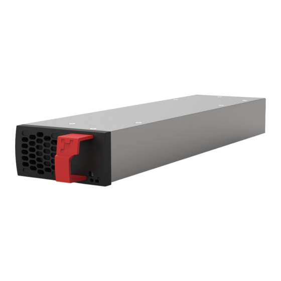
BRAVO 10 - 48/230
User Manual
BEYOND THE INVERTER
THE NEW GENERATION OF POWER CONVERTERS
•
DUAL INPUT INVERTER
Commercial Power as default source
•
AC BACKUP IN A DC ENVIRONMENT
Leverage your existing DC infrastructure
•
ONE STOP SHOP
Wide output power range
•
HARSHEST AC INPUT CONDITIONS
Without compromising the quality of the AC output
Copyright © 2024. Construction electroniques & telecommunications S.A.
All rights reserved. The contents in document are subject to change without notice.
The products presented are protected by several international patents and trademarks.
Address: CE+T S.a, Rue du Charbonnage 12, B 4020 Wandre, Belgium
www.cet-power.com - info@cet-power.com
Contact us: www.cet-power.com
|
Follow us on social media:
Version 1.5
Advertisement
Table of Contents

Subscribe to Our Youtube Channel
Related Manuals for CE+T Power BRAVO 10 48/230


Summary of Contents for CE+T Power BRAVO 10 48/230
- Page 1 BRAVO 10 - 48/230 User Manual BEYOND THE INVERTER THE NEW GENERATION OF POWER CONVERTERS • DUAL INPUT INVERTER Commercial Power as default source • AC BACKUP IN A DC ENVIRONMENT Leverage your existing DC infrastructure • ONE STOP SHOP Wide output power range •...
-
Page 2: Table Of Contents
Table of Contents 1. CE+T Power at a glance ......................... 2. Abbreviations ............................3. Warranty and Safety Conditions ......................Disclaimer ........................... Technical care ..........................Installation ..........................3.3.1 Handling ......................... 3.3.2 Surge and transients ...................... 3.3.3 Other ..........................Maintenance ..........................Replacement and Dismantling ..................... - Page 3 Controller - Inview Slot ........................ 9.2.1 Removal ......................... 9.2.2 Inserting ......................... 10. Manual By-Pass (Optional) ........................10.1 Pre-requisites ..........................10.2 MBP Auxiliary Connection ......................10.3 Manual By-Pass Operation ......................10.3.1 Normal to By-pass (Engage MBP) ................... 10.3.2 By-pass to Normal (Disengage MBP) ................11.
- Page 4 Release Note: Release date Version Modified page number Modifications (DD/MM/YYYY) 03/12/2018 First release of the manual. 19/08/2019 Added Inview S Slot information. 25/11/2019 25 to 29, 34 & 35 Updated inview S and MBP section. Updated mounting kit and fan replacement 04/06/2021 18 and 33 - 34 procedure.
-
Page 5: Ce+T Power At A Glance
1. CE+T Power at a glance CE+T Power is your trusted partner in advanced power solutions engineered to meet the demands of modern and dynamic industrial applications. With over 60 years of experience in power conversion technology, CE+T Power nurtures the industry with innovative solutions designed for critical power backup and energy management. -
Page 6: Abbreviations
Abbreviations 2. Abbreviations Alternating current Circuit Breaker Direct current DHCP Dynamic Host Configuration Protocol Digital Signal Processor Enhanced Conversion Innovation EMBS External Maintenance Bypass Switch Enhanced Power Conversion Electro Static Discharge Ethernet Ground / Grounding HTTP HyperText Transfer Protocol HTTPS Secure HyperText Transfer Protocol Local Access Network Measure Box Battery... -
Page 7: Warranty And Safety Conditions
Warranty and Safety Conditions 3. Warranty and Safety Conditions WARNING: The electronics in the power supply system are designed for an indoor, clean environment. When installed in a dusty and/or corrosive environment, indoor, it is important to: • Install an appropriate filter on the enclosure door, or on the room’s air conditioning system. •... -
Page 8: Installation
Warranty and Safety Conditions 3.3 Installation • This product is intended to be installed only in restricted access areas as defined by local regulations and in accordance with the National Electric Code, ANSI/NFPA 70, or equivalent agencies. • The Inverter System may contain output over current protection in the form of circuit breakers. In addition to these circuit breakers, the user must observe the recommended upstream and downstream circuit breaker requirements as defined in this manual. -
Page 9: Surge And Transients
Warranty and Safety Conditions 3.3.2 Surge and transients The mains (AC) supply of the modular inverter system shall be fitted with Lightning surge suppression and Transient voltage surge suppression suitable for the application at hand. Manufacturer’s recommendations of installation shall be adhered to. -
Page 10: Eci Technology
ECI Technology 4. ECI Technology A Bravo module is a triple port converter built with ECI technology. This module delivers pure sinusoidal output from AC mains or battery. The block diagram below gives an explicit description of the topology and operation. ECI technology has AC to DC, DC to AC, and DC to DC converters to provide constant and disturbance-free output power regardless of the input source. -
Page 11: On-Line Mode
ECI Technology 4.1 On-line Mode DC is the primary source of supply whilst Mains (AC) works as the secondary source. Switching time between DC input and AC input is 0 ms (source transfer). The power delivered by the DC source (usually a battery, but possibly any other type of DC generator) is converted to provide regulated and transient-free power to the load. -
Page 12: Building Blocks
Building Blocks 5. Building Blocks 5.1 Bravo 10 - 48/230 Telecom / Datacom: Input 48 Vdc 230 Vac, 50/60 Hz Output 230 Vac Power 1250 VA / 1000 W • The Bravo module is a triple port inverter. • Hot-swappable and hot-pluggable. •... - Page 13 Building Blocks DC Input Data DC voltage: Nominal / range 48 VDC / (40-60V)* Nominal current (at 48 Vdc and 1000 W output) 22.3 A Maximum input current (at 48 Vdc for 15 second) / 34 A / < 10 mV RMS voltage ripple AC Output Data Efficiency (Typical): Enhanced power conversion / on...
-
Page 14: Inverter - Led Indications
Building Blocks 5.2 Inverter - LED Indications AC OUT DC IN AC IN Output Power Status Inverter Status LED Description Remedial action No input power or forced stop Check environment Permanent green Operation Inverter OK but working conditions are Blinking green not fulfilled to operate properly Blinking green/orange alternatively Recovery mode... -
Page 15: Monitoring Device - Inview Slot, S, X And Gw
Monitoring device - Inview Slot, S, X and GW 6. Monitoring device - Inview Slot, S, X and GW Bravo 10 modules can be monitored through Inview Slot, S, X or Inview GW. For more details about these monitoring devices and the hardware connections, refer to the Inview and Inview GW user manuals. Inview Slot, S and X - https://datasheet.cet-power.com/CET - Monitoring - User Manual - Inview - EN.pdf Inview GW -... -
Page 16: A La Carte
A la Carte 7. A la Carte The A la Carte is pre-assembled and configured as a single phase or three phase system. The system comprises cabinet, inverter sub rack, Bravo 10 inverter modules and controller. Bravo 10 System with Inview S Bravo 10 System with Inview Slot Bravo 10 system featured with: •... -
Page 17: Installation Of Bravo 10 - Shelf
Installation of Bravo 10 - Shelf 8. Installation of Bravo 10 - Shelf • Read safety instructions prior starting any work. • Do NOT attempt to use lifting eyes to erect the cabinet. • System is preferable handled without modules. •... -
Page 18: Electrical Installation For Bravo 10 - Shelf
Installation of Bravo 10 - Shelf In two- and three-shelf packs, assemble the shelves separately with respective clamps, place the pack on the support, and fix it in the cabinet. Note: While assembling the pack, fix the bottom shelf first with clamps, then the middle and top shelf. •... -
Page 19: Terminations
Installation of Bravo 10 - Shelf 8.2.2 Terminations The below image is termination details of Bravo 10 - 48/230 shelf Remote ON/OFF (AC Out) (AC Out) (AC IN) (AC IN) To Inview S, X or GW (To Parallel the 8 Pin (CE+T COM port) Bravo 10 - shelves) 6 Pin... -
Page 20: Grounding
Installation of Bravo 10 - Shelf 8.2.4 Grounding “PE Chassis Ground” PE Chassis ground should be wired to MET (Main Earth Terminal) or distributed earth bar connected to MET, according to local regulations. Warning: The inverter module and shelves contain filters designed to protect against voltage surges and other disruptions. These filters have capacitors between L, N and earth (PE), which adds to the overall capacitance of the wiring system and the overall level of leakage current. -
Page 21: Ac Output Connection
Installation of Bravo 10 - Shelf Model MCB per Shelf Cable, min Connector Torque Insulated Ring Bravo 10 - 48/230 40 A 6 mm 5 Nm type Note: Icc value measured as 50 A per shelf with five modules. 8.2.7 AC Output Connection Model MCB per Shelf Cable, min... - Page 22 Installation of Bravo 10 - Shelf • The remote ON/OFF can be connected to any shelf. • The remote ON/OFF requires changeover contacts, one input opens as the other close. If both transitions are not picked up the status is not changed. Relay characteristics (Remote ON/OFF) •...
-
Page 23: Replacement Procedures
Replacement procedures 9. Replacement procedures 9.1 Module - Bravo 10 • The Bravo inverter is hot swappable. • When a new module is inserted in a live system it automatically adapts to a working set of parameters. • When a new module is inserted in a live system it automatically assigns the next available address. Caution: After removing a module from a slot in a live system, wait at least 60 seconds before inserting it into another slot;... -
Page 24: Controller - Inview Slot
Replacement procedures 9.2 Controller - Inview Slot 9.2.1 Removal 1. Insert a soft edged pin into the hole to unlock the latch. (Hole diameter is 3 mm) 2. Gently push and press down the pin to unlock the latch and then remove the controller. Warning: While removing the controller from the shelf, hold the top and bottom part of front plastic. -
Page 25: Manual By-Pass (Optional)
Manual By-Pass (Optional) 10. Manual By-Pass (Optional) Manual By-Pass has to be operated by trained people only. When system is in manual by-pass the load is subjected to mains voltage without active filtering. Output alarm is activated when system is in manual by-pass. The Manual By-Pass cannot be operated remotely. -
Page 26: Manual By-Pass Operation
Manual By-Pass (Optional) INVIEW SLOT X5/2 DIG IN AUX1 RJ485 X5/3 From REMOTE ON/OFF MBP AUX CONTACT X5/1 AUX3 Module shelf rear MBP auxiliary connection in Inview Slot The Digital Input Mode must configure as below through Inview web Interface: •... -
Page 27: Finishing
Finishing 11. Finishing • Make sure that the sub-rack/cabinet is properly fixed to the cabinet/floor • Make sure that the sub-rack/cabinet is connected to Ground. • Make sure that all DC and AC input breakers are switched OFF. • Make sure that all cables are according to recommendations and local regulations. •... -
Page 28: Commissioning
Commissioning 12. Commissioning The DC breaker is a protection device. Modules are plugged in a system and DC breaker is then engaged. Please make sure the corresponding DC breaker is engaged in the ON position. Failure to observe this rules will result not to have all module operating when running on DC and have module failure when AC input recover from fault condition. -
Page 29: Check List
Commissioning 12.1 Check list DATA Date Performed by Site System serial number Module serial numbers Inview GW/S/X Serial number ACTION OK/ N.OK Unplug all inverters except one inverter per phase (Just pull off the inverter from the shelf, to interrupt electrical contacts) Check the commercial AC before closing the AC input breaker. -
Page 30: Trouble Shooting And Defective Situations Fixing
Trouble Shooting and Defective Situations Fixing 13. Trouble Shooting and Defective Situations Fixing 13.1 Trouble Shooting Inverter module does not power up: Check AC input present and in range (AC breakers) Check DC input present and in range (DC breakers) Check that the inverter is properly inserted Remove inverter to verify that slot is not damaged, check connectors Check that module(s) is (are) in OFF state... -
Page 31: Defective Modules
• The RMA number should be mentioned on all shipping documents related to the repair. • Be aware that products shipped back to CE+T Power without being registered first will not be treated with high priority. - Bravo 10 - 48/230 - User manual - v1.5... -
Page 32: Maintenance
Maintenance 14. Maintenance Maintenance shall only be performed by properly trained people. 14.1 Access Inview with Laptop • Download system LOG FILE and save. - Analyze log file and correct errors. • Download system CONFIGURATION FILE and save. - Check/correct configuration file according to operation conditions. - Check/correct alarm configuration. -
Page 33: Service
Service 15. Service For Service • Check Service Level Agreement (SLA) of your vendor. Most of the time they provide assistance on call with integrated service. If such SLA is in place, you must call their assistance first. • If your vendor doesn’t provide such assistance (*) you may contact CE+T through email: ƒ... -
Page 34: Appendix
Appendix 16. Appendix 16.1 Mains connection - Single phase TN - S (400/230VAC) TN - C - S (400/230VAC) TN - C (400/230VAC) TT (400/230VAC) - Bravo 10 - 48/230 - User manual - v1.5... -
Page 35: Mains Connection - Three Phases
Appendix 16.2 Mains connection - Three phases TN - S (400/230VAC) TN - C - S (400/230VAC) TN - C (400/230VAC) TT (400/230VAC) - Bravo 10 - 48/230 - User manual - v1.5... -
Page 36: Bravo 10 - 48/230 - Dimensions
Appendix 16.3 Bravo 10 - 48/230 - Dimensions 16.3.1 Module 86.50 Front View 314.30 324.50 345.73 Le Side View 16.3.2 Shelf Le View Front View 34.50 446.60 TYP. TYP. Detail A Detail B Scale 1 : 2 Scale 1 : 2 Right View All dimensions are in mm Top View... -
Page 37: Bravo 10 - Parallel Kit 2/3 Shelves
Appendix 16.4 Bravo 10 - Parallel Kit 2/3 shelves The purpose of the kit is to parallelize the Sierra/Bravo 10 shelves (2 or 3 shelves only) in a 1-Phase configuration or 3-Phase configuration (3-PH configuration is only available with 3 shelves). •... -
Page 38: Copper Bar Placement, Cables Connection And Screws Adaptation
Appendix 16.4.3 Copper bar placement, Cables connection and Screws adaptation It is important to respect screws and cable lug position as defined below. Screws size have been adapted taking into account copper bar and lugs in order to ensure connections and respect dielectric distances. 16.4.3.1 3 Shelves Configuration - 3 Phase - Bravo 10 - 48/230 - User manual - v1.5... - Page 39 Appendix 16.4.3.2 3 Shelves Configuration - 1 Phase - Bravo 10 - 48/230 - User manual - v1.5...
- Page 40 Appendix 16.4.3.3 2 Shelves Configuration – 1 Phase Note: AC & DC cable connection from customer side to the system shall be with proper cable & lug based on the power rating. The Lug size must be M6. Once the above assembly procedures are completed, Sierra/Bravo 10 modules can be plugged into the shelf. - Bravo 10 - 48/230 - User manual - v1.5...
-
Page 41: Modules - Parameter List
Appendix 16.5 Modules - Parameter List With Inview, you can access the modules’ parameter list and descriptions. Refer to the Inview and Inview GW user manuals to access the Inview web interface. Inview Slot, S and X - https://datasheet.cet-power.com/CET - Monitoring - User Manual - Inview - EN.pdf Inview GW - https://datasheet.cet-power.com/CET - Monitoring - User Manual - Inview GW - EN.pdf If you want to have an overview of standard systems’...
Need help?
Do you have a question about the BRAVO 10 48/230 and is the answer not in the manual?
Questions and answers