Table of Contents
Advertisement
Quick Links
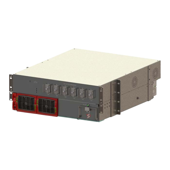
BRAVO ST - 120 VAC - UL
User Manual V7.2
BEYOND THE INVERTER
THE NEW GENERATION OF POWER CONVERTERS
•
DUAL INPUT INVERTER
Commercial Power as default source
•
AC BACKUP IN A DC ENVIRONMENT
Leverage your existing DC infrastructure
•
ONE STOP SHOP
Wide output power range
•
HARSHEST AC INPUT CONDITIONS
Without compromising the quality of the AC output
Copyright © 2013. Construction electroniques & telecommunications S.A.
All rights reserved. The contents in document are subject to change without notice.
The products presented are protected by several international patents and trademarks.
Address: CE+T S.a, Rue du Charbonnage 12, B 4020 Wandre, Belgium
www.cet-power.com - info@cet-power.com
Belgium, China, India, Luxembourg, Malaysia, Russia, United Kingdom, United States, Australia & Germany
www.cet-power.com
Advertisement
Table of Contents
Troubleshooting

Subscribe to Our Youtube Channel
Related Manuals for CE+T Power BRAVO ST-120 VAC-UL


Summary of Contents for CE+T Power BRAVO ST-120 VAC-UL
- Page 1 BRAVO ST - 120 VAC - UL User Manual V7.2 BEYOND THE INVERTER THE NEW GENERATION OF POWER CONVERTERS • DUAL INPUT INVERTER Commercial Power as default source • AC BACKUP IN A DC ENVIRONMENT Leverage your existing DC infrastructure •...
-
Page 2: Table Of Contents
Table of content 1. CE+T at a glance ........................... 2. Abbreviations ............................3. Warranty and Safety Conditions ......................Disclaimer ........................... Technical care ..........................Installation ..........................3.3.1 Handling ......................... 3.3.2 Surge and transients ...................... 3.3.3 Other ..........................Maintenance ..........................Replacement and Dismantling ..................... 4. - Page 3 8.3.6 DC Input ......................... 8.3.7 AC Input (AC Input protection mandatory) ............... 8.3.8 AC Output ........................8.3.9 Signalling ........................Wiring - Receptacle ........................8.4.1 6 X (2 x NEMA 15R Receptacles) ..................8.4.2 2 X (2 X NEMA 15R Receptacles), 4 X (1 X NEMA 20R Receptacles) ........ 8.4.3 6 X (1 x NEMA 20R Receptacles) ..................
- Page 4 Release Note: Release date Modified page Version Modifications (DD/MM/YYYY) number 16/12/2015 First release of the Manual. 11/11/2016 Amendment and correction. 05/06/2020 New layout – Bravo ST 120 VAC– User Manual – v7.2...
-
Page 5: Ce+T At A Glance
CE+T at a glance 1. CE+T at a glance CE+T Power designs, manufactures and markets a range of products for industrial operators with mission critical applications, who are not satisfied with existing AC backup systems performances, and related maintenance costs. -
Page 6: Abbreviations
Abbreviations 2. Abbreviations Twin Sine Innovation Enhanced Power Conversion Regular Digital Signal Processor Alternating current Direct current Electro Static Discharge Main Earth Terminal Manual By-pass TCP/IP Transmission Control Protocol/Internet Protocol Universal Serial Bus Protective Earth (also called Main Protective Conductor) Neutral Printed Circuit Board True Redundant Structure... -
Page 7: Warranty And Safety Conditions
Warranty and Safety Conditions 3. Warranty and Safety Conditions WARNING: The electronics in the power supply system are designed for an indoor, clean environment. When installed in a dusty and/or corrosive environment, outdoor or indoor, it is important to: • Install an appropriate filter on the enclosure door, or on the room’s air conditioning system. •... -
Page 8: Installation
Warranty and Safety Conditions • CAUTION – Risk of electric shock. This Inverter / UPS receives power from more than one source. Disconnection of the AC source and DC source is required to de-energize this unit before servicing. • CAUTION - For continued protection against risk of fire, replace only with same type and rating of fuse. -
Page 9: Surge And Transients
Warranty and Safety Conditions 3.3.2 Surge and transients The mains (AC) supply of the modular inverter system shall be fitted with Lightning surge suppression and Transient voltage surge suppression suitable for the application at hand. Manufacturer’s recommendations of installation shall be adhered to. -
Page 10: Tsi Technology
TSI TECHNOLOGY 4. TSI TECHNOLOGY Inverter modules carrying the TSI logo and the EPC mark are triple port converters (AC in, DC in, AC out). Sinusoidal output is converted from Mains or/and DC. The following block diagram gives an explicit description of the topology and operation. BOOST L’... -
Page 11: Epc Mode
TSI TECHNOLOGY 4.1 EPC Mode • Mains input (AC) is the primary source whilst DC works as backup. • The TSI is designed to operate on Mains on a permanent basis and to deliver output voltage conditioned with low THD. •... -
Page 12: Description
Description 5. Description Bravo ST has been designed to give quality power, ease of use, and reliability. It provides up to 4000 watts (Bravo ST 5 KVA) or up to 2000 watts (Bravo ST 2.5 KVA). In normal operation: • AC input present the TSI module will operate in EPC mode. •... -
Page 13: Typical Load
Description Bravo ST 120 VAC is a standalone Inverter with following capacities. • Standalone model 5000 VA. • Standalone model 2500 VA, with Redundancy. • Standalone model 2500 VA, without Redundancy. 120 Vac and 48/110 Vdc as Input and 120 Vac as Output fitted with Enhanced Power Conversion (EPC) mode. Front View Rear View 5.1 Typical load... -
Page 14: Bravo St Components
Bravo ST Components 6. Bravo ST Components 6.1 Inverter Module Bravo: 48 VDC 2500 VA -120 VAC. 110 VDC 2500 VA -120 VAC. • The BRAVO module shall have software version V203 or higher to operate with BRAVO ST. • The TSI Bravo is a 2500 VA / 2000 W converter based on the TSI technology (see section 4, page 10). •... -
Page 15: Sub-Rack
Bravo ST Components 6.3 Sub-rack • The BRAVO ST 120 VAC shelf shall be integrated in min 600 mm deep cabinets, 19 inch / ETSI mounting. • The BRAVO ST 120 VAC shelf houses maximum two (2) inverter modules and one (1) T2S interface. Maximum 5 KVA per shelf. -
Page 16: Accessories
Accessories 7. Accessories 7.1 T2S Interface The T2S is an interface giving access to the TSI modules that are connected together in any TSI systems. The T2S doesn’t perform any control or management of the TSI system. It can be removed, replaced or moved to another live system without affecting neither the original TSI system operation nor the target system. -
Page 17: Bravo St System Installation
Bravo ST System Installation 8. Bravo ST System Installation 8.1 Unpacking the system BRAVO ST is packed in a wooden box. Modules are packed separately. They are normally marked to be replaced in the right slot. Module packing material shall be taken apart and stored in case of return under warranty. Unproper packing may void the warranty. -
Page 18: Fixing The System To Cabinet
Bravo ST System Installation 8.2.2 Fixing the System to Cabinet CE+T offers adapter plates to mount the Bravo ST System into the 23-inch open relay racks. These can be ordered by contacting CE+T. All Bravo ST Systems are designed for 19-inch mounting applications, but it can be mounted in 23-inch, two post, open relay rack/ network frame assemblies if required in application. - Page 19 Bravo ST System Installation 8.2.2.2 Fixing the System into 23 inch Cabinet Place the bracket in the cabinet. Fix the bracket with supplied mounting screws. Fix the System with supplied mounting screws. – Bravo ST 120 VAC– User Manual – v7.2...
-
Page 20: Electrical Installation
Bravo ST System Installation 8.3 Electrical Installation 8.3.1 Pre-requisites • The system have markings for all terminations. • All cables shall be rated at min 90° C. • Electrical terminations shall be tightened with 5 Nm. • DC connection screws are M6 x 12 mm and AC connection with terminal block. •... -
Page 21: Terminations
Bravo ST System Installation 8.3.3 Terminations Rear Side of Bravo ST 120 VAC terminations are clearly marked in the following figure. 8.3.4 Grounding “PE CHASSIS GROUND” PE Chassis ground shall be wired to MET or distributed earth bar connected to MET, according to local regulations. Main protective conductor (PE) connection is made to the X2 (AC IN) terminal block marked with symbol for identification. -
Page 22: Ac Input And Output
Bravo ST System Installation 8.3.5 AC Input and Output The pictorial representation of terminal blocks arrangement is as follows. If AC IN is connected, remove the bonding neutral jumper cable between AC IN Neutral and PE terminal. 8.3.6 DC Input Individual Feed Common Feed Torque... -
Page 23: Ac Input (Ac Input Protection Mandatory)
Bravo ST System Installation 8.3.7 AC Input (AC Input protection mandatory) Torque Model Breaker Cable Min Cable Max lb.in 48 VDC 60 A / 1P 1 X 4 AWG 1 X 2 AWG 24.9 - 26.7 110 VDC 8.3.8 AC Output Torque Model Cable Min... -
Page 24: Wiring - Receptacle
Bravo ST System Installation 8.4 Wiring - Receptacle TSI Bravo ST 120 VAC can be configured with NEMA or with hardwired AC Output connection. 8.4.1 6 X (2 x NEMA 15R Receptacles) 8.4.2 2 X (2 X NEMA 15R Receptacles), 4 X (1 X NEMA 20R Receptacles) –... -
Page 25: Nema 20R Receptacles)
Bravo ST System Installation 8.4.3 6 X (1 x NEMA 20R Receptacles) 8.4.4 Bulk Output – Bravo ST 120 VAC– User Manual – v7.2... -
Page 26: Human-Machine Interface
Human-Machine Interface 9. Human-Machine Interface 9.1 Inverter module (Requires firmware V203 or higher) AC OUT DC IN AC IN Inverter Status Output Power Status Inverter Status LED Description Remedial action No input power or forced stop Check environment Permanent green Operation Converter OK but working conditions Blinking green... -
Page 27: T2S
Human-Machine Interface 9.2 T2S • T2S has two new parameters. ƒ 420 ST module number 0,1,2 define the number of BRAVO in the configuration. ƒ 421 ST module redundancy 0 or 1. Note: The BRAVO module V203 or higher those parameters appear automatically and T2S is pre configured in factory. •... -
Page 28: System Set Up
System set up 10. System set up Bravo ST 120 VAC System is delivered with default set of parameters referred as factory settings. Upon various site operating conditions or Site Manager requirements some parameters might have to be adjusted. Refer to “TSI T2S 120VAC User Manual Vx_x” for detailed description of system status reading and changing as well as parameter adjustment. -
Page 29: Menu Access
System set up 10.2 Menu access Root Menu 1 > System configuration 0 > Return to previous menu 1 > Send config file to T2S 2 > Read config file from T2S 3 > Restore default settings (not available since version 2.5) 4 >... -
Page 30: Inserting/Removing/Replacing Modules
Inserting/removing/replacing modules 11. Inserting/removing/replacing modules 11.1 TSI Inverter • The TSI inverter module is hot swappable. BRAVO ST operate with module having firmware V203 or higher. • When a new module is inserted in a live system it automatically takes the working set of parameters. •... -
Page 31: Module Removal
Inserting/removing/replacing modules 11.1.1 Module Removal Notice: When one or several inverter modules is/are removed, live parts become accessible. Replace module(s) with dummy cover without delay. 1. The inverter module is not switched off when opening the handle. The handle only hooks the module to the shelf. 2. -
Page 32: Tsi By-Pass Module Replacement
Inserting/removing/replacing modules 11.2 TSI By-Pass Module Replacement 11.2.1 Removal Note : Before replacing the By-Pass Module please make sure the inverter module are in operation and both AC input and DC input source are available. Step 1: Unscrew the screw in anti clockwise direction. Step 2: Remove the front clamp. -
Page 33: Inserting
Inserting/removing/replacing modules 11.2.2 Inserting Step 1: Take a new By-Pass Module. Step 2: Using the handle, gently push the By-Pass Module into the shelf and close the handle in vertical position. Step 3: Place the front clamp. Step 4: Tight the screw in clockwise direction. –... -
Page 34: T2S
Inserting/removing/replacing modules 11.3 T2S 11.3.1 Removal • Use a small screw driver to release the latch keeping the T2S in position. • Pull the T2S out. 11.3.2 Inserting • Push the T2S firmly in place until the latch snaps into position. 11.4 Fan replacement The FAN life is approximately 60,000 (Sixty Thousand) hours. -
Page 35: Final Check
Final check 12. Final check • Make sure that the system is properly mounted in the cabinet/floor. • Make sure that the system is connected to Ground. • Make sure that all DC and AC input breakers are switched OFF. •... -
Page 36: Commissioning
Commissioning 13. Commissioning The DC breaker is a protection device. Modules are plugged into a system and the DC breaker is then engaged. Please make sure that the corresponding DC breaker is engaged in the ON position. Failure to observe this rule will result in not all modules operating when running on DC, and module failure when the AC input recovers from the fault condition. -
Page 37: Check List
Commissioning 13.1 Check list DATA Date Performed by Site System serial number Module serial numbers T1S/T2S serial number-Specify T1S/T2S ACTION OK/ N.OK Unplug all inverters except one inverter per phase (Just pull the inverter out from the shelf, to break electrical contact Check the commercial AC power before closing the AC input breaker. -
Page 38: Trouble Shooting And Defective Situations Resolution
Trouble Shooting and Defective Situations Resolution 14. Trouble Shooting and Defective Situations Resolution 14.1 Trouble Shooting Inverter module does not power up: Check AC input present and in range (AC breakers) Check DC input present and in range (DC breakers) Check that the inverter is properly inserted Remove inverter to verify that slot is not damaged, check connectors Check that module(s) is (are) in OFF state... -
Page 39: Defective Modules
• Before returning a defective product, a RMA number must be requested by email at tech.support@cetamerica.com. • The RMA number should be mentioned on all shipping documents related to the repair. • Be aware that products shipped back to CE+T Power without being registered first will not be treated with high priority! •... -
Page 40: Service
Service 15. Service For Service • Check Service Level Agreement (SLA) of your vendor. Most of the time they provide assistance on call with integrated service. If such SLA is in place, you must call their assistance first. • If your vendor doesn’t provide such assistance (*) you may call CE+T directly. Toll free Number 1(855) 669 - 4627(**) Service is available from 8:00 A.M. -
Page 41: Maintenance Task
Maintenance Task 16. Maintenance Task As maintenance will be performed on live system, all task should be performed only by trained personnel with sufficient knowledge on TSI product. Tasks: • Identify the site, customer, rack number, product type. • Download and save configuration file for back up. •...
Need help?
Do you have a question about the BRAVO ST-120 VAC-UL and is the answer not in the manual?
Questions and answers