Table of Contents
Advertisement
Quick Links
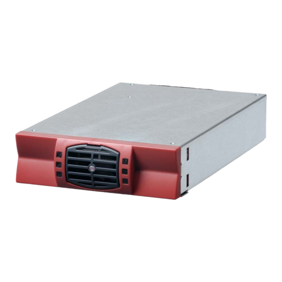
TSI VEDA - 230VAC
User Manual V7.1
BEYOND THE INVERTER
THE NEW GENERATION OF POWER CONVERTERS
SINGLE INPUT INVERTER
The DC Power as default source
AC BACKUP IN A DC ENVIRONMENT
Leverage your existing DC infrastructure
ONE STOP SHOP
wide output power range
Copyright © 2013. Construction electroniques & telecommunications S.A.
All rights reserved. The contents in document are subject to change without notice.
The products presented are protected by several international patents and trademarks.
Address: CE+T S.a, Rue du Charbonnage 12, B 4020 Wandre, Belgium
www.cet-power.com - info@cet-power.com
www.cet-power.com
Advertisement
Table of Contents

Subscribe to Our Youtube Channel
Related Manuals for CE+T Power TSI VEDA


Summary of Contents for CE+T Power TSI VEDA
- Page 1 TSI VEDA - 230VAC User Manual V7.1 BEYOND THE INVERTER THE NEW GENERATION OF POWER CONVERTERS SINGLE INPUT INVERTER The DC Power as default source AC BACKUP IN A DC ENVIRONMENT Leverage your existing DC infrastructure ONE STOP SHOP wide output power range Copyright ©...
-
Page 2: Table Of Contents
9.1 Unpacking the system ............................9.2 Raising the cabinet ............................9.3 Fixing the cabinet to the floor ..........................9.4 Electrical installation ............................9.4.1 Positioning ............................9.4.2 Cabling ..............................9.4.3 Grounding ............................. 9.4.4 DC input (X1) ............................– TSI VEDA – User manual – v7.1... - Page 3 17.1 Access T2S with lap top ............................ 17.2 Manual check ..............................17.3 Optional ................................18. Defective modules ..............................19. Appendix .................................. 19.1 Cabinet foot print, layout ........................... 19.2 Single phase circuit diagram ..........................– TSI VEDA – User manual – v7.1...
-
Page 4: Abbreviations
1. Abbreviations Twin Sine Innovation Enhanced Power Conversion Regular Digital Signal Processor Alternating current Direct current Electro Static Discharge Main Earth Terminal Manual By-pass TCP/IP Transmission Control Protocol/Internet Protocol Universal Serial Bus – TSI VEDA – User manual – v7.1... -
Page 5: Safety Instructions
If the equipment is dismantled, to dispose of the products it consists of, you must stick to the local regulations in force in the country of destination and in any case avoid causing any kind of pollution. – TSI VEDA – User manual – v7.1... -
Page 6: Handling
„ „ Empty inverter positions must not be left open. Replace with module or cover. „ „ 2.2 Other „ „ Isolation test must not be performed without instructions from the manufacturer. – TSI VEDA – User manual – v7.1... -
Page 7: Tsi Technology
The TSI works according to True Redundant Structure (TRS) that features decentralized logic, redundant communication bus and three levels of, individually independent, disconnection. Isolation test must not be performed without instructions from the manufacturer. L’ FILTER FILTER N’ User Interface Redundant Local Signaling Commuication – TSI VEDA – User manual – v7.1... -
Page 8: Building Blocks
Telecom / Datacom: -48VDC / 230VAC, 50/60Hz „ „ The TSI Veda is a 600VA/480W (-25 upto +50 deg C), above +50 degree C ,power derated to 500VA/400W(upto +65 deg C) dual port inverter. All versions available in REG. „... -
Page 9: Monitor Unit T1S/T2S
Record the latest 200 events. Fi-Fo „ „ 3 outgoing alarms 2 digital input „ „ MOD bus (Default) „ „ „ „ CAN bus (Optional) „ „ USB front connector for local setting – TSI VEDA – User manual – v7.1... -
Page 10: Accessories
Max current per AC DU is 20A, max current per output connector is 6A ,applicable only upto 4.5KVA A la Carte system/pack. Alarm for AC output breakers is present (OF or SD). The alarm function is common and use one of the digital input on the control unit. – TSI VEDA – User manual – v7.1... -
Page 11: Monitoring Accessories
6.1.1 Display Backlit 2 line dot matrix The display show two values simultaneous 6.1.2 TCP/IP Agent The TCP/IP interface board is mounted on the CanDis shelf and is powered within the system. – TSI VEDA – User manual – v7.1... -
Page 12: System Design
Always conditioned and filtered output voltage „ „ No single point of failure Flexible AC output distribution „ „ T2S MOD bus default, T2S CAN bus optional „ „ Full modularity „ „ „ „ Full redundancy – TSI VEDA – User manual – v7.1... -
Page 13: Installation Of Veda Pack Or Single Shelf/Shelves
Fix cage nuts (5) in the cabinet front and rear frame of the left and the right side Fix the left and right slider of the cabinet with the supplied screws (4) – TSI VEDA – User manual – v7.1... -
Page 14: Pre Requisites
Wire all positions in the sub-rack for future expansion Output AC / Input DC / Signal cables shall be separated „ „ Cable crossings shall be done in 90 deg angles „ „ – TSI VEDA – User manual – v7.1... -
Page 15: Terminations
( - ) terminal and the first ( + ) terminal correspond to the left inverter on the front. Same thing for center ( - ) terminal and the center ( + ) terminal correspond to the center inverter on the front, etc. – TSI VEDA – User manual – v7.1... -
Page 16: Ac Output
2A at 30VDC / 1A at 60VDC „ „ Max wire size Digital input characteristics (Digital In 1 / 2) Signal voltage +5VDC (galvanic insulated) „ „ Max wire size „ „ – TSI VEDA – User manual – v7.1... -
Page 17: Remote On/Off
Pin 1-3 Pin 2-3 Status Indication Open Open Normal operation All (Green) Closed Open AC output (OFF) DC Input (Green) Open Closed Normal operation All (Green) Closed Closed Normal operation All (Green) – TSI VEDA – User manual – v7.1... -
Page 18: Internal Bus (Tsi Bus 6 Pin / Tsi Bus 8 Pin)
The internal bus connectors are sensitive and special caution should be taken during installation to keep them out of harms way The internal bus is connected from the first shelf to the last shelf. „ „ – TSI VEDA – User manual – v7.1... -
Page 19: Installation Of Cabinet (A La Carte)
Output AC / Input DC / Signal cables shall be separated „ „ Cable crossings shall be done in 90 deg angles Empty inverter positions shall be covered with blanks „ „ – TSI VEDA – User manual – v7.1... -
Page 20: Positioning
The top cover is possible to split in three parts to facilitate cabling. The top cover has support to strap the cables with nylon tie straps. Ground DC Input (X1) Alarm (X3, X5, X6) AC Output (X4) – TSI VEDA – User manual – v7.1... -
Page 21: Grounding
Note: Screws and nuts are not included in the delivery. M12 holes „ „ Internal DC distribution with circuit breakers (Q01-Q24) per inverter module. „ „ „ „ Max 1x240mm per pole – TSI VEDA – User manual – v7.1... - Page 22 (Two terminal for one shelf) + - + - + - + - + - + - + - + - + - + - + - + - – TSI VEDA – User manual – v7.1...
-
Page 23: Connection Table Dc Input -48Vdc (X1)
Cable lug Screw terminal/cable lug Fuse/CB Min. Cable mm Fuse/CB Min Cable mm 100A 160A Live: Screw terminal 180A 1.5mm 250A Common: Ferrule. 10.8 300A 1.5 mm -1,5Nm torque 12.6 315A 14.4 400A – TSI VEDA – User manual – v7.1... -
Page 24: Signalling
9.4.6 Signalling All relays are in non energized position – TSI VEDA – User manual – v7.1... - Page 25 Initial start of system must be performed with operational T2S. Should the T2S be missing at start-up the modules will fail to start. The following sequence of the Remote ON/OFF will force system to start without the T2S #3 ==> #2 ==> #3 will force modules to start. – TSI VEDA – User manual – v7.1...
-
Page 26: Interface
40 to 80 to 100% = <5% 100% Output Power (redundancy not counted) overload × × × × × Status output power LED × Behavior (B = blinking – P permanent ) – TSI VEDA – User manual – v7.1... -
Page 27: T1S
User selectable Alarm - Non urgent 30 second delay „ „ Parameter setting via Laptop or Copy/Paste. USB port „ „ Factory default according to list of set values, see Table of set values – TSI VEDA – User manual – v7.1... -
Page 28: System Set Up
Read T2S manual for detailed setup 11.1 Communication setting Bits per second 115200 „ „ „ „ Data bits „ „ Parity None Stop bits „ „ Flow control None „ „ – TSI VEDA – User manual – v7.1... -
Page 29: Menu Access
0 > Return to index 1 > Force refresh of configuration textes and constants 2 > Force refresh of events description texts 4 > Security Access 0 > Return to index 1 > Enable Password protection – TSI VEDA – User manual – v7.1... -
Page 30: Inserting/Removing/Replacing Modules
„ „ A) Slide the module in B) Push firmly till the connection is C) Close the cover and latch the module properly engaged in place if too hard redo step B – TSI VEDA – User manual – v7.1... -
Page 31: T1S/T2S
Replace front, make sure that the front latch properly. „ „ Plug in Check fan for operation „ „ Access T2S and reset the fan run time alarm from within the action menu „ „ – TSI VEDA – User manual – v7.1... -
Page 32: Ac Output Distribution
Insert Insulated screw driver in the terminal to load the spring Insert connection cable and remove screw driver Connect load cable to breaker, Neutral and Ground Switch breaker ON Remove breaker in reverse order – TSI VEDA – User manual – v7.1... -
Page 33: Finishing
Cover empty inverter positions with blanks. „ „ „ „ Make sure that the Remote ON/OFF is appropriately wired according to local regulations. „ „ Make sure that the point of AC supply meets local regulations. – TSI VEDA – User manual – v7.1... -
Page 34: Commissioning
Installation and commissioning must be done and conducted by trained people fully authorized to act on installation. It is prohibited to perform any isolation test without instruction from manufacturer. Equipments are not cover by warranty if procedures are not respected. – TSI VEDA – User manual – v7.1... -
Page 35: Check List
Switch OFF AC input (commercial power failure) and check the alarm according to the configuration (Not applicable for REG Module) Switch OFF DC input (DC power failure) and check that the alarm according to the configuration Check the different digital input according to the configuration (when used) – TSI VEDA – User manual – v7.1... -
Page 36: Trouble Shooting
Check that the RJ45 cable is connected between T2S shelf and CanDis shelf No value on TCP/IP: Check that the RJ45 cable is connected between T2S shelf and CanDis shelf Wait approx 2 minutes to allow the system to collect serial data. – TSI VEDA – User manual – v7.1... -
Page 37: Maintenance
Validate input voltage (DC input, AC output) with multi-meter Replace dust filter „ „ Take a snap shot of the cabinet „ „ 17.3 Optional „ „ With an infrared camera check termination hot spots - Tighten terminations – TSI VEDA – User manual – v7.1... -
Page 38: Defective Modules
The RMA number should be mentioned on all shipping documents related to the repair. „ „ Be aware that products shipped back to CE+T Power without being registered first will not be treated with high priority! – TSI VEDA – User manual – v7.1... -
Page 39: Appendix
19. Appendix 19.1 Cabinet foot print, layout – TSI VEDA – User manual – v7.1... -
Page 40: Single Phase Circuit Diagram
19.2 Single phase circuit diagram – TSI VEDA – User manual – v7.1...
Need help?
Do you have a question about the TSI VEDA and is the answer not in the manual?
Questions and answers