Table of Contents
Advertisement
Quick Links
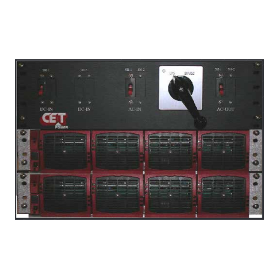
RmS SySTEm- 120vAC
user manual v7.1
BEyonD ThE InvERTER
ThE nEW gEnERATIon of poWER ConvERTERS
DuAl InpuT InvERTER
The Commercial power as default source
AC BACkup In A DC EnvIRonmEnT
leverage your existing DC infrastructure
onE STop Shop
wide output power range
hARShEST AC InpuT ConDITIonS
Without compromising the quality of the AC output
Copyright © 2013. Construction electroniques & telecommunications S.A.
All rights reserved. The contents in document are subject to change without notice.
The products presented are protected by several international patents and trademarks.
Address: CE+T S.a, Rue du Charbonnage 12, B 4020 Wandre, Belgium
www.cet-power.com - info@cet-power.com
www.cet-power.com
Advertisement
Table of Contents

Subscribe to Our Youtube Channel
Related Manuals for CE+T Power RMS SYSTEM 120Vac


Summary of Contents for CE+T Power RMS SYSTEM 120Vac
- Page 1 RmS SySTEm- 120vAC user manual v7.1 BEyonD ThE InvERTER ThE nEW gEnERATIon of poWER ConvERTERS DuAl InpuT InvERTER The Commercial power as default source AC BACkup In A DC EnvIRonmEnT leverage your existing DC infrastructure onE STop Shop wide output power range hARShEST AC InpuT ConDITIonS Without compromising the quality of the AC output Copyright ©...
-
Page 2: Table Of Contents
Table of content 1. Abbreviations ................................2. Safety instructions ..............................2.1 handling ................................2.2 Surge and transients ............................2.3 other ................................3. TSI TEChnology ..............................3.1 EpC-mode ................................ 3.2 on-line EpC ..............................3.3 Safe mode ................................ 3.4 REg-mode ................................ 4. Building blocks ................................. 4.1 Inverter ................................ - Page 3 8.3.12 Connection Table – DC Input ........................ 8.3.13 Connection Table AC output ........................9. Interface ................................... 9.1 Inverter module ..............................9.2 T2S .................................. 10. System set up ................................10.1 Communication setting ............................. 10.2 menu access ..............................11. Inserting/removing/replacing modules ........................11.1 TSI Inverter ...............................
-
Page 4: Abbreviations
1. Abbreviations Twin Sine Innovation Enhanced power Conversion Regular Digital Signal processor Alternating current Direct current Electro Static Discharge main Earth Terminal manual By-pass TCp/Ip Transmission Control protocol/Internet protocol universal Serial Bus – RmS SySTEm – user manual –v7.1... -
Page 5: Safety Instructions
2. Safety instructions „ „ The modular inverter system/rack can reach hazardous leakage currents. Earthing must be carried out prior energizing the system. Earthing shall be made according to local regulations. prior any work conducted to a system/unit make sure that AC input voltage and DC input voltage is disconnected. „... -
Page 6: Handling
„ „ for technical support for any CE+T products, or product training, please call your local CE+T America representative or CE+T America directly at 678-405-4636 To download the latest documentation and software, please visit our website at www.cet-power.com. „ „ 2.1 handling „... -
Page 7: Tsi Technology
3. TSI TEChnology Inverter modules carrying the TSI logo and the EpC mark is a triple port converter (AC in, DC in, AC out). Sinusoidal output converted from mains or/and DC. Typical loads „ „ Resistive load Inductive and resistive „... -
Page 8: On-Line Epc
3.2 on-line EpC DC is the priority source of supply whilst mains (AC) work as the secondary source of supply. Switching time between DC input and AC input is 0ms (source transfer). Regardless of supply source the output voltage is always conditioned, low ThD (sinusoidal output) Boost function is enabled without delay 3.3 Safe mode Safe mode use DC as primary source of supply while mains (AC) is standby. -
Page 9: Building Blocks
4. Building blocks 4.1 Inverter Telecom / Datacom: -48vDC / 120vAC/240vAC, 60hz „ „ The TSI media is a 1500vA/1200W triple port inverter. All versions available in EpC or REg. „ „ The TSI inverter modules are hot swappable and hot pluggable. „... -
Page 10: Monitor Unit T2S
4.3 monitor unit T2S The T2S monitors max 32 inverters in one bus The T2S provides „ „ Alarm monitoring Record the latest 200 events. fi-fo „ „ 3 outgoing alarms „ „ 2 digital input „ „ „ „ moD bus „... -
Page 11: Accessories
5. Accessories 5.1 manual by-pass The mBp is a manually activated switch that permits the user to transition the load to the AC mains temporarily so the Inverter System may be serviced safely. During standard operation, the mBp switch is placed in the upS position, allowing the system inverters to operate from incoming AC or DC sources. -
Page 12: Rms T Box Unit
5.2 RmS T BoX unit 5.2.1 T BoX BREAkERS All RmS Inverter Systems includes ul recognized circuit breakers for AC and DC input as well as AC output circuits. These circuit breakers are not in lieu of ul listed ,upstream and downstream circuit breakers to be selected in accordance with recommendation and installed by the user. -
Page 13: Monitoring Accessories
6. monitoring accessories 6.1 Can Dis shelf The CanDis shelf has room for 1-3 display units and 1 TCp/Ip agent. 6.1.1 Display Backlit 2 line dot matrix The display show two values simultaneous 6.1.2 TCp/Ip Agent The TCp/Ip interface board is mounted on the CanDis shelf and is powered within the system. –... -
Page 14: System Design
7. System Design 7.1 Single/Dual phase The systems designed are divided in single or dual phase system. 7.1.1 Single phase system The Single phase system is a pre assembled and configured single phase inverter system comprising 19” inverter sub rack, inverter modules, monitor device and RmS T-box. The RmS system is normally mounted in a 19”... -
Page 15: Installation Of Media Single Shelf/ Dual Shelves
8. Installation of media Single shelf/ Dual shelves „ „ Read safety instructions prior starting any work „ „ Do noT attempt to use lifting eyes to erect the cabinet. System is preferable handled without modules. „ „ pay attention to the module position, make sure that modules are repositioned in the same slot. „... -
Page 16: Mounting In 23 Inch Open Relay Rack\Network Frame
8.1 mounting in 23 inch open Relay Rack\network frame CE+T offers adapter plates for use in mounting the RmS Inverter System into 23 inch open relay racks. These can be ordered by contacting CE+T All RmS Inverter Systems are designed for 19 inch mounting applications but may be mounted in 23 inch, two post, open relay rack\network frame assemblies if required in application. - Page 17 8.2 mounting (RmS SySTEm) When planning the installation of an RmS Inverter Systems, consideration must be given to special requirements and clearances from vertical surfaces and other adjacent systems and equipment. A minimum of 20 inches deep and 19 inches wide is required for fixing the RmS Inverter System. When an open frame rack is used to mount an RmS System, always secure the framework to the floor with anchors approved for the specific application and location.
- Page 18 RmS Inverter Systems are heavy. When mounting the system into a rack or enclosure, the system should be firmly supported from below at the height of installation until the system is fully secured with mounting hardware. your RmS Inverter System is delivered as a complete, assembled system without media inverter modules installed, The system is fastened together for shipping with a mounting plate on each side of the front mounting guides.
-
Page 19: Electrical Installation (Rms Tbox)
8.3 Electrical installation (RmS TBoX) 8.3.1 pre requisites All cables shall be halogen free and rated min 90 deg C. „ „ „ „ AC Input / AC output respect phases. „ „ Wire all positions in the sub-rack for future expansion. Input AC / output AC / Input DC / Signal cables shall be separated. -
Page 20: Ac Input
8.3.3.1 grounding “pE ChASSIS gRounD” pE Chassis ground shall be wired to mET or distributed earth bar connected to mET According to local regulations. lightning strikes, AC grid switching, or other aberrations on the power lines have the potential to cause high energy transients which can cause systems damage. -
Page 21: Ac Output
8.3.5 AC output using the same stripping techniques as previous, strip the insulation on the AC output wires for the AC output wiring. Insert the AC output cable into the appropriate terminal block receptacles and tighten down securely using an allen wrench for Dual phase Systems (RmS-2-12-xx-08), perform the above step for both phase 1 and phase 2 cables. -
Page 22: Signalling
8.3.7 Signalling Common Selectable* Common Major (UA) Relay characteristics (Selectable, major, minor) Switching power „ „ Common Rating 2A at 30vDC / 1A at 60vDC „ „ Minor (NUA) max wire size „ „ ln 1 Digital 1 Digital input characteristics (Digital In 1 / 2) Common „... -
Page 23: Remote On/Off
8.3.8 Remote on/off notice: The shelf is by default equipped with a connection between pin 3 and 2. If remote on/off is not used the strap shall remain in all connected shelves. Should the remote on/off be used ,all straps must be removed and in one (1) shelf replaced with a changeover contact or emergency button. -
Page 24: Internal Bus (Tsi Bus 6 Pin / Tsi Bus 8 Pin)
8.3.9 Internal bus (TSI Bus 6 pin / TSI Bus 8 pin) „ „ In pACk/A la Carte systems the internal Bus is pre installed „ „ The internal bus comprise of a 6 pole ribbon cable and an 8 pole ribbon cable. „... -
Page 25: Connection Table - Ac Input
8.3.11 Connection Table – AC Input The AC input supply recommended breaker and minimum cable cross section shall be as follows power (kvA) AC Input Screw terminal peak Current fuse/CB Cable AWg Calculated 10.5 100A 2x63A 8.3.12 Connection Table – DC Input The DC input supply recommended breaker and minimum cable cross section shall be as follows power (kvA) DC Input... -
Page 26: Interface
9. Interface 9.1 Inverter module AC out DC in AC in Inverter Status Output Power Status Inverter Status lED Description Remedial action no input power or forced stop Check environment permanent green operation Converter ok but working conditions are Blinking green not fulfilled to operate properly Recovery mode after boost Blinking green/orange alternatively... -
Page 27: System Set Up
10. System set up „ „ parameter set up requires hyper terminal installed on laptop „ „ uSB cable type A to B (not included) T2S driver “CET_T2S.inf“installed on laptop. „ „ Available for download at http://www.acbackuptsi.com „ „ - username: T322010000 - password: no password required (enter) „... -
Page 28: Menu Access
10.2 menu access Root menu 1 > System cinfiguration 0 > Return to previous menu 1 > Send config file to T2S 2 > Read config file from T2S 3 > Restore default settings (no more available since version 2.5) 4 >... -
Page 29: Inserting/Removing/Replacing Modules
11. Inserting/removing/replacing modules 11.1 TSI Inverter The TSI inverter is hot swappable. „ „ When a new module is inserted in a live system it automatically adapt to working set of parameters. „ „ „ „ When a new module is inserted in a live system it automatically assigns the next available address. 11.1.1 Removal notice: When one or several inverter modules is/are removed it gains access to live parts. -
Page 30: T2S
11.2 T2S 11.2.1 Removal use a small screw driver to release the latch keeping the T2S in position „ „ „ „ pull the module out 11.2.2 Inserting „ „ push the module firmly in place until the latch snaps in position 11.3 fan replacement The fAn life is approx 45.000hours. -
Page 31: Manual By-Pass
12. manual By-pass manual By-pass has to be operated by trained people only. When system is in manual by-pass the load is subjected to mains voltage without active filtering. The manual by-pass is not possible to operate remotely 12.1 pre requisites Commercial AC must be present, and inverter must be synchronized with it before operating mBp. -
Page 32: Finishing
13. finishing „ „ make sure that the sub-rack/cabinet is properly fixed to the cabinet/floor make sure that the sub-rack/cabinet is connected to ground. „ „ make sure that all DC and AC input breakers are switched off. „ „ make sure that all cables are according to recommendations and local regulations. -
Page 33: Commissioning
14. Commissioning The DC breaker is a protection device. When modules are plugged in a system please make sure the corresponding DC breaker is engaged in the on position. failure to observe this rules will result not to have all module operating when running on DC and have module failure when AC input recover from fault condition. -
Page 34: Check List
14.1 Check list DATA Date performed by Site System serial number module serial numbers T1S/T2S serial number-Specify T1S/T2S ACTIon ok/ n.ok unplug all inverters except one inverter per phase (Just pull off the inverter from the shelf, to interrupt electrical contacts) Check the commercial AC before closing the AC input breaker. -
Page 35: Trouble Shooting
15. Trouble shooting Inverter does not power up: Check that the inverter is properly inserted Reposition inverter to verify that slot is not damaged Check AC input present and in range (AC breakers) Check DC input present and in range (DC breakers) Check for loose terminations Inverter does not start: Check that T2S is present and properly inserted... -
Page 36: Maintenance
16. maintenance maintenance shall only be performed by properly trained people. 16.1 Access T2S with lap top „ „ Download system log fIlE and save - Analyze log file and correct errors „ „ Download system ConfIguRATIon fIlE and save - Check/correct configuration file according to operation conditions - Check/correct alarm configuration Check module internal temperature for deviation between modules... -
Page 37: Defective Modules
The RmA number should be mentioned on all shipping documents related to the repair. „ „ „ „ Be aware that products shipped back to CE+T power without being registered first will not be treated with high priority! (label shown here is only for representation) – RmS SySTEm – user manual –v7.1... -
Page 38: Appendix
18. Appendix 18.1 Single phase circuit diagram – RmS SySTEm – user manual –v7.1... -
Page 39: Dual Phases Circuit Diagram
18.2 Dual phases circuit diagram – RmS SySTEm – user manual –v7.1... -
Page 40: Mains Connection, Single Phase
18.3 mains connection, Single phase TN - C - S (400/230VAC) TN - S (400/230VAC) TT (400/230VAC) TN - C (400/230VAC) – RmS SySTEm – user manual –v7.1... -
Page 41: Mains Connection, Dual Phases
18.4 mains connection, Dual phases – RmS SySTEm – user manual –v7.1...
Need help?
Do you have a question about the RMS SYSTEM 120Vac and is the answer not in the manual?
Questions and answers