Table of Contents
Advertisement
Quick Links
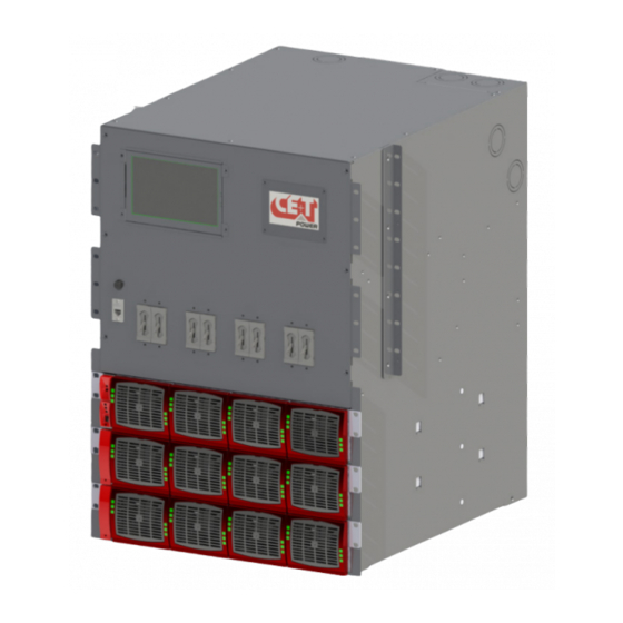
TSI REDUNDANT BRAVO SYSTEM
(RBS)-120 VAC
User Manual V7.0
BEYOND THE INVERTER
THE NEW GENERATION OF POWER CONVERTERS
DUAL INPUT INVERTER
The Commercial Power as default source
AC BACKUP IN A DC ENVIRONMENT
Leverage your existing DC infrastructure
ONE STOP SHOP
Wide output power range
HARSHEST AC INPUT CONDITIONS
Without compromising the quality of the AC output
Copyright © 2013. Construction electroniques & telecommunications S.A.
All rights reserved. The contents in document are subject to change without notice.
The products presented are protected by several international patents and trademarks.
Address: CE+T S.a, Rue du Charbonnage 12, B 4020 Wandre, Belgium
www.cet-power.com - info@cet-power.com
Important Safety Instructions
Save these Instructions
www.cet-power.com
Advertisement
Table of Contents
Troubleshooting

Subscribe to Our Youtube Channel
Related Manuals for CE+T Power RBS Series


Summary of Contents for CE+T Power RBS Series
- Page 1 TSI REDUNDANT BRAVO SYSTEM (RBS)-120 VAC User Manual V7.0 BEYOND THE INVERTER THE NEW GENERATION OF POWER CONVERTERS DUAL INPUT INVERTER The Commercial Power as default source AC BACKUP IN A DC ENVIRONMENT Leverage your existing DC infrastructure ONE STOP SHOP Wide output power range HARSHEST AC INPUT CONDITIONS Without compromising the quality of the AC output...
-
Page 2: Table Of Contents
Table of content 1. CE+T at a glance ..............................2. Abbreviations ................................3. Safety Instructions ..............................3.1 Disclaimer ................................ 3.2 Technical care ..............................3.3 Installation ................................ 3.3.1 Handling ............................... 3.3.2 Surge and transients ..........................3.3.3 Other ..............................3.4 Maintenance ..............................3.5 Replacement and Dismantling .......................... - Page 3 8.4.4 DC Input ............................... 8.4.5 Signalling Connection and Purpose ...................... 9. Human-Machine Interface ............................9.1 Inverter module ..............................9.2 T2S .................................. 9.3 Candis Interface ............................... 9.3.1 Installing Candis Display ........................9.3.2 Replacing Candis Display ........................9.4 Catena GUI Interface ............................9.4.1 Installing Catena GUI Interface ......................
- Page 4 Release Note: Release date Modified page Version Modifications (DD/MM/YYYY) number 16/03/2016 First release of the Manual. – RBS 120VAC– User manual – v7.0...
-
Page 5: Ce+T At A Glance
CE+T at a glance 1. CE+T at a glance CE+T Power designs, manufactures and markets a range of products for industrial operators with mission critical applications, who are not satisfied with existing AC backup systems performances, and related maintenance costs. -
Page 6: Abbreviations
Abbreviations 2. Abbreviations Twin Sine Innovation Enhanced Power Conversion Regular Digital Signal Processor Alternating current Direct current Electro Static Discharge Main Earth Terminal Manual By-pass TCP/IP Transmission Control Protocol/Internet Protocol Universal Serial Bus Protective Earth (also called Main Protective Conductor) Neutral Printed Circuit Board True Redundant Structure... -
Page 7: Safety Instructions
Safety Instructions 3. Safety Instructions Important safety instructions and save these instructions. 3.1 Disclaimer The manufacturer declines all responsibilities if equipment is not installed, used or operated according to instructions „ „ herein by skilled technician according to local regulations. „... -
Page 8: Installation
Safety Instructions 3.3 Installation „ „ Inverter System may contain output over current protection in the form of circuit breakers. In addition to these circuit breakers, the user must observe the recommended UL listed upstream and downstream circuit breaker requirements as defined in this manual. -
Page 9: Maintenance
Safety Instructions 3.4 Maintenance „ „ The modular inverter system/rack can reach hazardous leakage currents. Earthing must be carried out prior energizing the system. Earthing shall be made according to local regulations. „ „ Prior to any work conducted to a system/unit make sure that AC input voltage and DC input voltage are disconnected. „... -
Page 10: Tsi Technology
TSI TECHNOLOGY 4. TSI TECHNOLOGY Inverter modules carrying the TSI logo and the EPC mark are triple port converters (AC in, DC in, AC out). Sinusoidal output is converted from Mains or/and DC. The block diagram here below gives an explicit description of the topology and operation. BOOST L’... -
Page 11: Epc Mode
TSI TECHNOLOGY 4.1 EPC Mode „ „ Mains input (AC) is the primary source whilst DC works as backup. „ „ The TSI is designed to operate on Mains on permanent basis and to deliver output voltage conditioned with low THD. „... -
Page 12: Building Blocks
Building Blocks 5. Building Blocks 5.1 Inverter module Bravo: 110 VDC / 120 VAC, 60Hz. „ „ The TSI Bravo is a 2500VA/2000W triple port inverter. „ „ The TSI inverter modules are hot swappable and hot pluggable. „ „ The module operator interface is LEDs showing converter status and output power „... -
Page 13: Accessories
Accessories 6. Accessories 6.1 T2S Interface The T2S is an interface giving access to the TSI modules that are connected together in any TSI systems. The T2S doesn’t perform any control or management of the TSI system. It can be removed, replaced or moved to another live system without affecting neither the original TSI system operation nor the target system. -
Page 14: Catena
Accessories 6.2 Catena Catena GUI Interface is a powerful web based touch screen graphical display, it allows user to easily access and monitor the system. In addition to the touch screen display, user can also access to same GUI by using an Ethernet port which is present on the catena. Measures „... -
Page 15: Candis
Accessories 6.3 Candis The Candis is an optional interface allowing the user to get system running information on display. The definition settings available on Candis are voltages, currents, frequency, inverter configured, and so on. (Use a tip pen or a soft edge stick to push on buttons 2 , 3 or 4) Display (2 lines provided to display information). -
Page 16: Rbs Design And Description
RBS Design and Description 7. RBS Design and Description 7.1 System Design RBS is a cabinetized modular inverter specifically designed for clean and temperature controlled environments. Industrial grade design. „ „ Please refer to the technical For airflow, provisions are provided at Rear. „... -
Page 17: System Description
RBS Design and Description 7.2 System Description RBS comes fully equipped with „ „ DC individual branch protection is provided for each three modules connected vertically (UL 489A). T2S interface shall be 2C version (High Voltage) with USB/ETH. „ „ Surge Arresters. -
Page 18: Rbs Single Phase Configuration
RBS Design and Description 7.3 RBS Single Phase Configuration A single phase system is 120VAC from L to N. Input and output are the same, made upon 2 wires + (PE) Ground. Max Power Max number of System Designation Max power (KW) (kVA) Modules RBS-1-10-XX-04-1DC... -
Page 19: Rbs Split Phase Configuration
RBS Design and Description 7.4 RBS Split Phase Configuration A split phase system is 120VAC from L to N and 240VAC from L1 to L2 are phase shifted by 180 degree (upon request, it can also be 208VAC. L1, L2 are phase shifted by 120 degree). Input and output are made upon 3 wires + (PE) Ground, cabling and phase shift must match. -
Page 20: Rbs Three Phase Configuration
RBS Design and Description 7.5 RBS Three Phase Configuration A Three phase system is 120VAC from L to N and 208 VAC from L1 to L2, L1 to L3, L2 to L3. Input and output are made upon 4 wires + (PE) Ground, “Y” or “Star” connection. All phases are phase shifted by 120 degree one to the other. -
Page 21: Rbs Module Based Current Ratings
RBS Design and Description 7.6 RBS Module based Current Ratings Number of Rated AC Input/Output Current Rated DC Input Current Modules per Phase (Amps) (Amps) 120 Vac - Single Phase - 2 Wires + PE 20.83 20.20 41.65 40.40 62.48 60.60 83.30 80.80... -
Page 22: System Installation
System Installation 8. System Installation 8.1 Site Preparation „ „ Refer to section 7 to identify type of system and configurations. „ „ Input and output protections When installing RBS inverter systems, UL489 listed AC upstream (input) and downstream (output) circuit breakers are required. Output distribution should be structured to guarantee tripping segregation. -
Page 23: Unpacking The System
System Installation 8.2 Unpacking the system Modules are packed separately. They are normally marked to be replaced in the right slot (important for multi phase systems). Module packing material should be taken apart and stored in case of return under warranty. Unproper packing may void the warranty. -
Page 24: Cable Inlets
System Installation 8.4.1 Cable Inlets Use appropriate collar to fix the conduits to the cabinet ceiling. Use existing punch out to not block the airflow through the top of the cabinet. The ceiling can be split to facilitate the cabling. Knockout conduits for AC IN and OUT are same in dimension. -
Page 25: Ac Input And Output
System Installation Both PE (Protective Earth) is connected to Earthing Stud. It is factory wired and shall not be removed. 8.4.3 AC Input and Output The pictorial representation of terminal blocks arrangement is as follows. If AC IN is connected, remove the bonding neutral jumper cable between AC IN Neutral and PE terminal. –... - Page 26 System Installation AC input and AC output should be wired to connecting terminal blocks as per following indications: 8.4.3.1 Single Phase 8.4.3.2 Split Phase – RBS 120VAC– User manual – v7.0...
-
Page 27: Dc Input
System Installation 8.4.3.3 Three Phase 8.4.4 DC Input 8.4.4.1 Individual Feed DC Input It is mandatory to use only C-UL-US or CSA listed Cable Lugs. „ „ Individual DC connection. „ „ Note: Cable shoes are not included in the delivery. „... - Page 28 System Installation 8.4.4.2 Dual Feed DC Input „ „ It is mandatory to use only C-UL-US or CSA listed Cable Lugs. „ „ Dual DC connection. „ „ Note: Cable shoes are not included in the delivery. 5/ 1 6 ”...
-
Page 29: Signalling Connection And Purpose
System Installation 8.4.5 Signalling Connection and Purpose All relays are shown in non energized state. 8.4.5.1 Alarm (X3) „ „ Relay characteristics X3 (Major (UA), Minor(NUA), Prog) - Switching power - Rating 2A at 30VDC / 1A at 60VDC - Max wire size 17 AWG (1mm Relays are energized when idle and contacts are released when event occurs. - Page 30 System Installation 8.4.5.3 Remote ON/OFF (X6) Note: The system is by default equipped with a connection between pin 3 and 2. If remote ON/OFF is not used the strap shall remain. Should the remote ON/OFF be used the strap must be replaced with a changeover contact or emergency button. „...
-
Page 31: Human-Machine Interface
Human-Machine Interface 9. Human-Machine Interface 9.1 Inverter module Inverter Status LED Description Remedial action No input power or forced stop Check environment Permanent green Operation Converter OK but working conditions are Blinking green not fulfilled to operate properly Recovery mode after boost Blinking green/orange alternatively (10 In short circuit condition) Permanent orange... -
Page 32: Candis Interface
Human-Machine Interface 9.3 Candis Interface The Candis is an optional interface allowing the user to get system running information on display. The definition settings available on Candis are voltages, currents, frequency, inverter configured, and so on. The single display shows all parameters for the three phase system. Canbus ID, phase, and group information have to be changed manually. - Page 33 Human-Machine Interface Step 3: Remove the knock out. Step 4: Place the Candis protection cover at rear side of the closing plate. Step 5: Place the Candis display at front side of the closing plate and tight the both screws. Step 6: Connect the appropriate RJ45 cable to the Candis display from the system and place the closing plate into the slot.
-
Page 34: Replacing Candis Display
Human-Machine Interface 9.3.2 Replacing Candis Display Candis Display can be replaced into the system as per the following steps. Step 1: Unscrew all the four screws on the closing plate. Step 2: Disconnect the RJ45 cables in the Candis Display and remove the closing plate from the system. Step 3: Unscrew the both screws on the Candis Display and remove it from the closing plate. -
Page 35: Catena Gui Interface
Human-Machine Interface 9.4 Catena GUI Interface Catena GUI Interface is a powerful web based touch screen graphical display, it allows user to easily access and monitor the system. In addition to the touch screen display, user can also access to same GUI by using an Ethernet port which is present on the catena. -
Page 36: Replacing Catena Gui Interface
Human-Machine Interface 9.4.2 Replacing Catena GUI Interface Catena GUI Interface can be replaced into the system as per the following steps. Step 1: Unscrew all the four screws on the Catena GUI interface. Step 2: Disconnect appropriate cables in the Catena GUI Interface and remove it from the system. Step 3: Connect appropriate cable to the new Catena GUI Interface from the system and place it into the slot. -
Page 37: System Set Up
System set up 10. System set up RBS System is delivered with default set of parameters referred as factory settings. The standard supply will be represented as below: „ „ Candis with T2S USB „ „ Catena withT2S ETH **There is a possibility to have above configuration changed upon customer request. 10.1 T2S USB Upon various site operating conditions or Site Manager requirements some parameters might have to be adjusted. -
Page 38: Menu Access
System set up 10.1.2 Menu access Root Menu 1 > System configuration 0 > Return to previous menu 1 > Send config file to T2S 2 > Read config file from T2S 3 > Restore default settings (no more available since version 2.5) 4 >... -
Page 39: T2S Ethernet Via Catena
System set up 10.2 T2S Ethernet via Catena Once system is powered upon, the Catena is up and ready for operation. Configuration and other parameters can be changed using the Catena interface. 10.2.1 User GUI Interface Catena CATENA provides a quick and efficient user interface to: Get and overview of the system information „... - Page 40 System set up 10.2.1.1 CATENA Start up Applying start-up power – web interface Initiate the start-up routine by applying power to the CATENA NOTE: The controller will perform a short self-test as it boots up. Alarm alerts are normal. Use the touchscreen or connect the computer to the ETHERNET port and start your web browser. Point your browser to 192.168.0.2 (default address).
- Page 41 System set up 10.2.1.2 The Home page After connecting in basic or expert level the catena will display the home page below Tool bar to access to event, connections, files or parameters AC input menu display AC input power in kW AC output menu display level of AC output power in kW/kVA DC input menu System menu and further module menu...
- Page 42 System set up 10.2.1.3 The AC input page Click the Search button at AC input to obtain detail AC input information of the 3 phase Provide „ „ AC input voltage for each phase AC input current per phase „ „...
- Page 43 System set up 10.2.1.5 The AC output page Click the Search button at AC output to obtain detail AC output information Provide Graph indicating the level of power per phase „ „ AC output voltage for each phase „ „ AC output current per phase „...
- Page 44 System set up 10.2.1.6 The System page Click the Search button at the cabinet in the home page will bring you to the system page „ „ AC folder is related to the inverter module with detail per phase Number of module installed per phase „...
-
Page 45: The Toolbar
System set up 10.2.2 The TOOLBAR 10.2.2.1 Event At the bottom of the screen a permanent “Tool bar” populated with different button: Events present in the system the circled number indicate how many “active event” are present. The color indicate the severity of the event. Green is OK, Orange is Minor and Red is Major. Figure below gives list of active event /alarm Red is Major, Orange is Minor Click the Log button to access the log file which is a record of last 500 event with date and time the occurred in the... - Page 46 System set up Figure below show a screen of the log file. 10.2.2.2 Connections Click on Connections button to access the mapping of the digital inputs and relays output – RBS 120VAC– User manual – v7.0...
- Page 47 System set up 10.2.2.3 Files Click on Files to: „ „ Export the log file „ „ Clear the log file (only possible in expert mode) Upgrade the software of the CATENA supervisor „ „ – RBS 120VAC– User manual – v7.0...
-
Page 48: Switching Off Rbs System
System set up 10.2.2.4 Parameters To define and setup all communication parameter listed below Please do not change setting below unless necessary. 10.3 Switching OFF RBS System Perform the following steps to Switch OFF the RBS System. Caution: While switching OFF the RBS System, the power to load will be disconnected. Switch OFF AC Output Downstream Breakers. -
Page 49: Inserting/Removing/Replacing Modules
Inserting/removing/replacing modules 11. Inserting/removing/replacing modules 11.1 TSI Inverter „ „ The TSI inverter module is hot swappable. „ „ When a new module is inserted in a live system it automatically takes the working set of parameters. „ „ When a new module is inserted in a live system it is automatically assigned to the next available address. 11.1.1 Removal Notice: When one or several inverter modules is/are removed, live parts become accessible. -
Page 50: T2S
Inserting/removing/replacing modules 11.2 T2S 11.2.1 Removal Use a small screw driver to release the latch keeping the T2S in position. „ „ Pull the T2S out. „ „ 11.2.2 Inserting „ „ Push the T2S firmly in place until the latch snaps in position. 11.3 Fan replacement The FAN life is approx 45.000hours. -
Page 51: System Start-Up And Shut Down
System Start-up and Shut down 12. System Start-up and Shut down 12.1 Final Check „ „ Make sure that the sub-rack and slidings/cabinet is properly fixed to the cabinet/floor. „ „ Make sure that the sub-rack/cabinet is connected to Ground. Make sure that all DC and AC input breakers are switched OFF. -
Page 52: Start Up
System Start-up and Shut down 12.2 START UP „ „ Verify AC input/output and DC input connections. „ „ Verify Load is connected to output of inverter system. „ „ Switch ON the upstream DC supply. Verify presence of DC supply by using multimeter before closing the DC input breaker. „... -
Page 53: Commissioning
Commissioning 13. Commissioning The DC breaker is a protection device. Modules are plugged in a system and DC breaker is then engaged. Please make sure the corresponding DC breaker is engaged in the ON position. Failure to observe this rules will result not to have all module operating when running on DC and have module failure when AC input recover from fault condition. -
Page 54: Check List
Commissioning 13.1 Check list DATA Date Performed by Site System serial number Module serial numbers T1S/T2S serial number-Specify T1S/T2S ACTION OK/ N.OK Unplug all inverters except one inverter per phase (Just pull off the inverter from the shelf, to interrupt electrical contacts) Check the commercial AC before closing the AC input breaker. -
Page 55: Trouble Shooting And Defective Situations Fixing
Trouble Shooting and Defective Situations Fixing 14. Trouble Shooting and Defective Situations Fixing 14.1 Trouble Shooting Inverter module does not power up: Check AC input present and in range (AC breakers) Check DC input present and in range (DC breakers) Check that the inverter is properly inserted Remove inverter to verify that slot is not damaged, check connectors Check that module(s) is (are) in OFF state... -
Page 56: Defective Modules
The RMA number should be mentioned on all shipping documents related to the repair. „ „ Be aware that products shipped back to CE+T Power without being registered first will not be treated with high priority! Information on failure occurrence as well as module status given through Menu 2-1 shall „... -
Page 57: Service
Service 15. Service For Service „ „ Check Service Level Agreement (SLA) of your vendor. Most of the time they provide assistance on call with integrated service. If such SLA is in place, you must call their assistance first. If your vendor doesn’t provide such assistance (*) you may call CE+T directly. Toll free Number 1(855) 669 - 4627(**) „... -
Page 58: Maintenance Task
Maintenance Task 16. Maintenance Task As maintenance will be performed on live system, all tasks should be performed only by trained personnel with sufficient acknowledge on TSI product. Tasks : „ „ Identify the site, customer, rack number, product type. „...
Need help?
Do you have a question about the RBS Series and is the answer not in the manual?
Questions and answers