Table of Contents
Advertisement
Quick Links
TSI MIPS - 120 VAC
MODULAR INVERTER POWER SYSTEM
User Manual V7.5
BEYOND THE INVERTER
THE NEW GENERATION OF POWER CONVERTERS
•
DUAL INPUT INVERTER
Commercial Power as default source
•
AC BACKUP IN A DC ENVIRONMENT
Leverage your existing DC infrastructure
•
ONE STOP SHOP
Wide output power range
•
HARSHEST AC INPUT CONDITIONS
Without compromising the quality of the AC output
Copyright © 2013. Construction electroniques & telecommunications S.A.
All rights reserved. The contents in document are subject to change without notice.
The products presented are protected by several international patents and trademarks.
Address: CE+T S.a, Rue du Charbonnage 12, B 4020 Wandre, Belgium
www.cet-power.com - info@cet-power.com
Belgium, China, India, Luxembourg, Malaysia, Russia, United Kingdom, United States, Australia & Germany
www.cet-power.com
Advertisement
Table of Contents
Troubleshooting

Subscribe to Our Youtube Channel
Related Manuals for CE+T Power TSI MIPS 120 VA


Summary of Contents for CE+T Power TSI MIPS 120 VA
- Page 1 TSI MIPS - 120 VAC MODULAR INVERTER POWER SYSTEM User Manual V7.5 BEYOND THE INVERTER THE NEW GENERATION OF POWER CONVERTERS • DUAL INPUT INVERTER Commercial Power as default source • AC BACKUP IN A DC ENVIRONMENT Leverage your existing DC infrastructure •...
-
Page 2: Table Of Contents
Table of Contents 1. CE+T at a glance ........................... 2. Abbreviations ............................3. Warranty and Safety Conditions ......................Disclaimer ........................... Technical care ..........................Installation ..........................3.3.1 Handling ......................... 3.3.2 Surge and Transients Protection ..................3.3.3 Other ..........................Maintenance ..........................Replacement and Dismantling ..................... 4. - Page 3 MIPS Module Based Current Ratings ................... 8. System Installation ..........................Site Preparation ........................... 8.1.1 Transformer and Generator Sizing .................. Packaging Information ......................... Module packing ........................... Anchoring the cabinet to the floor ....................Cabling ............................8.5.1 Tightening Torque ......................8.5.2 Cable Inlets ........................8.5.3 Grounding ........................
- Page 4 15.2.2 Return defective T2S interface ..................15.2.3 Return defective shelf ....................15.2.4 Return defective modules ....................16. Service ..............................17. Maintenance Task ..........................– TSI MIPS - 120 VAC - User Manual - v7.5...
- Page 5 Release Note: Release date Modified page Version Modifications (DD/MM/YYYY) number 19/02/2014 First release of the Manual System description illustration (AC in & AC out representation changed) Cabinet inlets illustration (AC in & AC out location changed) 30/04/2014 Earth grounding and Neutral grounding illustration MBP section updated with content 6, 7, 11, 22, 32, 23/03/2015...
-
Page 6: Ce+T At A Glance
CE+T at a glance 1. CE+T at a glance CE+T Power designs, manufactures and markets a range of products for industrial operators with mission critical applications, who are not satisfied with existing AC backup systems performance and related maintenance costs. -
Page 7: Abbreviations
Abbreviations 2. Abbreviations Alternating current Circuit Breaker Direct current Digital Signal Processor Enhanced Power Conversion Electro Static Discharge Manual By-pass Miniature Circuit Breaker MCCB Molded Case Circuit Breaker Main Earth Terminal Neutral Non-Urgent Alarm Printed Circuit Board Protective Earth (also called Ground Conductor) Regular TCP/IP Transmission Control Protocol/Internet Protocol... -
Page 8: Warranty And Safety Conditions
Warranty and Safety Conditions 3. Warranty and Safety Conditions WARNING: The electronics in the power supply system are designed for an indoor, clean environment. When installed in a dusty and/or corrosive environment, indoors, it is important to: • Install an appropriate filter on the enclosure door, or on the room’s air conditioning system. Installation of filters may result in derating of module. -
Page 9: Installation
Warranty and Safety Conditions • When handling the system/units pay attention to sharp edges. • This product is suitable for use in a computer room. 3.3 Installation • This product is intended to be installed only in restricted access areas as defined by UL60950 and in accordance with the National Electric Code, ANSI/NFPA 70, or equivalent agencies. -
Page 10: Surge And Transients Protection
Warranty and Safety Conditions 3.3.2 Surge and Transients Protection The mains (AC) supply of the modular inverter system shall be equipped with Lightning surge suppression and Transient voltage surge suppression suitable for the application. Follow manufacturer’s recommendation for installation. Selecting a device with an alarm relay for function failure is advised. All sites are considered to have a working lightning surge suppression device in service and installed close enough to ensure effective protection in accordance with best industry practice. -
Page 11: Tsi Technology
TSI Technology 4. TSI Technology Inverter modules carrying the TSI logo and the EPC mark are triple port converters (AC in, DC in, AC out). Sinusoidal AC output is converted from the AC main source and/or the DC source. The block diagram below gives an explicit description of the topology and operation. BOOST L’... -
Page 12: Epc Mode
TSI Technology 4.1 EPC Mode • In EPC Mode, the AC Main source is the primary source while the DC source is secondary. • The TSI is designed to operate on the AC main source on a permanent basis and to deliver output AC voltage with low THD. -
Page 13: Inverter Components
Inverter Components 5. Inverter Components 5.1 Inverter module BRAVO: -48 VDC / 120 VAC, 60 Hz (50 Hz) 125 VDC / 120 VAC, 60 Hz (50 Hz) 380 VDC / 120 VAC, 60 Hz (50 Hz) Figure 1. TSI Bravo Module •... -
Page 14: Accessories
Accessories 6. Accessories 6.1 Monitoring - T2S ETH The T2S ETH is an interface giving access to the TSI modules that are connected together in any TSI systems. The T2S ETH doesn’t perform any control or management of the TSI system. It can be removed, replaced or moved to another live system without affecting the original TSI system operation nor the target system. -
Page 15: Catena
Accessories 6.2 CATENA The Catena GUI Interface is a powerful web based touch screen graphical display, it allows the user to easily access and monitor the system. In addition to the touch screen display, the user can also access the same GUI by using an Ethernet port which is present on the catena. -
Page 16: Candis
Accessories 6.3 CANDIS 6.3.1 CANDIS shelf Figure 7. Monitoring - CANDIS The CANDIS shelf has slots for up to 3 display units and 1 TCP/IP agent. 6.3.2 Display Backlit 2 line dot matrix. The display shows two values simultaneously. 6.3.3 TCP/IP Agent The TCP/IP interface board is mounted on the CanDis shelf and is powered from within the system. -
Page 17: Manual Bypass
Accessories 6.4 Manual Bypass The Manual Bypass operates via manually operated switches to create a connection from the AC main input directly to the output AC distribution. Standard Manual Bypass are “Make before Break”. When engaged or disengaged, no disturbance is transmitted to the load. When MBP is engaged, inverter modules are switched off and can be removed without impacting the load. -
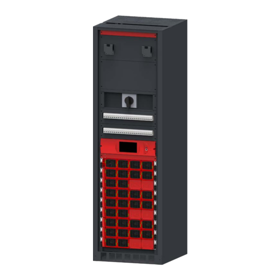
Page 18: Mips Design And Description
MIPS Design and Description 7. MIPS Design and Description 7.1 System Design MIPS is a cabinetized modular inverter specifically designed for clean and temperature controlled environments. • Telecom grade design. • Based on TSI BRAVO – 120 VAC Inverter Module. •... -
Page 19: System Description
MIPS Design and Description 7.2 System Description MIPS comes fully equipped with • Individual DC protection for modules. • MBP included by default (can be removed on request). • EMBS available upon request. • CATENA or CANDIS shelf and display (one display per phase configured). •... -
Page 20: Mips Single Phase Configuration - 120 Vac
MIPS Design and Description 7.3 MIPS Single phase configuration - 120 VAC A single phase system is 120 VAC from L to N. Input and output are the same, consisting of 2 wires + (PE) Ground. System Max Power Number of Max number of Max power (KW) Designation... -
Page 21: Mips Single Phase Configuration - 240 Vac
MIPS Design and Description 7.4 MIPS Single Phase Configuration - 240 VAC A split phase system is 120 VAC from L to N and 240 VAC from L1 to L2 and L1 and L2 are phase shifted by 180 degrees. (For 208 VAC systems, the phase shift can be set to 120 degrees). Input and output are made upon 3 wires + Ground, cabling and phase shift must match. -
Page 22: Mips Three Phase Configuration - 208 Vac
MIPS Design and Description AC input & AC output System Cable Max Based on Branch Protection Supplementary Protection Designation Breaker Cable Min Breaker Cable Min Terminal Size MIPS-2-20-xx-08 110 A 1 AWG 100 A 2 AWG 1 AWG MIPS-2-40-xx-16 225 A 250 kcmil 200 A 4/0 AWG... - Page 23 MIPS Design and Description Bulk DC input 2 DC input System Designation Fuse or Fuse or Cable Min (per Cable Max Cable Min Cable Max Breaker Breaker feed) (per feed) MIPS-3-75-xx-30 6 x 500 MCM or 9 x 500 2 x 500 2000 A 3 x 600 A 2 x 500 MCM...
-
Page 24: Mips Module Based Current Ratings
MIPS Design and Description 7.6 MIPS Module Based Current Ratings Rated AC Input / Rated DC (48V) Rated DC (125V) Rated DC (380V) # Modules Output Current per Input Current per Input Current per Input Current per Phase (Amps) Polarity (Amps) Polarity (Amps) Polarity (Amps) 120 Vac –... -
Page 25: System Installation
System Installation 8. System Installation 8.1 Site Preparation • Input and output protection. When installing MIPS inverter systems, UL489 listed AC upstream (input) and downstream (output) circuit breakers are required. Refer Section 7.3, page 20, 7.4, page 21, and 7.5, page 22 for breaker sizes. At MIPS Input Branch circuit protection breaker should be provided in upstream switchgear regardless of any protective device already installed at the input of the MIPS. -
Page 26: Transformer And Generator Sizing
System Installation 8.1.1 Transformer and Generator Sizing The inverter is capable of operating at 150% of rated capacity for 15 seconds. The boost function allows up to 10 times the rated inverter capacity for 20 ms to clear downstream faults. •... -
Page 27: Anchoring The Cabinet To The Floor
System Installation 8.4 Anchoring the cabinet to the floor The cabinet is anchored through the base of the cabinet. Remove lowest front cover to get access to the anchoring locations. Max screw diameter is 0.8” (22 mm). See Hole pattern, foot print. For foot print measurements. Figure 15. -
Page 28: Cable Inlets
System Installation 8.5.1.2 DC Connections (per NEC) Size of wire Tightening Torque [AWG/kcmil] 2 - 1 16.9 1/0 - 2/0 20.3 3/0 - 4/0 28.2 250 - 350 36.7 42.4 8.5.2 Cable Inlets Use appropriate conduit fitting to attach the conduits to the top of the cabinet. Use existing knock outs and do not block the airflow through the top of the cabinet. -
Page 29: Ac Input And Output
System Installation Note: Connection in yellow-green are factory wired and shall not be removed. (In the below image the connection is shown in green color). Figure 18. Earthing connections 8.5.4 AC Input and Output The pictorial representation of terminal blocks arrangement is as follows. Note: If AC IN is connected, remove the Neutral bonding jumper cable between X2 (AC IN) and frame ground. -
Page 30: Dc Input
System Installation AC input and AC output shall be wired to connecting terminal blocks as per following indications: Single Phase Split Phase Three Phase When connecting AC input and output cables, you must remove the washer from the terminal block prior to landing the cable lug. Reinstall the washer between the cable lug and the nut. - Page 31 System Installation 8.5.5.2 Dual DC Feed Input • 2 x DC input connection per system. • Two holes of ” threaded hole with 1”(25.4 mm) between center. • Internal DC distribution with circuit breakers (Q01-Q30) to each inverter module. • Max 3 x 500 kcmil (240 mm ) per pole (group).
- Page 32 System Installation 8.5.5.3 Dual DC Feed - Internal Wiring Pattern – TSI MIPS - 120 VAC - User Manual - v7.5...
- Page 33 System Installation 8.5.5.4 Triple DC Feed Input • 3 x DC input connection per system. • Two holes of ” threaded hole with 1”(25.4 mm) between center. • Internal DC distribution with circuit breakers (Q01-Q32) to each inverter module. • Max 2 x 500 kcmil (240 mm ) per pole(group).
- Page 34 System Installation 8.5.5.5 Triple DC Feed Input - Internal Wiring Pattern – TSI MIPS - 120 VAC - User Manual - v7.5...
-
Page 35: Signaling
System Installation 8.5.6 Signaling All relays are shown in non energized state. Figure 26. Alarm dry contacts Note: Output relays are time delayed factory default set to 30 seconds, User settable from 2 to 30 seconds. To connect “Inverter in Bypass” status signal from inverter to External Manual Bypass (MBP) Switch, connect external MBP to X3 terminals 7 and 9. -
Page 36: Switching Off Mips System
System Installation 8.5.6.3 Remote ON/OFF (X6) Note: The system is by default equipped with a connection between pin 3 and 2. If remote ON/OFF is not used the strap shall remain. Should the remote ON/OFF be used the strap must be replaced with a changeover contact or emergency button. -
Page 37: Human-Machine Interface
Human-Machine Interface 9. Human-Machine Interface 9.1 Inverter module AC OUT DC IN AC IN Inverter Status Output Power Status Inverter Status LED Description Remedial action No input power or forced stop Check environment Permanent green Operation Converter OK but working conditions are Blinking green not fulfilled to operate properly Recovery mode after boost... -
Page 38: T2S Eth
Human-Machine Interface 9.2 T2S ETH • Alarm indication on Catena (Urgent / Non Urgent / Configurable) - Green: No alarm - Red: Alarm - Flashing Exchanging information with inverters (only Configurable alarm) Micro SD Card Major Alarm • Outgoing alarm relay delay time Minor Alarm - Major and Minor Adjustable from 2 to 60 seconds... - Page 39 Human-Machine Interface 9.3.1.1 Catena Start up Initiate the start-up routine by applying power to the Catena. Note: The controller will perform a short self-test as it boots up. Alarm alerts are normal. Since Catena software v4.4.0, units equipped with a front RJ45 port; set computer to “obtain IP automatically” and direct web-browser to http://catena.local (don’t forget the dot).
- Page 40 Human-Machine Interface 9.3.1.2 The Home page After connecting at the basic or expert level, the catena will display the home page as below. Figure 30. Catena – Home page details Toolbar provides access to events, connections, files, and parameters AC input menu display AC input power in kW AC output menu display the level of AC output power in kW/kVA DC input menu System menu and further module menu...
- Page 41 Human-Machine Interface 9.3.1.3 The AC input page Click the Search button at AC input to obtain detail AC input information of the 3 phases: This screen provides the following information: • AC input voltage for each phase • AC input current per phase •...
- Page 42 Human-Machine Interface 9.3.1.5 The AC output page Click the Search button at AC output to obtain detail AC output information Figure 33. Catena – AC output page This screen provides the following information: • Graph indicating the power per phase of N (Not N+1), system capacity calculation does not include redundant modules.
- Page 43 Human-Machine Interface 9.3.1.6 The System page Click the Search button at the cabinet in the home page will bring you to the system page where following information can be found: System level: • Installed power - It is the total power of the configured modules, including redundancy.
-
Page 44: Toolbar
Human-Machine Interface Module Page This page gives the module by module measurement. T2S ETH is the monitoring solution for inverters, which are all single phase module. Many controls are available from this page to manage the module: The T° probe is the average T° of the inverter module heat sink Figure 36. - Page 45 Human-Machine Interface 9.3.2.2 Log Click the Log button to access the log file. It displays the list of last 2000 events with date and time stamps. Compared to the event page, an extra column is displayed if the event has appeared or disappeared. For each event, there are two log lines: one with the timestamp of the event appearing and the second one with the timestamp of the event disappearing.
- Page 46 Human-Machine Interface 9.3.2.5 Parameters The Parameters page is divided into tabs which are a compound of sub menus: • Monitoring • Input/Relays • SNMP • Modbus • Power • Info Figure 42. Catena – Parameters page (Note: To know more details about parameters section, refer T2S ETH user manual.) –...
-
Page 47: Unit - Inserting/Removing/Replacing
Unit - Inserting/removing/replacing 10. Unit - Inserting/removing/replacing 10.1 TSI Inverter Module • When a new module is inserted in a system, it is automatically assigned the configuration file from the existing modules or from the T2S-ETH. • When a new module is inserted in a system, it is automatically assigned to the next available address. 10.1.1 Removal Note: When one or several inverter modules is/are removed, live parts become accessible. -
Page 48: T2S Eth
Unit - Inserting/removing/replacing 10.2 T2S ETH T2S ETH is hot-swappable. It can be removed or replaced without affecting the operation of the system. If a new T2S ETH is inserted in the live system, the modules will automatically configure the system parameters within the T2S ETH. 10.2.1 Removal 1. -
Page 49: Fan Replacement
Unit - Inserting/removing/replacing 10.3 Fan replacement The fan’s life is approximately 60,000 (Sixty thousand) hours. The inverter modules have fan runtime meters and fan failure alarm. Fan failure can result from the failing fan or driver circuit. • Let the module rest at least five minutes before initiating work. •... -
Page 50: Manual Bypass Operation
Manual Bypass Operation 11. Manual Bypass Operation • Manual Bypass has to be operated by trained personnel only. • When system is in Manual Bypass the load is connected to AC main voltage without filtering. • An MBP Engaged output alarm will occur when the system is in Manual Bypass. •... -
Page 51: Bypass To Normal, Disengage Mbp
EMBS 11.2.2 Bypass to Normal, Disengage MBP 1. Turn switch to INTERIM (mid position). 2. PAUSE: Wait until the inverter modules have come to full operation and have synchronized (30-60seconds). The Top-Left LED on each module should be Green prior to proceding. 3. -
Page 52: Final Check
Final Check 13. Final Check • Make sure that the sub-rack and cabinet is properly anchored to the cabinet/floor. • Make sure that the sub-rack/cabinet is connected to Ground. • Make sure that all DC and AC input breakers are switched OFF. •... -
Page 53: Commissioning
Commissioning 14. Commissioning The inverter module DC input breaker acts as a protective device. When the modules are inserted into a system the DC breaker can then be turned ON to activate the DC input of the module. Installation must be performed by competent qualified employees. Commissioning and startup must be performed by any personnel who have been duly trained and possess a valid (non-expired) trainee ID certification number. -
Page 54: Trouble Shooting
Trouble shooting 15. Trouble shooting 15.1 Trouble shooting Inverter module does not power up: Check AC input present and in range (AC breakers) Check DC input present and in range (DC breakers) Check that the inverter is properly inserted Remove inverter to verify that slot is not damaged, check connectors Check that module(s) is (are) in OFF state Check for loose terminations Inverter system does not start:... -
Page 55: Defective Modules
Repair registering guidelines may be requested by email at repair@cet-power.com. • The RMA number should be mentioned on all shipping documents related to the repair. • Be aware that products shipped back to CE+T Power without being registered first will not be treated with high priority! •... -
Page 56: Service
Service 16. Service For Service • Check Service Level Agreement (SLA) of your vendor. Most of the time they provide assistance on call with integrated service. If such SLA is in place, you must call their assistance first. • If your vendor doesn’t provide such assistance (*) you may call CE+T directly. Toll free Number 1(855) 669 - 4627(**) Service is available from 8:00 A.M. -
Page 57: Maintenance Task
Maintenance Task 17. Maintenance Task As maintenance can be performed on live system, all tasks should be performed only by trained personnel with sufficient knowledge on TSI products. Tasks : • Identify the site, customer, rack number, product type. • Download and save the configuration file for back up. •...
Need help?
Do you have a question about the TSI MIPS 120 VA and is the answer not in the manual?
Questions and answers