Table of Contents
Advertisement
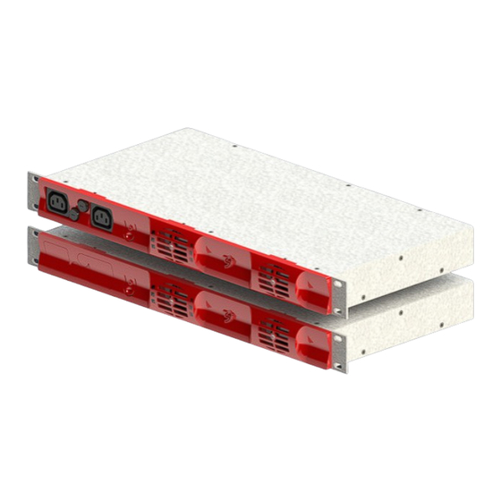
TSI Y-ONE - 230VAC
User Manual V7.4
BEYOND THE INVERTER
THE NEW GENERATION OF POWER CONVERTERS
DUAL INPUT INVERTER
The Commercial Power as default source
AC BACKUP IN A DC ENVIRONMENT
Leverage your existing DC infrastructure
ONE STOP SHOP
Wide output power range
HARSHEST AC INPUT CONDITIONS
Without compromising the quality of the AC output
Copyright © 2013. Construction electroniques & telecommunications S.A.
All rights reserved. The contents in document are subject to change without notice.
The products presented are protected by several international patents and trademarks.
Address: CE+T S.a, Rue du Charbonnage 12, B 4020 Wandre, Belgium
www.cet-power.com - info@cet-power.com
www.cet-power.com
Advertisement
Table of Contents

Related Manuals for CE+T Power TSI Y-ONE Series


Summary of Contents for CE+T Power TSI Y-ONE Series
- Page 1 TSI Y-ONE - 230VAC User Manual V7.4 BEYOND THE INVERTER THE NEW GENERATION OF POWER CONVERTERS DUAL INPUT INVERTER The Commercial Power as default source AC BACKUP IN A DC ENVIRONMENT Leverage your existing DC infrastructure ONE STOP SHOP Wide output power range HARSHEST AC INPUT CONDITIONS Without compromising the quality of the AC output Copyright ©...
-
Page 2: Table Of Contents
Table of contents 1. CE+T at a glance ........................... 2. Abbreviations ............................3. Warranty and Safety Conditions ......................Handling ............................Surge and transients ........................Other ............................4. TSI TECHNOLOGY ..........................On-line Mode ..........................Safe mode ..........................EPC-mode ........................... 5. Description ............................Typical load .......................... - Page 3 12. Trouble shooting............................ 13. Maintenance ............................13.1 Manual check ..........................13.2 Optional ............................13.3 Manual by-pass .......................... 14. Defective modules ..........................15. Appendix ............................... 15.1 Single phase circuit diagram ....................... – TSI Y-One 230 VAC – User manual – v7.4...
- Page 4 Release Note: Release date Modified Version Modifications (DD/MM/YYYY) page number 02/05/2013 First release of the Manual. 18/08/2014 10 and 15 IEC socket fuse details 11/01/2016 Fan replacement procedure 25/09/2017 Added REG mode features information (where applicable). 21/12/2017 Relay details – TSI Y-One 230 VAC – User manual – v7.4...
-
Page 5: Ce+T At A Glance
CE+T at a glance 1. CE+T at a glance CE+T Power designs, manufactures and markets a range of products for industrial operators with mission critical applications, who are not satisfied with existing AC backup systems performances, and related maintenance costs. -
Page 6: Abbreviations
Abbreviations 2. Abbreviations Twin Sine Innovation Enhanced Power Conversion Regular Digital Signal Processor Alternating current Direct current Electro Static Discharge Main Earth Terminal Manual By-pass TCP/IP Transmission Control Protocol/Internet Protocol Universal Serial Bus Protective Earth (also called Main Protective Conductor) Neutral Printed Circuit Board True Redundant Structure... -
Page 7: Warranty And Safety Conditions
Warranty and Safety Conditions 3. Warranty and Safety Conditions WARNING: The electronics in the power supply system are designed for indoor, clean environment. When installed in dusty and/or corrosive environment, outdoor or indoor, it is important to: • Install an appropriate filter on the enclosure door, or on the room’s air control system •... -
Page 8: Handling
Warranty and Safety Conditions • The safety standard IEC/EN62040-1-1 requires that, in case of output short circuit, the inverter must disconnect in maximum 5 seconds. However, if the parameter is set at a value > 5 seconds, an external protection must be provided in order that the short circuit protection operates within 5 seconds. -
Page 9: Tsi Technology
TSI TECHNOLOGY 4. TSI TECHNOLOGY Inverter modules carrying the TSI logo and the EPC mark are triple port converters (AC in, DC in, AC out). Sinusoidal output is converted from Mains or/and DC. The block diagram here below gives an explicit description of the topology and operation. The module is built around the following sub-converters •... -
Page 10: On-Line Mode
TSI TECHNOLOGY 4.1 On-line Mode DC is the primary source of supply whilst Mains (AC) works as the secondary source of supply. Switching time between DC input and AC input is 0 ms (source transfer).The power delivered by the DC source (usually a battery, but it could be any other type of DC generator) is converted to provide regulated and transient free power to the load. -
Page 11: Description
Description 5. Description TSI Y-One is a standalone Inverter with following capacities • Standalone model 1500 VA* • Standalone model 800 VA** • Standalone model 500 VA** 230Vac and 48Vdc as Input and 230Vac as Output fitted with Enhanced Power Conversion (EPC) mode * EPC model ** EPC and REG model TSI Y-One comes with two possible output configurations as follows. -
Page 12: Typical Load
Description 5.1 Typical load • Resistive • Inductive and resistive • Capacitive and resistive • Non linear load with a maximum crest factor of 2.5 for Y-One – TSI Y-One 230 VAC – User manual – v7.4... -
Page 13: Installation
Installation 6. Installation System is designed for installation in an IP20 or IP21 environment. When installed in a dusty or humid environment, appropriate measures (air filtering …) must be taken. The Y-One is foreseen to be recessed into an electrical cabinet of 19” and 1U height standard. Product weight is 9 Lbs (4 kg) 6.1 Y-One dimensions –... -
Page 14: Mounting Kit
Installation 6.1.1 Mounting KIT Make sure that you have received the right accessories for Y-One which consist 4 number of M6 x 16 mm Screws with spring and plate washer. 6.1.1.1 Mounting steps: STEP A: Insert the Y-One module inside the cabinet horizontally. STEP B: Fix the brackets and slider on the frame, using supplied bolts. -
Page 15: Wiring
Installation 6.2 Wiring Caution: The TSI Y-One has internal fuses on both DC & AC inputs. Those devices do not protect the upstream cables connected to DC & AC inputs and upstream breakers or fuses shall be set up in accordance with AC & DC wires ratings, to meet the local national electrical code standard. -
Page 16: Disconnecting And Protecting Devices
Installation NOTE: In REG models, AC IN connector will not be present, this location is covered with a mechanical part. This mechanical part should not be removed. In both Y-One EPC and Y-One REG models: • DC and AC conductors connected to screw terminals must be tied with torque between 1.2 and 1.5 Nm. •... - Page 17 Installation 6.2.3.3 Ferrite core connection Wind 2 turn of AC input phase and neutral on supply TUBE FERRITE (17.5x9.5x28.5 AL=2790 VHF EMC *WURTH ELEC 742 700 9*) as shown in figure. Ensure the core is near to the inverter backside. Note: Ferrite core correction is not applicable in REG models.
- Page 18 Installation 6.2.3.5 Replacing Fast Acting Fuse Incase Fast Acting Fuse Failure, perform the following steps to replace Fast Acting Fuse. Fast Acting fuse will be present at front left side of the system. Step 1: By using the Flat Screw Driver gently turn the Fuse holder to 45°...
-
Page 19: Grounding
Installation 6.2.4 Grounding Caution: Current leakages can reach hazardous values. For your personal, SAFETY earth connections must be done before energizing the system. Earth connection must be done to the point referenced with symbol Input ground must be connected to the appropriate terminal 6.2.5 Remote Monitoring and Control 6.2.5.1 Alarm Connector There are 2 free potential changeover contacts provided. - Page 20 Installation 6.2.5.2 Remote ON/OFF TSI system can be remotely activated or stopped (stand-by mode). Changeover contacts must be used. For transition the TSI checks actually that one input is released whilst the other is short circuited. If both transitions are not picked up the inverter does not change its operating status. The voltage present on terminal 1 and 3 is +5V (galvanically insulated).
-
Page 21: Dipswitch Configuration
Installation 6.2.6 Dipswitch configuration TSI Y-One has a facility to select the output voltage and frequency. Vout / Hz Selector has four mini switches. First and second switches are for voltage selection and third switch is for frequency selection. Fourth switch is for EPC / ONLINE mode selection. This functionality is explained below Caution: Do not configure or change the Vout / Hz / EPC Selector while module... -
Page 22: Manual By-Pass
Manual By-Pass 7. Manual By-Pass Manual By-Pass has to be operated by trained people only. When system is in manual by-pass the load is subjected to mains voltage without active filtering. Output alarm when system is in manual by-pass. The manual by-pass is not possible to operate remotely. Manual By-Pass is optional and must be ordered seperately. -
Page 23: Getting Started
Getting started 8. Getting started 8.1 Starting procedure Check that both AC input and output breakers are switched off. Apply the DC and/or AC power to the system. Push on the ON/OFF front touch to start the inverter. Output voltage should present on terminal or IEC socket. Check that system is operating under normal conditions. -
Page 24: Led Indication- Alarm Status
Getting started 8.3 LED indication- Alarm status LED AC/DC (in)* LED DC/DC (in) LED DC/AC (out) Status LED Description Alarm Description Alarm Description Alarm Source not Source not Minor Major Forced Stop Major present. present. Permanent Working fine no alarm Working fine no alarm Working fine... -
Page 25: Fan Replacement
Getting started 8.5 Fan Replacement The FAN pre-alarm “FAN life elapse” has been set to 5 years. The FAN alarms appear with the 3 LEDs status DC, AC, OUT flashing red for every 5 seconds. Perform the following steps to replace the fan: 1. -
Page 26: Finishing
Finishing 9. Finishing • Make sure that the inverter is properly fixed to the cabinet/floor. • Make sure that the inverter is connected to Ground. • Make sure that all DC and AC input breakers are switched OFF. • Make sure that all cables are according to recommendations and local regulations. •... -
Page 27: Disassembly & Disposal
Disassembly & Disposal 10. Disassembly & Disposal 10.1 Disassembly Switch off the upstream and downstream protective elements to stop the function of Inverter system. • Disconnect the wires from the terminals. • Ensure that all the cables (including PE, communication etc) are removed. •... -
Page 28: Commissioning
Commissioning 11. Commissioning The DC breaker is a protection device. When modules are plugged in a system please make sure the corresponding DC breaker is engaged in the ON position. Failure to observe this rules will result not to have all module operating when running on DC and have module failure when AC input recover from fault condition. -
Page 29: Check List
Commissioning 11.1 Check list DATA Date Performed by Site Inverter serial number ACTION OK/ N.OK Check the commercial AC before closing the AC input breaker. Switch ON the commercial AC Check if inverters are working (Green led) Check the DC power supply and switch ON the DC breakers Check output voltage (on bulk output or on breaker) Check if inverter is working properly Check if system has no alarm... -
Page 30: Trouble Shooting
Trouble shooting 12. Trouble shooting Inverter does not power up: Check that the inverter terminals are properly connected. Check AC input present and in range (AC breakers) Check DC input present and in range (DC breakers) Check for loose terminations Inverter does not start: Check remote ON/OFF terminal Check that Manual By-pass is in normal position... -
Page 31: Maintenance
Maintenance 13. Maintenance Maintenance shall only be performed by properly trained people. 13.1 Manual check • Validate input voltage (AC input, DC input, AC output) with multi-meter • Replace dust filter(if present) • Take a snap shot of the inverter 13.2 Optional •... -
Page 32: Defective Modules
• The RMA number should be mentioned on all shipping documents related to the repair. • Be aware that products shipped back to CE+T Power without being registered first will not be treated with high priority! (Label shown here is only for representation) -
Page 33: Appendix
Appendix 15. Appendix 15.1 Single phase circuit diagram – TSI Y-One 230 VAC – User manual – v7.4...
Need help?
Do you have a question about the TSI Y-ONE Series and is the answer not in the manual?
Questions and answers