Advertisement
Quick Links
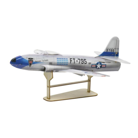
P-80 Shooting Star
Assembly Instructions
Important Instructions
1.The model is supplied with UFO and 502 glue. UFO is for bonding foam parts, and 502 for
bonding wood, carbon fiber and metal parts. 502 glue will cause serious corrosion to foam parts.
2.Please wait for the glue to dry and solidify in each installation step before the next installation.
3.Please avoid using flame to heat the heat shrinkable tube on the model. Electric iron shall be
used for heating.
4.Please use razor blade to remove the parts from the plate. Do not tear the parts by forc e.
Advertisement

Related Manuals for MinimumRC P-80 Shooting Star


Summary of Contents for MinimumRC P-80 Shooting Star
- Page 1 P-80 Shooting Star Assembly Instructions Important Instructions 1.The model is supplied with UFO and 502 glue. UFO is for bonding foam parts, and 502 for bonding wood, carbon fiber and metal parts. 502 glue will cause serious corrosion to foam parts.
- Page 2 1. Wooden display rack. 2. Fuselage wooden frame parts and printed components. 3. Assemble the fuselage wooden frame parts and printed components.
- Page 3 4. Install wooden beam. 5. Install the servos (top view of the parts). 6. Install the servos (bottom view of the parts).
- Page 4 7. Duct components. Install the propeller by applying force at the center of the motor's bottom cover to avoid damaging the motor. Ensure that the propeller is fully seated and secured in place. 8. Assemble the motor with the duct printed part, adjusting the motor installation depth to ensure the propeller blades are as close to the support as possible and rotate freely (insufficient proximity can significantly affect thrust).
- Page 5 9. Connect the ESC and servos to the receiver. Bind the receiver to the transmitter to ensure the servos are functioning properly. 10. Install the servo arms in the direction shown in the diagram. 11. Remove the two adjacent arms of a cross-shaped arm (as shown in the diagram).
- Page 6 12. Install the servo arms onto the aileron ser vo (As shown in the diagram). 13. Connect the motor wires and power up to test if the motor rotates in the correct direction.
- Page 7 15. Use a sharp tool (screwdriver) to score through the marked lines on the inner surface of the fuselage. Caution: when performing these operations, make sure to press on the part closest to the engraving lines to avoid tearing the components (as shown in the diagram).
- Page 8 18. Install the foam panel part on the bottom of the fuselage. 19. Install fuselage patch. 20. Combine the fuselage.
- Page 9 21. Install air inlet print. 22. Magnets and its supporting structure. 23. Install the magnetic assembly according to the diagram.
- Page 10 24. Apply the fuselage bottom sticker. 25. Apply the fuselage top sticker and the air inlet stickers. 26. Batter y compartment cover and magnet. Seal the circular hole on the batter y compartment cover with a sticker.
- Page 11 27. Install the battery compartment cover and magnet. 28. Apply the nose sticker, adhesive is needed here. 29. Use the nose sticker to connect the batter y compartment cover. The sticker needs to be fixed with adhesive. The battery compartment cover can be opened for ward and held in the closed position by a magnet.
- Page 12 30. Install wing support components. 31. Use a sharp tool (a screwdriver) to score along the marked lines on the bottom side of the wings at an angle. This allows the wings to bend downward along the central longitudinal line, forming an airfoil shape.
- Page 13 32. Use a sharp tool (a screwdriver) to score along the marked lines on the bottom side of the ailerons at an angle. This allows the ailerons to move up and down along the cut lines. 33. Use a sharp tool (a screwdriver) to score along the marked line on the right side of the vertical stabilizer at an angle.
- Page 14 34. Use a sharp tool (a screwdriver) to score along the marked lines on the bottom surface of the horizontal stabilizer at an angle. This allows the elevators to move freely along the cut lines. 35. Horizontal tail, vertical tail, and 1×90mm carbon rod. 36.
- Page 15 37. Paste a 1x90mm carbon fiber rod on the bottom of the horizontal stabilizer for reinforcement. 38. Install the tail. 39. Paste a 1x140mm carbon fiber rod on the bottom of the wing as a support strut.
- Page 16 40. Install the wings. A small amount of CA glue (502 glue) can be applied at the root of the wings and where the wings meet the spar to increase strength. 41. Install the vertical stabilizer control horn. 42. Install the horizontal stabilizer control horns.
- Page 17 43. Install the aileron control horns. 44. Open the access hatch cover. 45. Take a 1x125mm carbon rod for use as the rudder pushrod. Cut two pieces of heat shrink tubing, each 5mm in length, to connect the rudder pushrod and the wire clips.
- Page 18 46. Use heat shrink tubing to connect the pushrod and the wire clip, then apply a drop of CA glue (502 glue) to secure them. 47. Install the linkage hook onto the rudder control horn. 48. Insert the push rod and wire clip into the fuselage and attach them onto the rudder servo arm.
- Page 19 49. Detail: attach the clip onto the rudder servo arm. Use tweezers to operate here. 50. Use heat shrink tubing to connect the rudder pushrod and the linkage hook, then apply a drop of CA glue (502 glue) to secure them. 51.
- Page 20 52. Use heat shrink tubing to connect the pushrods and the wire clips, then apply a drop of CA glue (502 glue) to secure them. 53. Install the linkage hooks onto the horizontal stabilizer control horns. 54. Insert the carbon rods and wire clips into the fuselage, and install them onto the same hole on the elevator servo arm.
- Page 21 55. Use heat shrink tubing to connect the horizontal stabilizer pushrods and the linkage hooks, then apply a drop of CA glue (502 glue) to secure them. 56. Take two 1x75mm carbon rods for use as aileron pushrods. Cut four pieces of heat shrink tubing, each 5mm in length, to connect the aileron pushrods and the wire clips.
- Page 22 58. Install the linkage hooks onto the aileron control horns. 59. Insert the carbon rods and wire clips into the fuselage, then attach them onto the aileron servo arms. 60. Use heat shrink tubing to connect the aileron pushrods and the linkage hook, then apply a drop of CA glue (502 glue) to secure them.
- Page 23 61. Apply the access hatch cover panel sticker. 62. Follow the diagram to trim away the excess material from the cockpit canopy vacuum-formed part. It's advisable to start with conser vative cutting, place the canopy on the fuselage for alignment, and then make precise adjustments. 63.The trimmed cockpit canopy.
- Page 24 64. Use glue to secure the cockpit canopy in place on the corresponding position of the fuselage. 65. Apply the cockpit stickers. 66. Place the battery inside the nose.
- Page 25 Assembly complete! Maiden flight ·The center of gravity of the aircraft is located 5mm in front of the wing scored line. · When using the original electronic equipment of this model, three counterweight iron plate needs to be installed on the nose. ·The active range of ailerons, elevator and rudder are 4mm on both sides.
Need help?
Do you have a question about the P-80 Shooting Star and is the answer not in the manual?
Questions and answers