Advertisement
Quick Links
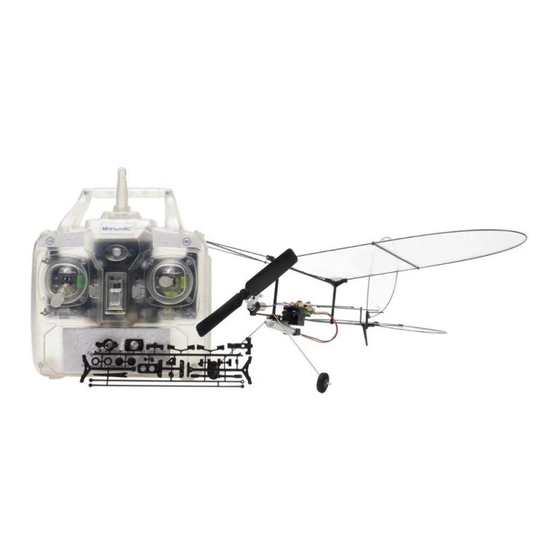
Butterfly T1-2024
Assembly Instructions
Important Instructions
1.The model is supplied with UFO and 502 glue. UFO is for bonding foam parts, and 502 for bonding
wood, carbon fiber and metal parts. 502 glue will cause serious corrosion to foam parts.
2.Please wait for the glue to dry and solidify in each installation step before the next installation.
3.Please avoid using flame to heat the heat shrinkable tube on the model. Electric iron shall be used
for heating.
4.Please use razor blade to remove the parts from the plate. Do not tear the parts by forc e.
Assembly techniques
Cut off the connector shown in the diagram and remove the part.
·
Advertisement

Related Manuals for MinimumRC Butterfly T1-2024


Summary of Contents for MinimumRC Butterfly T1-2024
- Page 1 Butterfly T1-2024 Assembly Instructions Important Instructions 1.The model is supplied with UFO and 502 glue. UFO is for bonding foam parts, and 502 for bonding wood, carbon fiber and metal parts. 502 glue will cause serious corrosion to foam parts.
- Page 2 Rotate to cut the carbon rod. · cut φ 0.8mm carbon rod into: 425mm - - - -2 pieces (for wings) · 300mm - - - -1 pieces (for Vertical tail) 550mm - - - -1 pieces (for Horizontal tail)
- Page 3 1. Fuselage component B C D and 1.5mm x250mm carbon rod. 2. Combination fuselage components B C D and 1.5mm x250mm carbon rod. Note that the higher part B is located at the front end of the fuselage, 25mm away from the end of the carbon rod.
- Page 4 4. Install two m1x3 screws at the front end of component B to secure the landing gear steel wire. 5. Tail base component M T Q. 6. The side of Component Q with the groove should face downwards. Insert component T into the circular hole of component Q and fix it with glue.
- Page 5 7. Install the assembled tail base assembly at the tail of the aircraft and fix it with glue. Please ensure that the component is completely horizontal during installation. The model can be placed on a plane for checking its level. 8.
- Page 6 10. Component P and gear components. 11. Note that the installation hole at the lower end of component P is inclined, and it will be installed on the body in a tilted downward manner, forming a tension line pull angle. Combination powertrain components, use glue to fix the motor and brass shaft sleeve, ensuring that the motor gear is properly engaged with the main gear.
- Page 7 13. Wheel parts J K and sponge tire. 14. Combination of wheels. 15. Install the wheels at the end of the landing gear steel wire.
- Page 8 16. Cut a 3mm length heat shrink tube and place it at the end of the steel wire. Heat shrink and fix it with adhesive to prevent the wheel from falling off. 17. Install the equipment base in the middle section of the fuselage. 18.
- Page 9 19. Take one 0.8x300mm carbon fiber rod for making vertical tail. Vertical tail component H E. 20. Fix the carbon fiber rod onto component H. The end of the carbon fiber rod should extend at least 10mm beyond the edge of component H. Please carefully obser ve the shape of component H in the picture to avoid confusion.
- Page 10 22. Flip over the tail wing frame. Install component E vertically at the position shown in the diagram to form a vertical tail control horn. This component is fixed with glue. 23. Vertical tail limiter I. 24. Install one m1x3 screw into the hole on the side of component I. Screw in at a depth of approximately 1mm for subsequent steps.
- Page 11 25. Insert the vertical tail onto the tail base and place component I on the end of the carbon rod at the bottom of the vertical tail. Tighten the screws on component I so that the vertical tail does not detach from the bracket and can rotate freely. 26.
- Page 12 27. Before installing component R, bend the carbon fiber rod into a ring and press it onto a flat surface to ensure there is no additional stress after installation. Install component R on one end of the carbon fiber rod. This component is fixed with glue. 28.
- Page 13 30. Install component R in the same way on the other end of the carbon fiber rod. 31. Bend the other end of the carbon fiber rod and fix it as shown in the diagram. The distance between the two fixed endpoints of the carbon fiber rod should be 30mm. 32.
- Page 14 33. Fix component X at both ends of a 0.8x22mm carbon fiber rod to form a horizontal tail rotor assembly. Please pay attention to the shape of the parts shown in the diagram to avoid confusion. 34. Install the horizontal tail rotor assembly on the horizontal tail as shown in the figure. Note that the slotted side of components X and R on the horizontal tail are facing the same side.
- Page 15 35. Install component E vertically on the right end of the horizontal tail shaft with the bottom facing downwards (the slotted side of component X and component R facing downwards) to form a horizontal tail rudder angle. This component is fixed with glue. 36.
- Page 16 38. Insert the horizontal tail rotor shaft into the slot at the bottom of the tail base and fix the horizontal tail cover plate N with screws, so that the horizontal tail can rotate freely in the base. 39. Details: Fix the horizontal tail cover plate N with screws, so that the horizontal tail can rotate freely in the base.
- Page 17 41. Take two 0.8 x425mm carbon fiber rods for making the wings. Wing component A. 42. Insert both ends of the carbon fiber rod into the holes on both ends of component A, forming a wing shape. Note that the end of the carbon fiber rod should be 80mm away from component A.
- Page 18 44. Assembled wing frame. 45. Wing fixing piece L. 46. Install two m1x3 screws on the wing fixing piece L.
- Page 19 47. Fix the center of the wing onto the fuselage frame with wing fixing piece L. 48. Wing fixed. The installation of the wing here is only for the purpose of demonstrating the installation method, and the subsequent steps need to be removed for covering operation.
- Page 20 50. Use Velcro to secure the receiver to the base, connect the servo, motor, and receiver, test whether all equipment is working properly, whether the motor rotation direction is correct, and use zip ties to secure the cables. 51. Installing the servo arms. 52.
- Page 21 53. Fix the steel wire clamp onto the end of the pu sh rods with heat shrink tubes and fix them with adhesive. 54. Attach the push rods to the ser vo arms. 55. Cut the end of the push rod to the appropriate length. (In the neutral state of the tails, the end of the pull rod should be about 10mm away from the control arms.)
- Page 22 56. Install connecting hooks on the control arms, use heat shrink tubing to connect the push rods to the connecting hook, and fix it with glue. 57. Propeller adapter M, propeller shaft sleeve and propeller. 58. Fix the propeller onto the shaft using the propeller adapter M and propeller shaft sleeve, and apply an appropriate amount of glue.
- Page 23 59. The battery is fixed to the battery holder using Velcro. 60. Covering method: Lay the film on a flat surface. 61. Apply glue to the skeleton and press it onto the film. (Alcohol glue is used here. 3M 77 spray glue would be better.)
- Page 24 62. Cut the film along the edge after the glue has solidified and install the parts on to the model. Assembly complete!
-
Page 25: Maiden Flight
Maiden flight ·The center of gravity of the aircraft is located at 30mm behind the leading edge of the wing . ·Choose grass land for maiden flight...
Need help?
Do you have a question about the Butterfly T1-2024 and is the answer not in the manual?
Questions and answers