Advertisement
Quick Links
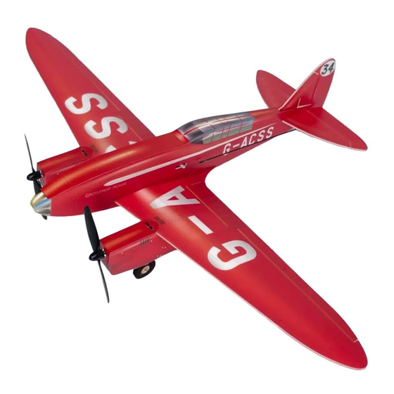
DH-88 Comet
Assembly Instructions
Important notification
1.The model is supplied with UFO and 502 glue. UFO is for bonding foam parts, and 502 for
bonding wood, carbon fiber and metal parts. 502 glue will cause serious corrosion to foam parts.
2.Please wait for the glue to dry and solidify in each installation s tep before the next installation.
3.Please avoid using flame to heat the heat shrinkable tube on the model. Electric iron shall be
used for heating.
4.Please use razor blade to remove the parts from the plate. Do not tear the parts by force.
Advertisement

Related Manuals for MinimumRC DH-88 Comet


Summary of Contents for MinimumRC DH-88 Comet
- Page 1 DH-88 Comet Assembly Instructions Important notification 1.The model is supplied with UFO and 502 glue. UFO is for bonding foam parts, and 502 for bonding wood, carbon fiber and metal parts. 502 glue will cause serious corrosion to foam parts.
- Page 2 1. Wooden frame components of the fuselage. 2. Assemble the wooden frame of the fuselage.
- Page 3 3. Connect the receiver to the servos, power it on, and bind the receiver with the tansmitter to ensure that the servo arm returns to its neutral position. Test the servos to ensure they are functioning correctly and install the servos and servo arms according to the diagram.
- Page 4 5. Use adhesive Velcro to secure the receiver. 6. Connect the receiver to the servos. Turn on the transmitter and test the correspondence between the three servos and the channels on the transmitter. After testing, use adhesive Velcro to secure the receiver and secure the cables with zip ties. 7.
- Page 5 8. Method for bending foam board pieces: Press the part that needs to be bent against the palm of your hand. 9. Press the part that needs to be bent against the edge of a table, ensuring that the palm is in close contact with the part, and slide downward.
- Page 6 11. Use glue to secure the wooden frame. 12. Press the top and bottom plates of the fuselage and bend them into the corresponding shape of the fuselage contour. 13. Use glue to secure the rear top plate of the fuselage. Note that the front end of the rear top plate should align with the cockpit position on the fuselage.
- Page 7 14. Use glue to secure the front top plate of the fuselage. 15. Use glue to secure the bottom plate of the fuselage. Note: Do not apply glue to the indicated position on the front bottom plate (yellow contour) in the diagram.
- Page 8 17. Close the fuselage. 18. Apply decals to the fuselage. 19. The front bottom plate of the fuselage can be opened forward as a battery compartment cover. When the cover is closed, it should be secured using the end of the decal.
- Page 9 20. Use a sharp tool (screwdriver) to score through the marked lines on the bottom of the horizontal stabilizer, allowing the elevator to move freely along the lines on both sides. 21. Use a sharp tool (screwdriver) to score through the marked lines on the bottom of the vertical stabilizer, allowi ng the rudder to move freely along the lines on both sides.
- Page 10 23. Insert the horizontal stabilizer into the pre -cut slot on the fuselage and secure it. Ensure that the horizontal stabilizer is parallel to the wing spar. 24. Install the vertical stabilizer. 25. The two motor compartments are designed to be mirror symmetrical. Please assemble both motor compartments simultaneously to avoid confusion.
- Page 11 26. Assembled framework of the two motor compartments. The side with the circular holes should face the fuselage. 27. Wheel axle sleeves, wheel hubs, and tires. 28. Assemble the wheel axle sleeves and wheel hubs and use glue to secure them.
- Page 12 29. Assemble the wheel hubs and tires and use glue to secure them. 30. Install the wheels on the wire landing gear. Bend the wire at the end upward using needle - nose pliers to prevent the wheels from coming off. Alternatively, insert a short piece of heat shrink tubing at the end of the wire, hea t it to shrink, and use glue for additional fixation to prevent the wheels from coming off.
- Page 13 31. Install the landing gear on both sides in a mirrored symmetrical manner. 32. Differentiate the parts of the motor compartment. The parts with circular holes should face the fuselage.
- Page 14 34. Pass the motor wires through the circular holes. 35. Press the top and bottom plates of the motor compartment and bend them into the corresponding shape of the motor compartment contour. 36. Use glue to secure the bottom plate of the motor compartment.
- Page 15 37. Use glue to secure the top plate of the motor compartment. 38. Install the completed motor compartments on both sides in a mirrored symmetrical manner. 39. Install the motor compartments on both sides.
- Page 16 40. Install the tail brace at the tail of the fuselage. 41. Use a sharp tool (screwdriver) to score along the wing's marked line, allowing the wing to fold downward along the center longitudinal line to form the airfoil. 42. Use a sharp tool (screwdriver) to score along the aileron's marked line, allowing the aileron to move up and down along the line.
- Page 17 43. Paste carbon fiber rods on the bottom of the wing along the marked line to increase strength. 44. Install the wing. 45. Install the wing root.
- Page 18 46. Apply decals to the motor compartments. 47. Install the elevator control horn. 48. Install the rudder control horn.
- Page 19 49. Cut four pieces of heat shrink tubing, each 5mm in length, for connecting the tail control rods and steel wire clips. 50. Use heat shrink tubing to connect the control rods to the steel wire clips and secure them with epoxy adhesive.
- Page 20 52. Attach the control rod clips onto the servo arms. 53. Trim the carbon fiber rod to an appropriate length. Use heat shrink tubing to connect the carbon fiber rod to the connecting hook and secure it with epoxy adhesive. 54.
- Page 21 55. Install connecting hooks on the aileron control horns. 56. Insert the wire clips into the fuselage as shown in the picture and attach them onto the aileron servo arms. 57. Use heat shrink tubing to connect the aileron wire clevises to the connecting hooks and secure them with epoxy adhesive.
-
Page 22: Maiden Flight
58. Place the battery in the fuselage. Assembly complete! Maiden flight ·The center of gravity of the aircraft is located at the front score line of the upper wing. ·The active range of ailerons, elevator and rudder is 5mm on both sides. ·choose grass land for maiden flight.
Need help?
Do you have a question about the DH-88 Comet and is the answer not in the manual?
Questions and answers