Advertisement
Quick Links
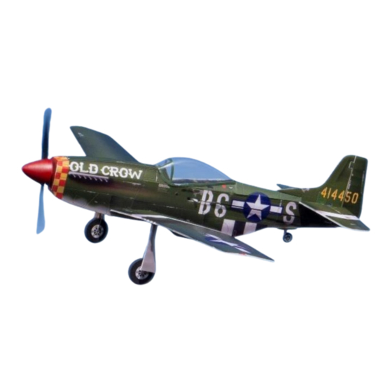
P-51 Mustang
Assembly Instructions
Important Instructions
1.The model is supplied with UFO and 502 glue. UFO is for bonding foam parts, and 502 for
bonding wood, carbon fiber and metal parts. 502 glue will cause serious corrosion to foam parts.
2.Please wait for the glue to dry and solidify in each installation step before the next installation.
3.Please avoid using flame to heat the heat shrinkable tube on the model. Electric iron shall be
used for heating.
4.Please use razor blade to remove the parts from the plate. Do not tear the parts by force.
Advertisement

Related Manuals for MinimumRC P-51 Mustang


Summary of Contents for MinimumRC P-51 Mustang
- Page 1 P-51 Mustang Assembly Instructions Important Instructions 1.The model is supplied with UFO and 502 glue. UFO is for bonding foam parts, and 502 for bonding wood, carbon fiber and metal parts. 502 glue will cause serious corrosion to foam parts.
- Page 2 1. Fuselage wooden frame parts. 2. Assemble the fuselage wooden frame. 3. Continue assembling the wooden frame and install the motor.
- Page 3 4. Overlap and install two servo wooden spacers. (Bottom view of the parts) 5. Install the servo as shown. (Top view of the parts) 6. Install the servo as shown. (Bottom view of the parts)
- Page 4 7. Connect the receiver to the servos, secure the receiver with Velcro, power it on, and bind it to the transmitter to ensure that the servo arms return to their neutral positions. Test if the servos are functioning correctly and install the servos and arms as shown in the diagram.
- Page 5 Use a sharp tool (screwdriver) to score through the marked lines on the bottom of the fuselage. 10. Magnets and its supporting structures. 11. Install the magnet.
- Page 6 12. Install the assembled magnet-supporting structure onto the wooden frame at the corresponding location. 13. Use glue to secure the wooden frame and attach the fuselage to one sides of the wooden frame, with the side marked with lines facing inward. 14.
- Page 7 15. Press the fuselage inward along the score lines and use glue to install the bulkhead. 16. Use glue to secure the cockpit foam board. 17. Use glue to secure the front fuselage top plate and nose filler plate.
- Page 8 18. Use glue to secure the fuselage bottom plate, do not apply glue to the red -lined section. 20. Combine the fuselage.
- Page 9 21. Remove the propeller and apply the fuselage stickers. 22. The front bottom plate of the fuselage can be opened forward as a battery compartment cover. 23. Install magnets at the circular hole position of the battery compartment cover.
- Page 10 24. Seal the mounting holes with sticker. 25. Install the tailwheel in the corresponding slot on the bottom of the aircraft. 26. Apply stickers to the aircraft tailwheel.
- Page 11 27. Cut off the excess parts of the canopy cover vacuum -formed part as shown in the diagram. 28. Trim to the finished size. 29. Install the canopy onto the fuselage at the corresponding location.
- Page 12 30. Apply stickers to the canopy. 31. Install the propeller and spinner, using a small amount of glue to secure the spinner. 32. Use a sharp tool (screwdriver) to score through the marked lines on the bottom of the horizontal stabilizer, allowing the elevator to move freely along the lines on both sides.
- Page 13 33. Use a sharp tool (screwdriver) to score through the marked lines on the bottom of the vertical stabilizer, allowing the rudder to move freely along the lines on both sides. 34. Install the vertical stabilizer reinforcement. 35. Attach the vertical stabilizer to the horizontal stabilizer.
- Page 14 36. Attach the horizontal stabilizer to the corresponding location on the fuselage, ensuring that the horizontal stabilizer is parallel to the wing spar. 37. Use stickers to conceal the vertical stabilizer reinforcement.
- Page 15 39. Use a sharp tool (screwdriver) to score along the wing's marked line, allowing the wing to fold downward along the center longitudinal line to form the airfoil. 40. Use a sharp tool (screwdriver) to score along the aileron's marked line, allowing the aileron to move up and down along the line.
- Page 16 42. Install the wings. 43. The landing gear on both sides is designed to be mirror symmetric. Synchronize the mirror symmetric assembly of both landing gears to avoid confusion. 44. Assemble both landing gears.
- Page 17 45. Install the landing gear at the corresponding position on the wing. 46. Install the landing gear cover plate reinforcement and bend the landing gear wire to be parallel. 47. Observe from the front; the landing gear wire should be vertical to the ground.
- Page 18 48. Install the landing gear rigid reinforcement structure at the corresponding location. 49. Axle sleeves, hubs, and tires. 50. Assemble the axle sleeve and hub, securing with glue.
- Page 19 51. Assemble the hub and tire, securing with glue. 52. Apply stickers to the hub. 53. Install the wheels and bend the landing gear wire at the tail end to prevent the wheels from falling off. Alternatively, slide heat shrink tubing over the wire end, heat - shrink it, and apply a small amount of glue to prevent the wheels from falling off.
- Page 20 54. Install the landing gear cover plate. 55. Install the aileron control horns. 56. Install the horizontal stabilizer control horns.
- Page 21 57. Install the vertical stabilizer control horns. 58. Cut four 5mm lengths of heat shrink tubing for connecting the tail control rods and wire clips. 59. Use heat shrink tubing to connect the control rods and servo wire clamp heads, then apply 502 glue for fixation.
- Page 22 60. Install connection hooks on the tail control horns. 61. Mount the control rod clamp heads on the servo arms. 62. Trim the carbon fiber rod to the appropriate length. Use heat shrink tubing to connect the carbon fiber rod to the connection hook, then apply 502 glue for fixation.
- Page 23 65. Install connection hooks on the aileron control horns.
- Page 24 66. Insert the wire clamp heads into the fuselage and install them on the aileron servo arms. 67. Use heat shrink tubing to connect the aileron wire clamp heads to the connection hooks, then apply 502 glue for fixation. 68. Place the battery in the cabin.
- Page 25 Assembly complete! Maiden flight ·The center of gravity of the aircraft is located at the front score line of the upper wing. ·The active range of ailerons, elevator and rudder is 5mm on both sides. ·choose grass land for maiden flight.
Need help?
Do you have a question about the P-51 Mustang and is the answer not in the manual?
Questions and answers