Advertisement
Quick Links
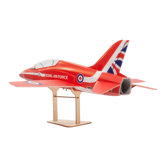
BAE Hawk- Red Arrows
Assembly Instructions
Important Instructions
1.The model is supplied with UFO and 502 glue. UFO is for bonding foam parts, and 502 for bonding
wood, carbon fiber and metal parts. 502 glue will cause serious corrosion to foam parts.
2.Please wait for the glue to dry and solidify in each installation step before the next installation.
3.Please avoid using flame to heat the heat shrinkable tube on the model. Electric iron shall be used
for heating.
4.Please use razor blade to remove the parts from the plate. Do not tear the parts by force.
Advertisement

Related Manuals for MinimumRC BAE Hawk Red Arrows


Summary of Contents for MinimumRC BAE Hawk Red Arrows
- Page 1 BAE Hawk- Red Arrows Assembly Instructions Important Instructions 1.The model is supplied with UFO and 502 glue. UFO is for bonding foam parts, and 502 for bonding wood, carbon fiber and metal parts. 502 glue will cause serious corrosion to foam parts. 2.Please wait for the glue to dry and solidify in each installation step before the next installation.
- Page 2 1. Wooden display rack. 2. Fuselage wooden frame parts and printed components. 3. Assemble the fuselage wooden frame parts and printed components.
- Page 3 5. Install the servo as shown. (Top view of the parts) 6. Install the servo as shown. (Bottom view of the parts)
- Page 4 7. Secure the receiver with Velcro. 8. Connect the receiver to the servo. Bind the receiver with the transmitter, and test whether the servo is functioning properly, ensuring that the servo's correspondence with the channels is correct. 9. The aileron servo uses a cross-shaped arm.
- Page 5 10. Remove the two adjacent arms of the cross-shaped arm. 11. Install the arms onto the servos. 12. Magnets and its supporting structure.
- Page 6 13. Install the magnetic assembly according to the diagram. 14. Mount the propeller onto the motor. Ensure that the blades are fully secured in place.
- Page 7 15. Assemble the motor with the printed duct component, adjust the motor installation depth, ensuring that the propeller blades are as close to the support structure as possible and rotate freely. Use glue to secure the motor from the rear end, as shown in the diagram.
- Page 8 18. Use a sharp tool (screwdriver) to score through the marked lines on the fuselage. 19. Caution: When performing engraving operations, make sure to press on the part closest to the engraving lines to avoid tearing the components. (As shown in the diagram)
- Page 9 21. Assemble one side of the fuselage, the wooden framework, and the duct with glue. Connect the motor to the receiver and test it to confirm that the motor rotation direction is correct. 22. The positioning tip of the duct should be fully embedded into the fuselage.
- Page 10 24. PS foam parts. 25. Secure the PS board at the top of the tail section with glue.
- Page 11 26. Use glue to secure the cockpit foam board. 28. Use glue to secure the fuselage bottom plate, do not apply glue to the red-lined section.
- Page 12 29. Use glue to affix the bottom plate of the tail section. 31. Combine the fuselage.
- Page 13 32. Vertical tail fin reinforcement piece. 33. Secure the vertical tail fin reinforcement piece with glue. (As shown in the diagram) 34. Apply the fuselage stickers.
- Page 14 35. Paste the sticker for the battery cover to the bottom of the fuselage. 36. Install a magnet at the circular hole position of the battery compartment cover. 37. Seal the mounting hole with sticker.
- Page 15 38. The battery cover is magnetically attached in the closed position. Temporarily refrain from applying the bottom tail sticker. 39. Install the vertical tail fin. 40. Use stickers to conceal the vertical tail fin reinforcement.
- Page 16 41. Use a sharp tool (screwdriver) to score through the marked lines on the bottom of the horizontal stabilizers, allowing the elevator to move freely along the lines on both sides. 42. Install the horizontal stabilizers. 43. Use a sharp tool (screwdriver) to score along the wing's marked line, allowing the wing to fold downward along the center longitudinal line to form the airfoil.
- Page 17 44. Use a sharp tool (screwdriver) to score along the aileron's marked line, allowing the aileron to move up and down along the line. 45. Install the wings. 46. Wing patches.
- Page 18 47. Align the cut and use glue to secure the wing patches in place. 48. Intake port PS foam board. 49. Bend the intake port PS foam board slightly. Method: Press the part that needs to be bent against your palm, place it on the edge of the table, and slide and squeeze it to create a curved shape.
- Page 19 50. Place the part that needs to be bent against your palm, press it against the edge of the table, and slide it to create a curved shape. 51. Install the intake port PS foam board. Apply glue on both installation surfaces to ensure strong adhesion.
- Page 20 53. Bend the intake port component slightly. Method: Press the part that needs to be bent against your palm, place it on the edge of the table, and slide and squeeze it to create a curved shape. 54. Place the part that needs to be bent against your palm, press it against the edge of the table, and slide it to create a curved shape.
- Page 21 55. Install the intake KT foam board. Apply glue on both installation surfaces to ensure strong adhesion. 56. Apply the intake sticker.
- Page 22 57. Trim the excess portions of the vacuum-formed canopy as shown in the diagram. It is advisable to make a conservative initial cut, place the canopy on the fuselage for alignment, and then proceed with precise adjustments. 58. Trim to the finished size. 59.
- Page 23 60. Apply stickers to the canopy. 61. Install the elevator control horns. 62. Install the aileron control horns.
- Page 24 63. Cut out the bottom PS board to create a hollow. 64. Retrieve two 130mm carbon rods for use as tail control rods. Cut four pieces of heat shrink tubing, each 5mm in length, to connect the tail control rods and the wire clamp heads.
- Page 25 65. Use heat shrink tubing to connect the control rods and servo wire clamp heads, then apply 502 glue for fixation. 66. Insert the tail control rods into the fuselage from the tail end, and connect them to the tail fin servo arm. 67.
- Page 26 68. Install the connecting hook on the elevator control horn. 69. Trim the carbon fiber rod to the appropriate length. Use heat shrink tubing to connect the carbon fiber rod to the connection hook, then apply 502 glue for fixation. 70.
- Page 27 71. Retrieve two 60mm carbon rods for use as aileron control rods. Cut four pieces of heat shrink tubing, each 5mm in length, to connect the aileron control rods and the wire clamp heads. 72. Use heat shrink tubing to connect the control rods and servo wire clamp heads, then apply 502 glue for fixation.
- Page 28 73. Insert the wire clamp heads into the fuselage, and install them onto the aileron servo arms. 74. Install the connecting hooks on the aileron control horns. 75. Use heat shrink tubing to connect the aileron control rods to the connection hooks, then apply 502 glue for fixation.
- Page 29 76. Paste reinforcing carbon rods and control horns protectors at the bottom of the wing. 77. Place the battery at the front end of the fuselage compartment. Assembly complete!
-
Page 30: Maiden Flight
Maiden flight ·The center of gravity of the aircraft is located 5mm in front of the wing scored line. ·The active range of ailerons, elevator and rudder is 4mm on both sides. ·Choose grass land for maiden flight.
Need help?
Do you have a question about the BAE Hawk Red Arrows and is the answer not in the manual?
Questions and answers