Advertisement
Quick Links
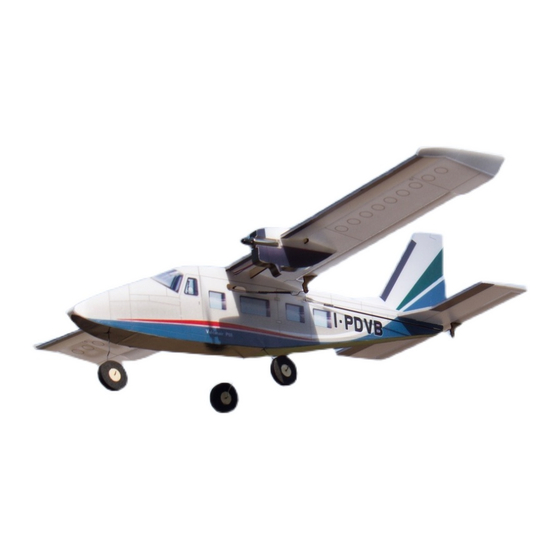
Vulcanair P-68
Assembly Instructions
Important notification
1.The model is supplied with UFO and 502 glue. UFO is for bonding foam parts, and 502 for
bonding wood, carbon fiber and metal parts. 502 glue will cause serious corrosion to foam parts.
2.Please wait for the glue to dry and solidify in each installation step before the next installation.
3.Please avoid using flame to heat the heat shrinkable tube on the model. Electric iron shall be
used for heating.
4.Please use razor blade to remove the parts from the plate. Do not tear the parts by force.
Advertisement

Related Manuals for MinimumRC Vulcanair P-68


Summary of Contents for MinimumRC Vulcanair P-68
- Page 1 Vulcanair P-68 Assembly Instructions Important notification 1.The model is supplied with UFO and 502 glue. UFO is for bonding foam parts, and 502 for bonding wood, carbon fiber and metal parts. 502 glue will cause serious corrosion to foam parts.
- Page 2 1. Fuselage internals. 2. Bond the inner structure of the fuselage with 502 glue. 3. Fix the main gear steel wire with m1x3 screws.
- Page 3 4. Fix the main gear steel wire with m1x3 screws. 5. Fix the nose gear steel wire with glue.
- Page 4 7. Fuselage parts...
- Page 5 9. Connect the servos to a powered receiver. Bind the receiver with your transmitter to make the servos arms return to their neutral point. Test whether the servos are working normally, and install the servo arms according to the position shown in the picture. Note: Please make sure that the servos have been tested and installed in strict accordance with the following picture.
- Page 6 11. Combine the fuselage and paste fuselage side stickers . 12. Insert the copper axle core into the center of the wood wheel core. 13. Glue the tires.
- Page 7 14. bend the outer end of the steel wire with pointed nose pliers. 15. Use the end of a carbon fiber rod to score through the half -cut line of the rudder surface. 16. Use the end of a carbon fiber rod to score through the half -cut line of the elevator surface.
- Page 8 17. Install the tail. 18. Score through the half-cut line of the wing & aileron surface. 19. Combine the engine compartment parts.
- Page 9 20. Engine compartments. 21. Install the engine compartment symmetrically and fix the motor with glue. 22. Attach the wing to the fuselage.
- Page 10 23. Motor wires pass through the hole on side of the fuselage. 24. Install the wing tips. 25. Install the aileron control horns.
- Page 11 26. Install the elevator control horn. 27. Install the rudder control horn. 28. Use heat shrinkable tube to connect the push rod and wire clip, then use glue to fix them.
- Page 12 30. Attach the pushrods to servo arms. 31. Attach the steel wire hooks to the control horns, cut the carbon fiber rod to proper length and connect the rod & wire hooks with heat -shrinkable tubes.
- Page 13 33. Aileron pushrods. 34. Install the aileron pushrods.
- Page 14 35. Cabin hatch magnet & magnet base. 37. Receiver placed inside the cabin.
-
Page 15: Maiden Flight
38. Battery placed inside the cabin and fixed with Velcro. Assembly complete! Maiden flight ·The center of gravity of the aircraft is located at the front score line of the wing. ·The active range of elevator, rudder and aileron is 5mm on both sides. ·choose grass land for maiden flight.
Need help?
Do you have a question about the Vulcanair P-68 and is the answer not in the manual?
Questions and answers