Advertisement
Quick Links
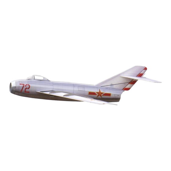
Mig-15
Assembly Instructions
Important Instructions
1.The model is supplied with UFO and 502 glue. UFO is for bonding foam parts, and 502 for bonding
wood, carbon fiber and metal parts. 502 glue will cause serious corrosion to foam parts.
2.Please wait for the glue to dry and solidify in each installation step before the next installation.
3.Please avoid using flame to heat the heat shrinkable tube on the model. Electric iron shall be used
for heating.
4.Please use razor blade to remove the parts from the plate. Do not tear the parts by force.
Advertisement

Related Manuals for MinimumRC Mig-15


Summary of Contents for MinimumRC Mig-15
- Page 1 Mig-15 Assembly Instructions Important Instructions 1.The model is supplied with UFO and 502 glue. UFO is for bonding foam parts, and 502 for bonding wood, carbon fiber and metal parts. 502 glue will cause serious corrosion to foam parts. 2.Please wait for the glue to dry and solidify in each installation step before the next installation.
- Page 2 1. Wooden display rack. 2. Fuselage wooden frame parts and nose support components. 3. Assemble the fuselage wooden frame parts and nose support components.
- Page 3 4. Install the servos as shown. (Top view of the parts.) 5. Install the servos as shown. (Bottom view of the parts.) 6. Secure the receiver with Velcro. Connect the receiver to the servos and bind the receiver with the transmitter. Test whether the servos are functioning properly, ensuring that the servos' correspondence with the channels are correct.
- Page 4 7. Using zip ties to secure cables. 8. The aileron servo uses a cross-shaped arm. 9. Remove the two adjacent arms of the cross-shaped arm.
- Page 5 10. Install the arms onto the servos.. 11. Rear components of the frame. 12. Installation of magnet base and magnets.
- Page 6 13. Installation of rear printed parts. 14. Installation of wing spar. 15. Duct components.
- Page 7 16. Assembly duct components. 17. Mount the propeller onto the motor and ensure it is fully secured in place. 18. Assemble the motor with the duct component, adjust the motor installation depth, ensuring that the propeller blades are as close to the support structure as possible and rotate freely (Failure to position the blades close to the support will significantly decrease thrust).
- Page 8 19. Connect the motor to the receiver and test it to confirm that the motor rotation direction is correct. 21. Use a sharp tool (screwdriver) to score through the marked lines on the fuselage.
- Page 9 22. Caution: when performing scoring operations, make sure to press on the part closest to the lines to avoid tearing the components. (As shown in the diagram.) 23. Assemble one side of the fuselage, the wooden framework, and the duct with glue.
- Page 10 25. PS foam parts. 26. Secure the top PS foam board with glue. 27. Secure the bottom PS foam board with glue.
- Page 11 28. Secure the battery cover PS foam board with glue. Do not apply glue to the red-lined section. 30. Combine the fuselage.
- Page 12 31. Apply the top stickers to the fuselage. 32. Apply the bottom sticker to the tail end of the fuselage. 33. Apply stickers to the bottom of the aircraft nose.
- Page 13 34. Install a magnet at the circular hole position of the battery compartment cover. 35. Seal the mounting hole with sticker.
- Page 14 37. Trim the excess portions of the vacuum-formed canopy as shown in the diagram. It is advisable to make a conservative initial cut, place the canopy on the fuselage for alignment, and then proceed with precise adjustments. 38. Trim to the finished size. 39.
- Page 15 40. Apply stickers to the canopy. 41. Install the vertical tail fin. 42. Use stickers to conceal the vertical tail fin reinforcement.
- Page 16 43. Use a sharp tool (screwdriver) to score through the marked lines on the bottom of the horizontal stabilizers, allowing the elevator to move freely along the lines on both sides. 44. Install the horizontal stabilizers. 45. Install horizontal tail support rods.
- Page 17 46. Install the horizontal tail fin end patch. 47. Use a sharp tool (screwdriver) to score along the wing's marked line, allowing the wing to fold downward along the center longitudinal line to form the airfoil. 48. Use a sharp tool (screwdriver) to score along the aileron's marked line, allowing the aileron to move up and down along the line.
- Page 18 49. Install the wings. 50. Install winglets, paying attention to the different widths of the inner and outer winglet installation tenons. 51. Stick carbon fiber rods at the bottom of the wings to increase strength.
- Page 19 52. Install the aileron control horns. 53. Install the elevator control horns. 54. Retrieve two 230mm carbon rods for use as elevator control rods. Cut four pieces of heat shrink tubing, each 5mm in length, to connect the elevator control rods and the wire clamp heads.
- Page 20 56. Use heat shrink tubing to connect the control rods and servo wire clamp heads, then apply 502 glue for fixation. 57. Install the connection hooks on the elevator control horns.
- Page 21 58. Insert the carbon rod with steel wire clamp into the fuselage, and mount it on the horizontal tail servo arm. 60. Use heat shrink tubing to connect the control rods to the connection hooks, then apply 502 glue for fixation.
- Page 22 61. Retrieve two 75mm carbon rods for use as aileron control rods. Cut four pieces of heat shrink tubing, each 5mm in length, to connect the aileron control rods and the wire clamp heads. 62. Use heat shrink tubing to connect the control rods and servo wire clamp heads, then apply 502 glue for fixation.
- Page 23 64. Insert the wire clamp heads into the fuselage, and attach them onto the aileron servo arms. 65. Use heat shrink tubing to connect the control rods to the connection hooks, then apply 502 glue for fixation.
- Page 24 66. Place the battery at the front of the fuselage. Use Velcro to secure the counterweight iron plates on the inner wall of the nose for center of gravity adjustment. Assembly complete!
-
Page 25: Maiden Flight
Maiden flight ·When using the original electronic equipment of this model, one counterweight iron plate needs to be installed on the nose. When using other electronic devices, please adjust the center of gravity to 5-10mm behind the wooden wing spar. ·The elevator and aileron control have a range of 3-5mm on each side.
Need help?
Do you have a question about the Mig-15 and is the answer not in the manual?
Questions and answers
What type of glue is required
The MinimumRC Mig-15 requires two types of glue: UFO glue for bonding foam parts, and 502 glue for bonding wood, carbon fiber, and metal parts.
This answer is automatically generated