Advertisement
Quick Links
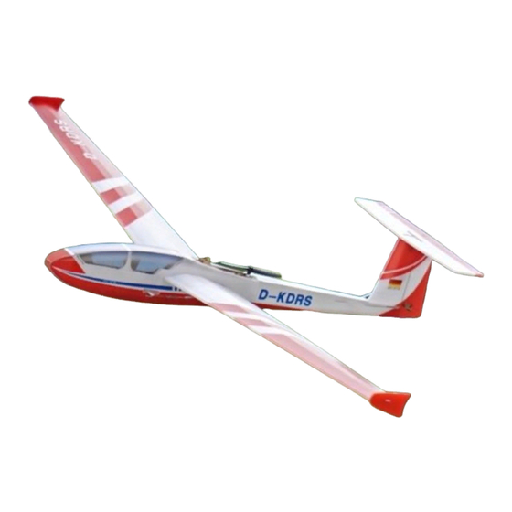
ASG-32 Glider
Assembly Instructions
Important notification
1.The model is supplied with UFO and 502 glue. UFO is for bonding foam parts, and 502 for
bonding wood, carbon fiber and metal parts. 502 glue will cause serious corrosion to foam parts.
2.Please wait for the glue to dry and solidify in each installation step before the next ins tallation.
3.Please avoid using flame to heat the heat shrinkable tube on the model. Electric iron shall be
used for heating.
4.Please use razor blade to remove the parts from the plate. Do not tear the parts by force.
1. Fuselage internals
Advertisement

Related Manuals for MinimumRC ASG-32


Summary of Contents for MinimumRC ASG-32
- Page 1 ASG-32 Glider Assembly Instructions Important notification 1.The model is supplied with UFO and 502 glue. UFO is for bonding foam parts, and 502 for bonding wood, carbon fiber and metal parts. 502 glue will cause serious corrosion to foam parts.
- Page 2 2. Bond the inner structure of the fuselage with 502 glue. Please pay attention to the opening direction of the servo base.
- Page 3 3. Combined motor base, use 502 glue to fix the motor. 4. Use m1.2x6mm screw to fix the turnover motor base. Adjust the distance between the fixed pieces on both sides of the motor base till the motor base can be turned over freely. If necessary, sand the motor base to reduce its thickness to make the turning movement smooth.
- Page 4 5. Screw in another m1.2x6 screw from the right side to form the motor line limit to prevent the motor line from interfering with the motor base movement or propeller running. 6.Connect the servos to a powered receiver. Bind the receiver with your transmitter to make the servos return to their neutral point.
- Page 5 7. Install the receiver. No glue is required here. 8.Connect the cable of servos and motor, and connect the receiver to power for test. Ensure that the servos and motor work normally and the motor rotation direction is correct. Secure the cable with ties. Note: please make sure the motor rotation direction is correct.
- Page 6 9. Combine the fuselage inner structure with the right panel of the fuselage. Note: the bottom of inner structure (red circles) should be 2mm away from the edge . 10. Use the end of a carbon fiber rod to score through the half -cut line of the tail surface.
- Page 7 11. As shown in the figure, glue the fuselage side strips (and vertical tail) to the inside of the right fuselage side panel in the order of A-B-C-D-E-F. ·The fuselage side strips are made of flexible material, which can be bent before bonding. ·In strict accordance with the A-B-C-D-E-F sequence installation, can ensure the accurate position of the fuselage side strips.
- Page 8 13. As shown in the figure, paste a conduit seat inside the right side of the fuselage. The distance between the seat and the conduit hole on the side plate is about 30mm. 14. As shown in the figure, paste a duct seat on the right side of the vertical tail. This guide socket is used to fix the end of elevator drive pipe.
- Page 9 15. Glue the conduit to the conduit base inside the fuselage, and the two ends of the conduit pass through the two conduit holes on the right side of the fuselage. Left end of the guide pipe extends out of the fuselage by 5mm. 16.
- Page 10 17. Install the duct on the left side of the fuselage as shown. Take one 170mm conduit and one duct base. Paste the duct base inside the left side of the fuselage, 30mm away from the duct hole. 18. Glue the conduit to the conduit base on the left side of the fuselage, both of the ends of the conduit pass through the conduit hole.
- Page 11 19. Picture: the two ends of the left guide pipe pass through the holes on the fuselage, and the length of the two ends is 5mm. 20. Close the fuselage on both sides and glue. Pay attention to keep the fuselage edge aligned with the fuselage side panel edge.
- Page 12 21. Paste the sticker on the side of the fuselage. The sticker acts as a hinge for the hatch opening and closing, so the sticker at the nose (red circle) needs to be reinforced with glue to increase reliability. 22. Install the horizontal tail with the scribe face down.
- Page 13 23. Install rudder and elevator control horn. The elevator control horn is special in shape and it should be pointed to the tail of the aircraft during installation. 24. Cut 4 pieces of 5mm long transparent heat shrinkable tube to connect the steel wire and the pushrod clips.
- Page 14 25. Thread the steel wire into the conduit on the fuselage. The steel wire is used for elevator drive, and the shorter one is used for rudder drive. 26. Install the pushrod clip on the rudder control horn and connect it with the wire by using a heat shrinkable tube.
- Page 15 27. Connect elevator control horn, pushrod clip and steel wire. 28. Connect the pushrod clip, steel wire and servo arm. 29. Cut off the connection points on the side of the hatch cover so that it can be lifted forward.
- Page 16 30. Take two magnets and two magnet mounting seats. 31. Fix the magnet to the wooden mounting base with 502 glue. 32. Install the fuselage magnet seat.
- Page 17 33. Install the hatch magnet seat. 34. Use the end of a carbon fiber rod to score through the half -cut line of the wing surface. 35. Install wings and wing tips.
- Page 18 36. Attach a 250mm carbon fiber rod on each bottom side of wings. 37. The battery is placed in the cabin. Assembly complete!
- Page 19 Before the first flight test, the elev ator can be adjusted up slightly. When the aircraft is out of the stall, the bow torque will disappear. ·It is not recommended for beginners to operate this model. Enjoy your flight! Explore the ultimate possibility of RC aviation www.MinimumRC.com...
Need help?
Do you have a question about the ASG-32 and is the answer not in the manual?
Questions and answers