Advertisement
Quick Links
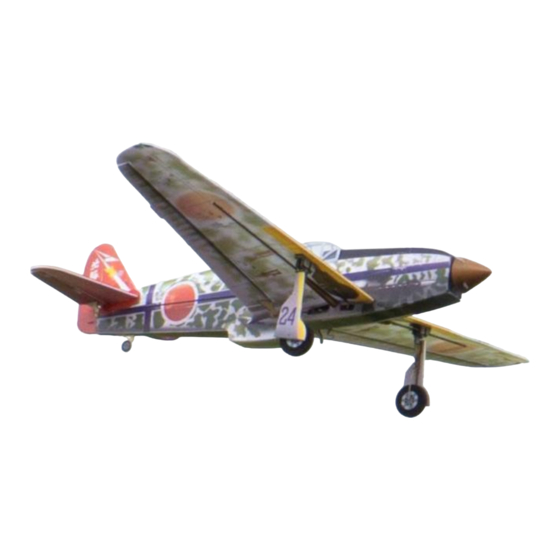
KI-61 Tony
Assembly Instructions
Important Instructions
1.The model is supplied with UFO and 502 glue. UFO is for bonding foam parts, and 502 for bonding
wood, carbon fiber and metal parts. 502 glue will cause serious corrosion to foam parts.
2.Please wait for the glue to dry and solidify in each installation step before the next installation.
3.Please avoid using flame to heat the heat shrinkable tube on the model. Electric iron shall be used
for heating.
4.Please use razor blade to remove the parts from the plate. Do not tear the parts by force.
Advertisement

Related Manuals for MinimumRC KI-61 Tony


Summary of Contents for MinimumRC KI-61 Tony
- Page 1 KI-61 Tony Assembly Instructions Important Instructions 1.The model is supplied with UFO and 502 glue. UFO is for bonding foam parts, and 502 for bonding wood, carbon fiber and metal parts. 502 glue will cause serious corrosion to foam parts.
- Page 2 1. Fuselage wooden frame parts. 2. Assemble the fuselage wooden frame. 3. Continue assembling the wooden frame and install the motor.
- Page 3 4. Install the servo as shown. (Top view of the parts) 6. Install the servo as shown. (Bottom view of the parts)
- Page 4 7. Magnets and its supporting structures. 8. Install the magnet. 9. Install the assembled magnet-supporting structure onto the wooden frame at the corresponding location.
- Page 5 10. The landing gear servo uses a cross-shaped arm. 11. Remove the two opposite arms of the cross-shaped arm (as shown in the diagram). 12. Install the arm onto the landing gear servo.
- Page 6 13. Connect the receiver to the servos, secure the receiver with Velcro, power it on, and bind it to the transmitter to ensure that the servo arms return to their neutral positions. Test if the servos are functioning correctly and install the servos and arms as shown in the diagram.
- Page 7 15. Use a sharp tool (screwdriver) to score through the marked lines on the bottom of the fuselage. 16. Use glue to secure the wooden frame and attach the fuselage to one sides of the wooden frame, with the side marked with lines facing inward.
- Page 8 17. PS foam parts. 18. Press the fuselage inward along the score lines and use glue to install the bulkhead. 19. Use glue to secure the foam board at the bottom of the tail of the aircraft.
- Page 9 20. Use glue to secure the cockpit foam board. 21. Use glue to secure the nose filler plate. 22. Use glue to secure the front fuselage top plate.
- Page 10 23. Use glue to secure the fuselage bottom plate, do not apply glue to the red-lined section. 24. Use glue to secure the bottom and top plates. 25. Install the air vent top plate.
- Page 11 26. Combine the fuselage. 27. Remove the propeller and apply the fuselage stickers. 28. Install the seat compartment wooden pieces with glue.
- Page 12 29. The front bottom plate of the fuselage can be opened forward as a battery compartment cover. 30. Install magnets at the circular hole position of the battery compartment cover. 31. Seal the mounting holes with sticker.
- Page 13 32. Install the tailwheel in the corresponding slot on the bottom of the aircraft. 33. Apply stickers to the aircraft tailwheel.
- Page 14 34. Trim the excess portions of the vacuum-formed canopy as shown in the diagram. It is advisable to make a conservative initial cut, place the canopy on the fuselage for alignment, and then proceed with precise adjustments. 35. Trim to the finished size.
- Page 15 36. Install the canopy onto the fuselage at the corresponding location. 37. Apply stickers to the canopy. 38. Install the propeller and spinner, using a small amount of glue to secure the spinner.
- Page 16 39. Use a sharp tool (screwdriver) to score through the marked lines on the bottom of the horizontal stabilizer, allowing the elevator to move freely along the lines on both sides. 40. Use a sharp tool (screwdriver) to score through the marked lines on the bottom of the vertical stabilizer, allowing the rudder to move freely along the lines on both sides.
- Page 17 41. Install the vertical stabilizer reinforcement. 42. Attach the vertical stabilizer to the horizontal stabilizer. 43. Attach the horizontal stabilizer to the corresponding location on the fuselage, ensuring that the horizontal stabilizer is parallel to the wing spar.
- Page 18 44. Use stickers to conceal the vertical stabilizer reinforcement. 45. Use a sharp tool (screwdriver) to score along the wing's marked line, allowing the wing to fold downward along the center longitudinal line to form the airfoil.
- Page 19 46. Use a sharp tool (screwdriver) to score along the aileron's marked line, allowing the aileron to move up and down along the line. 47. Paste carbon fiber rods at the bottom of the wing to increase wing strength. 48. Install the wings.
- Page 20 49. Assemble the components required for retracting and extending the landing gear. 50. Install the landing gear wires into their respective holes and secure them with adhesive (as shown in the diagram).
- Page 21 51. Assemble the retracting and extending mechanism using screws and nuts (as shown in the diagram). 52. Adjust the tightness of the screws and nuts to allow for smooth movement. 53. Use adhesive to secure the nuts in place to prevent them from coming loose.
- Page 22 54. The landing gear on both sides is designed with mirror symmetry. Please assemble both sides of the landing gear in a mirrored symmetrical manner to avoid any confusion. 55. Axle sleeves, hubs, and tires. 56. Assemble the axle sleeve and hub, securing with glue.
- Page 23 57. Assemble the hub and tire, securing with glue. 58. Apply stickers to the hub.
- Page 24 59. Install the wheels and bend the landing gear wire ends upward to prevent the wheels from coming off. Alternatively, cut a small piece of heat shrink tubing, slide it onto the end of the wire, shrink it, and apply a small amount of adhesive to prevent the wheels from coming off.
- Page 25 62. Check the operation of the landing gear servo while it is powered on to ensure it functions correctly (as shown in the diagram).
- Page 26 64. Cut the corresponding area on the airframe to the landing gear servo to allow the rod to pass through (as shown in the diagram).
- Page 27 67. Cut two pieces of 15mm carbon rod. 68. Use heat shrink tubing to connect the rod and the servo wire end, and apply a small amount of 502 adhesive to secure it. 69. Install the rod end clamp onto the servo arm.
- Page 28 70. Install the landing gear drive rod into the groove. 71. Use heat shrink tubing to connect the rod and the drive rod, and apply a small amount of 502 adhesive to secure it.
- Page 29 72. Install the other rod on the opposite side in the same manner, making sure the opening of the rod end clamp faces downward. 73. Adjust the length of both rods to ensure that the landing gear retracts and extends evenly into the correct position.
- Page 30 74. Bend the landing gear wires slightly towards the front of the aircraft. 75. Adjust the landing gear wires so that they are vertical to the ground when in the open position. 76. Install the aileron control horns.
- Page 31 77. Install the horizontal stabilizer control horns. 78. Install the vertical stabilizer control horns. 79. Install the landing gear cover reinforcement.
- Page 32 80. Install the landing gear cover plate. 81. Cut four 5mm lengths of heat shrink tubing for connecting the tail control rods and wire.
- Page 33 82. Use heat shrink tubing to connect the control rods and servo wire clamp heads, then apply 502 glue for fixation. 83. Install connection hooks on the tail control horns. 84. Mount the control rod clamp heads on the servo arms.
- Page 34 85. Trim the carbon fiber rod to the appropriate length. Use heat shrink tubing to connect the carbon fiber rod to the connection hook, then apply 502 glue for fixation. 87. Install connection hooks on the aileron control horns.
- Page 35 88. Insert the wire clamp heads into the fuselage and install them on the aileron servo arms. 89. Use heat shrink tubing to connect the aileron wire clamp heads to the connection hooks, then apply 502 glue for fixation.
- Page 36 91. Place the battery in the cabin. Assembly complete!
-
Page 37: Maiden Flight
Maiden flight ·The center of gravity of the aircraft is located at the front score line of the upper wing. ·The active range of ailerons, elevator and rudder is 5mm on both sides. ·choose grass land for maiden flight. ·Under no circumstances should the landing gear in motion be obstructed, as it may result in damage to the servo gears.
Need help?
Do you have a question about the KI-61 Tony and is the answer not in the manual?
Questions and answers