Table of Contents

Related Manuals for Mount-It! MI-384L


Summary of Contents for Mount-It! MI-384L
- Page 1 Height Adjustable Fireplace TV Mount DQ Atlas TV wall mount DQATL1 MI-384L INSTALLATION INSTRUCTIONS 100 x 100 800 x 500 65”-85” 61-110 lbs 28-50 kg VESA COMPLIANT For installation assistance or questions, please contact us at support@mount-it.com or (855) 925 5668.
- Page 2 The maximum temperature at the front of the fireplace mantle should never be more than 100°F (37.8°C). The fireplace mantle should not extend more than 12”(304mm) from the mounting surface. This mount can support displays weighing between 61~110lbs(28~50kg). The mounting surface should be a wood stud frame wall with studs spaced no more than 24”(609mm) apart ;...
-
Page 3: Package Contents
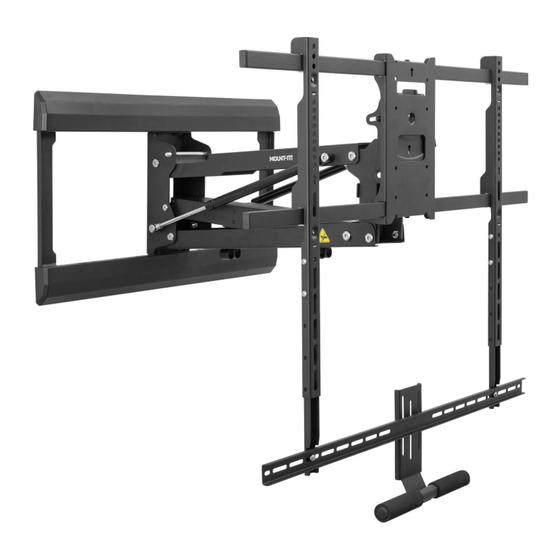
INTRODUCTION Mount your television conveniently above your fireplace using this Above Fireplace Mount. It is capable of supporting televisions with VESA patterns from 100x100 and 800x500 and weighing between 61~110 lbs (28~50kg). The mount allows you to keep the TV safely up and out of the way when not in use, then you can pull it down to eye level for comfortable viewing. -
Page 4: Required Tools
A: M4 x 16 mm B: M5 x 16 mm C: M6 x 16 mm D: M8 x25 mm E: φ16xφ6.2x1.5mm F: M5 x 8 mm G: M8 x 45 mm H: M8 x 65mm C2: 5 mm I: Concrete Anchor C1: M5 / M6 wrench C4: M6... -
Page 5: Installation Considerations
INSTALLATION CONSIDERATIONS WARNING: Please read and follow these installation considerations before beginning the installation to ensure the wall mount is compatible with your mounting location and display. The temperature at the front of the fireplace mantle must never exceed 100°F (38°C). 100°F Max STUDS If mounting to studs, the studs must be spaced no more than 24”... - Page 6 4. This fireplace TV mount is designed for larger and heavier TVs. If your TV weighs less than 61 lbs, the arm may not fully lower under the weight of the TV. Wall Space Height TV Height Mantel Clearance mantel depth 5.
-
Page 7: Installation
STUDS Installation Locate the Studs Use a stud finder to locate the studs in your wall, then mark the edges of each stud with a penci Wood Stud Installation Option Determine the placement of the template by referencing the guide on page 6, step 5. Use a bubble level to ensure straightness, then tape or hold the Template (#II) in the final mounting location and drill 4 pilot holes in the locations that line up with the center of the studs. - Page 8 Concrete/Brick Installation Option Determine the placement of the template by referencing the guide on page 6, step 5. Use a bubble level to ensure straightness, then ape or hold the Template (#II) in the final mounting location and drill 6 pilot holes, all 4 corners and 2 in the middle. Drill the pilot holes using a 3/8in drill bit to a depth of 2.7”.
- Page 9 Optional: Adjust the Horizontal Position of Connect the Spring Arm (#CC) to the Wall the Spring Arm Plate (#AA) using the Bolts (#C3)as shown here. Position the Spring Arm left or right on the Wall Plate as needed by attaching the spring arm in the required location.
- Page 10 Wood Stud Mounting Install the assembled arm to the wall using the Lag Screws (#H) and Washers (#H) as shown. Concrete/Brick Mounting Insert the Concrete Anchors (#I) into the drilled holes, then install the assembled arm to the wall using the Lag Screws (#H) and Washers (#H) as shown.
- Page 11 Lower the Arm Lock the Arm Pull the spring arm down until it is perpendicular Insert the Arm Lock Pin (#K) through the holes to the wall. shown here to lock the arm in the lowered position for easier access to hang the TV. Lock the arm Attach the VESA Arms to the TV (A/B/C)+E/D/G...
- Page 12 Attach the Crossbar (With Soundbar) Attach the Soundbar To connect a soundbar to the mount, attach the crossbar Attach the Soundbar to the bolts protruding from the back so that it is below the bottom of the screen. Secure it to of the crossbar using the Washers (#C1) and the Nuts (#C5).
- Page 13 Remove the Crossbar Latch Release 90° Keep the mount arm in this 90° angle when adjusting the spring tension (detailed below.) Adjusting the Spring Arm Tension “ + ” : Increase Tension “ - ” : Reduce Tension Adjust the tension of the spring arm until it stops freely at all Attention: lowered positions.
- Page 14 Reducing the Tension If the arm raises on its own then turn the adjustment bolt toward the “ - ” symbol to decrease tension until the arm stops at the desired position. Increasing the Tension If the arm lowers on its own then turn the adjustment bolt toward the “ + ” symbol to increase tension until the arm stops at the desired position.
-
Page 15: Level Adjustment
Level Adjustment Level adjustment±5° The Level of the screen can be adjusted ±5° by loosening the nuts on the lower back of the VESA plate shown in the magnification bubble here, then adjust to the desired level and tighten the nuts back down. Tilt and Swivel Adjustments Tilt adjustment -5 ~ +10°... -
Page 16: Cable Management
Cable Management Cables can be run through the cable management clips on the underside of the mount arm to prevent the cables from hanging freely. cable Note: Leave enough slack in the cables to accommodate or the range of motion of the mount. Install the Cover Plates Pull in the cover plates Install the decorative Cover Plates (#AA-1) onto the top and bottom of the Wall Plate.
Need help?
Do you have a question about the MI-384L and is the answer not in the manual?
Questions and answers