
Subscribe to Our Youtube Channel
Related Manuals for Mount-It! MI-373


Summary of Contents for Mount-It! MI-373
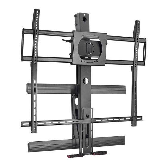
- Page 1 INSTALLATION GUIDE Mantel Arm Mount MI - 373 Support 55" to 100" Screens Load Capacity: 40~154 lbs (18~70 kg) VESA 800x600 compatible Address: 12113 Kirkham Road, Poway CA 92064...
-
Page 2: Table Of Contents
WARNING • Be sure to read this entire manual thoroughly and you fully understand all the instructions and warning before attempting to begin your installation. • Sufficient expertise is required for installing of this product. Be sure to subcontract the installation to a qualified pe- rson. -
Page 3: Parts List
Before you b egin, make sure all parts shown are included with your product. Parts may appear slightly different than illustrated. Parts List Description 15x15x40 philips pan head screw M6x12 philips pan head screw M6x25 philips pan head screw M8x12 philips pan head screw M8x25 washer(1) -
Page 4: Critical Requirements Of The Installation
CRITICAL requirements of the installation WARNING • Make sure that the supporting surface will safely support the combined load of the equipment and all attached hardware and components, Bracket installation need two people together to complete. Temperature at the front edge of mantle should If the main wall is wooden,There must be at least 2 studs never exceed 110°... -
Page 5: Installation Of The Bracket
Installation of the bracket Measure the centerline of the mantle. Mark with tape on Locate at least two studs with a stud finder. Locate the the wall. center of these studs by using a sharp awl or finish nail poked through the drywall to locate each edge. Lag bolts must be installed into the CENTER of the studs. - Page 6 Installation of the bracket Take out CC L/A from the packaging , please let the Take out K/EE/FF/N(spanner M10) from the packaging , pre-set wire go through the hole as illustrated in the picture. installation as illustrated in the picture. keep the up direction uniform (magentic spirit level) (spanner M10)
-
Page 7: Installation Of Screen & Adjustment Of The Spring Pressure
Installation of Screen & adjustment of the spring pressure Select the parts from the packaging,and according to your Take out H/I/AA/DD from the packaging,according to the TV situation to choose B+F;or C+F+G;or D;or E+G,lock with size of the TV,adjust to the approriate location,as shown cross screwdriver. -
Page 8: Product Dimensions
8 of 8...
Need help?
Do you have a question about the MI-373 and is the answer not in the manual?
Questions and answers