Advertisement
Quick Links
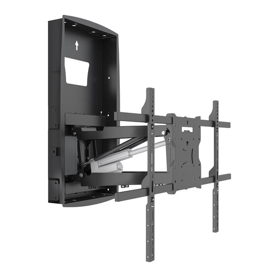
Recessed Motorized
Fireplace TV Mount
MI-302
INSTALLATION INSTRUCTIONS
110 lbs
(50 kg)
For installation assistance or questions, please contact us
at support@mount-it.com or (855) 925 5668.
42"-80"
DQ Atlas TV wall mount
DQATL1
Please scan this QR code
to visit the product page.
100 x 100
-
600 x 500
VESA
COMPLIANT
Advertisement

Related Manuals for Mount-It! MI-302


Summary of Contents for Mount-It! MI-302
- Page 1 Recessed Motorized DQ Atlas TV wall mount Fireplace TV Mount DQATL1 Please scan this QR code to visit the product page. MI-302 INSTALLATION INSTRUCTIONS 100 x 100 600 x 500 42”-80” 110 lbs (50 kg) VESA COMPLIANT For installation assistance or questions, please contact us...
- Page 2 Mount and Accessories A1: Recessed Box A2: Motorized Arm A3: VESA brackets A4: Universal Adapter plate A5:Security Clips A6:Remote Control A7:Linear actuator A8:Power Cable A9: Template TV Mounting Hardware Security Bolt M5x8 -4pcs Wall Mounting Hardware ST8x50 -10pcs -7pcs Wrench -1pcs (L=200mm) Cable Ties C2: 5mm Spacer...
- Page 3 Select TV Bolts Select TV Spacers 1.1 A–G Select Bolts 1.2 Select Spacers The back of your TV has 4 bolts holes in Plastic spacers are also provided in 2 a square or rectangular pattern. This is thicknesses to allow the mount to work where the mount will attach to your TV.
-
Page 4: Installation
Installation STUDS Mandatory Installation Requirements (Locate the Studs) Use a stud finder to locate the studs in your wall, then mark the edges of each stud with a pencil. Note: The studs will need to be the commonly used spacing of 16” from center to center (14.5” from inner edge to inner edge.) If they are farther or closer apart, this mount cannot to be installed without modifying the stud spacing or adding additional supports. - Page 5 Insert the Recessed Box Flange The box comes with tabs to firmly hold the box between the studs and may require force to insert the box fully into the wall until the flanged edges rest on the wall surface. It may be required to insert the left side of the box first until the tabs are in place. Secure the Recessed Box Lag Screw 8x50mm...
- Page 6 Insert the Motorized Arm Insert the Motorized Arm into the Recessed Box and hook the tabs in place as shown in the magnification bubble. Extend the Arm Supports Extend the arm supports on the left-hand side of the Motorized Arm. Loosen or remove the screws on that side as shown in the magnification bubble, slide the arms until they are secure against the studs through the left-hand side of the Recessed Box, and reinstall or retighten the screws to secure it in place.
- Page 7 Install the Lag Screws Tip: Press the mounting arms to the rear of the holes so that they are installed as far back on the stud as possible. This will allow the TV to reach the smallest profile distance between the TV and wall. Install the 8 remaining Lag Screws in the locations shown so that they pass through the holes on both the Motorized Arm and Recessed Box.
-
Page 8: Connect The Power
Connect the Power Connect the cable from the motorized arm to the control unit, then connect the plug to a wall outlet. Note: Power/cable ports are provided in the top, bottom and back of the recessed box for alternate power and AV options/connections. Knock out the pre-cut ports as needed to run your cables. Lower the Arm Press the down arrow on the remote control to lower the motorized arm to its lowest position. -
Page 9: Install The Control Unit
Install the Control Unit Attach the Control Unit to the inside of the Recessed Box, next to the Motorized Arm in the location shown. Secure it in place using Screws. Install the VESA Plate Locate the arrow on the VESA Plate to ensure the correct side is facing up, then hang the VESA Plate on the end of the Motorized Arm. - Page 10 Secure the VESA Plate Install Washers (#C1) and Nuts (#C3) onto the bolts protruding through the back of the plate. These nuts will also be used in the final adjustments to level the screen if needed. a: Attaching the TV to the VESA Arms For TVs with VESA Patterns 300x200-600x500.
- Page 11 b:Attaching the TV to the VESA Plate A+E or B+E or C+E or D or G For TVs with a VESA pattern of 200x200 or less remove the horizontal crossbars from the VESA Plate. Select the appropriate size mounting bolt (Select one size #A, #B, #C, #D or #G) and washer (#E) for your display’s mounting holes and verify the length of the VESA bolt is not too long.
- Page 12 Securing The TV On The Mount Center the TV on the mount arm so that the weight of the TV is balanced, then attach the 4 Security Clips in the locations shown and secure in place using Security Bolt (#F). Leveling Adjustment -5°...
- Page 13 Tilt Adjustment -5° - +10° Down The mount can tilt down up to 10 degrees and up 5 degrees. To adjust the tilt angle of the TV, loosen the tilt adjustment lever shown here then adjust the tilt to the desired angle and tighten the tilt adjustment lever back down.
-
Page 14: Cable Management
Cable Management The hole can be knocked off Cable ties Cable management Use the integrated cable management clips on the arms to route cables to the back or side of the TV. Use cable ties where needed to keep the cables tidy and out of the way. Down WARNING: Before raising the mount swivel the TV back until it is parallel to the wall. - Page 15 Dimensions 400mm [15.7"] 353mm [13.9"] 108.4mm [4.3"] 100mm [3.9"] Ø8.3mm [Ø0.3"] 100mm [3.9"] 200mm [7.9"] 46mm [1.8"] 234mm [9.2"] 90.7mm [3.6"] 630mm [24.8"] 686mm [27.0"] 450mm [17.7"]Max 365mm [14.4"] 80mm [3.1"] DOWN ±30° 399mm [15.7"]...
Need help?
Do you have a question about the MI-302 and is the answer not in the manual?
Questions and answers