Advertisement
Quick Links
INSTRUCTIONS-PARTS LIST
Parts
INSTRUCTIONS
CARBON STEEL
Check-Matet 2100 Pumps
With Priming Piston, and Severe-Duty Rod and Cylinder
Part No. 222828 Pump, Series A,
12:1 Ratio, with Bulldogr Air Motor
8.3 MPa, 83 bar (1200 psi) Maximum Fluid Working Pressure
0.7 MPa, 7 bar (100 psi) Maximum Air Input Pressure
Part No. 222829 Pump, Series A,
12:1 Ratio, with Quiet Bulldogr Air Motor
8.3 MPa, 83 bar (1200 psi) Maximum Fluid Working Pressure
0.7 MPa, 7 bar (100 psi) Maximum Air Input Pressure
Part No. 222835 Pump, Series B,
24:1 Ratio, with Kingt Air Motor
16.6 MPa, 166 bar (2400 psi) Maximum Fluid Working Pressure
0.7 MPa, 7 bar (100 psi) Maximum Air Input Pressure
Part No. 222901 Pump, Series B,
24:1 Ratio, with Quiet Kingt Air Motor
16.6 MPa, 166 bar (2400 psi) Maximum Fluid Working Pressure
0.7 MPa, 7 bar (100 psi) Maximum Air Input Pressure
Part No. 222940 Pump, Series A,
39:1 Ratio, with Premiert Air Motor
26.9 MPa. 269 bar (3900 psi) Maximum Fluid Working Pressure
0.7 MPa, 7 bar (100 psi) Maximum Air Input Pressure
Part No. 222902 Pump, Series B,
with Viscountr Hydraulic Motor
15.9 MPa, 159 bar (2300 psi) Maximum Fluid Working Pressure
10 MPa, 103 bar (1500 psi) Maximum Hydraulic Input Pressure
Refer to page 2 for Table of Contents.
This manual contains important
warnings and information.
READ AND KEEP FOR REFERENCE.
GRACO INC. P.O. BOX 1441 MINNEAPOLIS, MN 55440–1441
ECOPYRIGHT 1992, GRACO INC.
Graco Inc. is registered to I.S. EN ISO 9001
308149
First choice when
quality counts.t
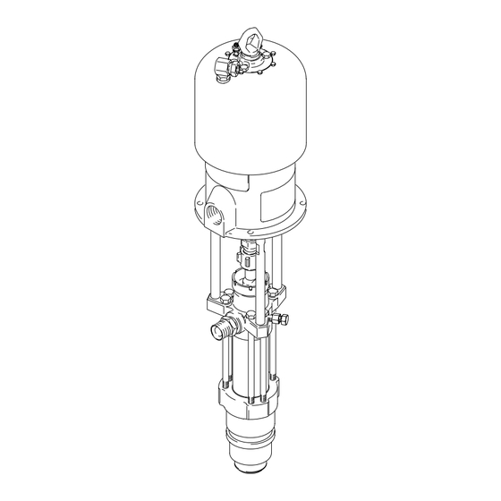
Part No.
222835
Shown
Rev. J
0913A
Advertisement

Related Manuals for Graco 222828


Summary of Contents for Graco 222828
- Page 1 10 MPa, 103 bar (1500 psi) Maximum Hydraulic Input Pressure Refer to page 2 for Table of Contents. 0913A GRACO INC. P.O. BOX 1441 MINNEAPOLIS, MN 55440–1441 ECOPYRIGHT 1992, GRACO INC. Graco Inc. is registered to I.S. EN ISO 9001...
- Page 2 ......Toll-Free Graco Phone Numbers ....
- Page 3 D This equipment is for professional use only. D Read all instruction manuals, tags, and labels before operating the equipment. D Use the equipment only for its intended purpose. If you are uncertain about usage, call your Graco distributor. D Do not alter or modify this equipment. Use only genuine Graco parts and accessories.
- Page 4 Permanently coupled hoses cannot be repaired; replace the entire hose. D Use only Graco approved hoses. Do not remove any spring guard that is used to help protect the hose from rupture caused by kinks or bends near the couplings.
- Page 5 WARNING FIRE AND EXPLOSION HAZARD Improper grounding, poor ventilation, open flames or sparks can cause a hazardous condition and result in a fire or explosion and serious injury. D Ground the equipment and the object being sprayed. Refer to Grounding on page 7. D If there is any static sparking or you feel an electric shock while using this equipment, stop spray- ing immediately.
- Page 6 Notes 308149...
- Page 7 Installation Grounding 6. Fluid supply container: according to your local code. WARNING 7. Object being sprayed: according to your local code. FIRE AND EXPLOSION HAZARD Before operating the pump, ground the 8. All solvent pails used when flushing, according to system as explained below.
- Page 8 Contact your Graco distributor for assis- tance in designing a system to suit your particular Accessories are available from your Graco distributor.
- Page 9 Installation (AIR-POWERED PUMPS) D A bleed-type master air valve (E) is required in SYSTEM ACCESSORIES your system to relieve air trapped between it and the air motor when the valve is closed (see the WARNING WARNING above). Be sure the bleed valve is easily accessible from the pump, and is located A bleed-type master air valve (E) and a fluid drain downstream from the air regulator.
- Page 10 It is very important to keep the hydraulic supply system clean at all times. Be sure that all hydraulic Accessories are available from your Graco . If you fluid lines are absolutely clean. Blow out the lines supply your own accessories, be sure they are ade- with air and flush thoroughly with solvent before quately sized and pressure-rated to meet the system’s...
- Page 11 Install the following accessories in the positions shown of hydraulic fluid. Use only Graco-approved hydraulic in Fig. 4, using adapters as necessary: oil. Order Part No. 169236, 5 gal. (19 liter) or 207428, 1 gal.
- Page 12 Close the bleeder valve when all air has been eliminated. Packing Nut/Wet-Cup Fill the packing nut/wet-cup (2) 1/3 full with Graco WARNING Throat Seal Liquid (TSL) or compatible solvent. See Fig. 5. Using the supplied wrench (104), adjust the To reduce the risk of fluid injection, do not use your packing nut weekly so it is just snug;...
- Page 13 Operation (AIR-POWERED MODELS) With the pump and lines primed, and with adequate air Always flush the pump before the fluid dries on the pressure and volume supplied, the pump will start and displacement rod. Never leave water or water-based stop as the gun/valve is opened and closed. In a fluid in the pump overnight.
- Page 14 Operation (HYDRAULIC-POWERED MODELS) Starting and Adjusting the Pump WARNING Supply fluid to the pump, per the requirements of your To reduce the risk of overpressurizing your system, system. which could result in component rupture and cause serious injury, never exceed 10 MPa, 103 bar Refer to Fig.
- Page 15 Turn on the air/hydraulic power just enough to start the pump. If the pump starts when the air/hydraulic power is turned on, the obstruction is in the fluid hose or gun. NOTE:If you experience air motor icing, contact your Graco distributor. 308149...
- Page 16 Service 1. Flush the pump, if possible. Stop the pump at the WARNING bottom of its stroke. Relieve the pressure. To reduce the risk of serious injury whenever you 2. Disconnect the air or hydraulic hose. Plug all are instructed to relieve pressure, always follow the hydraulic hoses immediately, to prevent contami- Pressure Relief Procedure on page 12.
- Page 17 Service King, Bulldog, and Premier Pumps Viscount Pumps (Model 222940 (Model 222835 Shown) Shown) 0914A Torque to 129–142 N.m (95–105 ft–lb). Square hole is for use with torque wrench. Torque to 196–210 N.m (145–155 ft–lb). Torque to 129–142 N.m (95–105 ft–lb). 01403B Torque to 135–169 N.m (100–125 ft–lb).
- Page 18 Fill the wet-cup (2) 1/3 full of pump while another reconnects it to the motor (see Graco Throat Seal Liquid or compatible solvent. the CAUTION above). Orient the pump’s fluid outlet to the air or hydraulic inlet as was noted in 6.
- Page 19 Service Displacement Pump Disassembly 8. Place the flats of the displacement rod (1) in a vise. Using a 13 mm (1/2 in.) diameter brass rod, When disassembling the pump, lay out all the removed pry the intake check valve assembly away from parts in sequence, to ease reassembly.
- Page 20 Service 10. Pull the seal (39) and seat (11) out the top of the intake housing (17). See Fig. 10. If the seat is difficult to remove, turn the housing upside down and drive the seat out using a hammer and brass rod.
- Page 21 Service THROAT PACKING DETAIL DETAIL OF PISTON CHECK VALVE 01120 DETAIL OF INTAKE CHECK VALVE Piston check valve (see detail at right) Intake check valve (see detail at right) Remove only if damaged. Remove and clean plug. Torque to 30–38 NSm (22–28 ft-lb) Inspect mating surfaces.
- Page 22 Service Reassembly 8. Lubricate the intake valve packings and the inner diameter of the valve body (10{). Install the pack- ings one at a time in the following order, with the Refer to Fig. 11 for reassembly. lips of the v-packings facing up: the female r v-packing (40*), one PTFE gland (41*), one...
- Page 23 Service THROAT PACKING DETAIL DETAIL OF PISTON CHECK VALVE 10 15 01120 Piston check valve DETAIL OF (see detail at right) INTAKE CHECK VALVE Intake check valve (see detail at right) Remove only if damaged. Torque to 156–171 N.m (115–126 ft–lb). Screw plug completely into valve housing.
- Page 24 Service 16. Lubricate the throat packings and glands, and install them in the outlet housing (19) one at a time in the following order, with the lips of the v-pack- ings facing down: the male gland (23*), one r v-packing PTFE UHMWPE v-packing (22*), one PTFE...
- Page 25 Parts Model 222828 Pump, Series A Model 222829 Pump, Series A 12:1 Ratio, with Bulldog Air Motor 12:1 Ratio, with Quiet Bulldog Air Motor 102} }107 102} }107 108} 108} 103} 103} }106 }106 0918A 0917A Part Part Description Description...
- Page 26 Parts Model 222835 Pump, Series B Model 222901 Pump, Series B 24:1 Ratio, with King Air Motor 24:1 Ratio, with Quiet King Air Motor 102} }107 102} }107 108} 108} 103} 103} }106 }106 0914A 0915A Part Part Description Description 245111 AIR MOTOR, King 220106...
- Page 27 Parts Model 222940 Pump, Series A Model 222902 Pump, Series B 39:1 Ratio, with Premier Air Motor with Viscount Hydraulic Motor 102} }107 102} }107 109} 108} 103} 108} }106 103} }106 0916A 01403B Part Part Description Description 222800 AIR MOTOR, Premier 235345 HYDRAULIC MOTOR, Viscount See 308213 for parts...
- Page 28 Parts Model 222810, Series B Displacement Pump 39*{ 0919A 308149...
- Page 29 Parts PTFE Model 222810, Series B Packing Conversion Kit 222861 Displacement Pump Use to convert the pump to all PTFE throat and intake Part packings. Must be purchased separately. Includes instruc- Description tions. 184002 ROD, displacement; sst Leather Packing Conversion Kit 222862 184006 PACKING NUT/WET-CUP;...
- Page 30 Technical Data (Model 222828 Bulldog Pump) Ratio ..........
- Page 31 Technical Data (Model 222829 Quiet Bulldog Pump) Ratio ..........12:1 (Quiet Bulldog Air Motor) Maximum fluid working pressure .
- Page 32 Technical Data (Model 222835 King Pump) Ratio ..........24:1 (Standard King Air Motor) Maximum fluid working pressure .
- Page 33 Technical Data (Model 222901 Quiet King Pump) Ratio ........... . 24:1 (Quiet King Air Motor) Maximum fluid working pressure .
- Page 34 Technical Data (Model 222940 Premier Pump) Ratio ............39:1 (Premier Air Motor) Maximum fluid working pressure .
- Page 35 Technical Data (Model 222902 Viscount Pump) Maximum fluid working pressure ......15.9 MPa, 159 bar (2300 psi) Maximum hydraulic oil input pressure .
- Page 36 Dimensions Model 222835 Shown 0913 Pump Model 222828 1333.6 mm 540.5 mm 793.1 mm 664.7 mm 256.8 mm (52.5 in.) (21.28 in.) (31.22 in.) (26.17 in.) (10.11 in.) 222829 1349.1 mm 556 mm 793.1 mm 664.7 mm 256.8 mm (53.11 in.) (21.89 in.)
- Page 37 Mounting Hole Layouts Bulldog, King, and Viscount Pumps 94.28 mm (3.712”) 101.6 mm 94.28 mm (4.0”) (3.712”) 50.8 mm (2.0”) 11.1 mm (0.437”) DIA (4) Three M16 x 2.0 88 mm Holes (3.464”) 0653 Premier Pumps 135.0 mm 67.5 mm (5.3 in.) (2.7 in.) 116.9 mm...
- Page 38 Graco distributor to the original purchaser for use. With the exception of any special, extended, or limited warranty published by Graco, Graco will, for a period of twelve months from the date of sale, repair or replace any part of the equipment determined by Graco to be defective.
Need help?
Do you have a question about the 222828 and is the answer not in the manual?
Questions and answers