Table of Contents
Advertisement
Quick Links
Instructions-Parts List
CARBON STEEL
Check-Matet450 Pumps
WITH PRIMING PISTON, AND
SEVERE-DUTY ROD AND CYLINDER
U.S. Patent Nos. 5,147,188 and 5,154,532.
Important Safety Instructions
Read all warnings and instructions in this manual.
Save these instructions.
Table of Contents
. . . . . . . . . . . . . . . . . . . . . . . . . . . . . . . . . .
. . . . . . . . . . . . . . . . . . . . . . . . . . . . . . . . . . . . . .
. . . . . . . . . . . . . . . . . . . . . . . . . . . . . . . . . . . . . .
. . . . . . . . . . . . . . . . . . . . . . . . . . . . . . . . . . . . .
. . . . . . . . . . . . . . . . . . . . . . . . . . . . . . . . . . . . .
Service
. . . . . . . . . . . . . . . . . . . . . . . . . . . .
. . . . . . . . . . . . . . . . . . . . . . . . . . . . .
. . . . . . . . . . . . . . . . . . . . . . . . . . . . . . . . . . . . . . . .
. . . . . . . . . . . . . . . . . . . . . . . . . . . . . . . . . . .
. . . . . . . . . . . . . . . . . . . . . . . . . .
. . . . . . . . . . . . . . . . . . . . . . . . . . . . . . . . . . . . .
. . . . . . . . . . . . . . . . . . . . . . . . . . . . .
http://gracomanual.com
2
3
3
6
9
12
14
. . . . . . . .
14
. . . . . . . .
15
. . . . . . . . . . . . . . . . .
16
23
. . . . . . . . . .
33
46
47
48
48
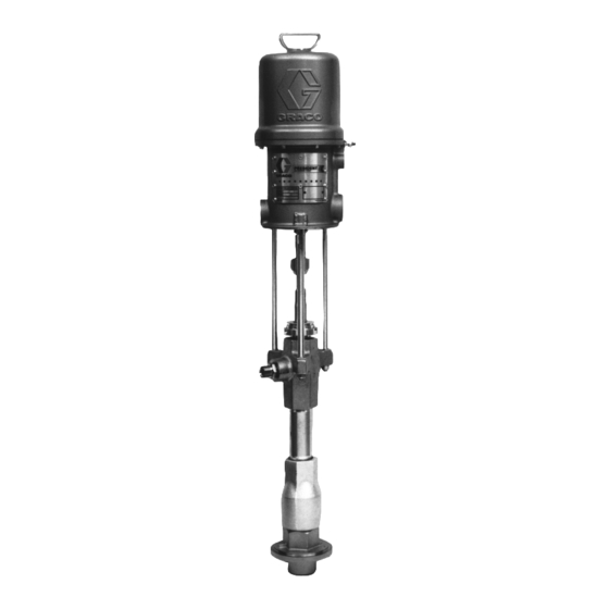
Model 222768 Shown
308017W
0423A
Advertisement
Table of Contents

Related Manuals for Graco Check-Mate 450


Summary of Contents for Graco Check-Mate 450
-
Page 1: Table Of Contents
........Graco Information ...... -
Page 2: List Of Models
List of Models Maximum Air Maximum Fluid Working Pressure Working Pressure Model No. Description 222770 10:1 ratio Monarkr Pump, Series A 1800 (UHMWPE/PTFE Packed) 235626 10:1 ratio Monarkr Pump, Series A 1800 (PTFE Packed) 222768 20:1 ratio Presidentr Pump, Series A 3600 (UHMWPE/PTFE Packed) 237207... -
Page 3: Symbols
D This equipment is for professional use only. D Read all instruction manuals, tags, and labels before operating the equipment. D Use the equipment only for its intended purpose. If you are uncertain about usage, call your Graco distributor. D Do not alter or modify this equipment. Use only genuine Graco parts and accessories. - Page 4 Permanently coupled hoses cannot be repaired; replace the entire hose. D Use only Graco approved hoses. Do not remove any spring guard that is used to help protect the hose from rupture caused by kinks or bends near the couplings.
- Page 5 WARNING FIRE AND EXPLOSION HAZARD Improper grounding, poor ventilation, open flames or sparks can cause a hazardous condition and result in a fire or explosion and serious injury. D Ground the equipment and the object being sprayed. Refer to Grounding on page 8. D If there is any static sparking or you feel an electric shock while using this equipment, stop spray- ing/dispensing immediately.
-
Page 6: Installation
D A red-handled main air bleed valve (V) is re- quired in your system to shut off the air supply to NOTE: Always use Genuine Graco Parts and Acces- the pump and ram (see the WARNING at left). sories, available from your Graco distributor. Refer to When closed, the valve will bleed off all air in the the Product Data Sheet, Form No. - Page 7 Installation D A gun or dispense valve (N) dispenses the fluid. Fluid Line Accessories The gun shown in Fig. 1 is a high pressure dispens- Install the following accessories in the positions shown ing gun for highly viscous fluids. in Fig. 1, using adapters as necessary: D Install a fluid drain valve (L) in a tee near the D A gun/valve swivel (P) allows freer gun/valve pump fluid outlet.
- Page 8 Installation Grounding 4. Spray gun/dispense valve: ground through connec- tion to a properly grounded fluid hose and pump. WARNING 5. Fluid supply container: follow your local code. FIRE AND EXPLOSION HAZARD 6. Object being sprayed: follow your local code. Before operating the pump, ground the system as explained below.
-
Page 9: Operation
Operation Pressure Relief Procedure Packing Nut/Wet-Cup Before starting, fill the packing nut (2) 1/3 full with Graco Throat Seal Liquid (TSL) or compatible solvent. WARNING See Fig. 3. SKIN INJECTION HAZARD The system pressure must be manually WARNING relieved to prevent the system from starting or dispensing accidentally. - Page 10 Operation Flush the Pump Before First Use 6. Slowly open the air regulator (H) until the pump starts. The pump is tested with lightweight oil, which is left in to protect the pump parts. If the fluid you are using 7.
- Page 11 Operation Starting and Adjusting the Pump Flushing (continued) WARNING 10. With the pump and lines primed, and with ade- quate air pressure and volume supplied, the pump FIRE AND EXPLOSION HAZARD will start and stop as you open and close the Before operating the pump, read the gun/valve.
-
Page 12: Troubleshooting
Troubleshooting 1. Relieve the pressure. WARNING 2. Check all possible problems and causes before To reduce the risk of serious injury whenever you disassembling the pump. are instructed to relieve pressure, always follow the Pressure Relief Procedure on page 9. PROBLEM CAUSE SOLUTION... - Page 13 Troubleshooting PROBLEM CAUSE SOLUTION Erratic or accelerated Exhausted fluid supply. Refill and prime. pump speed. Fluid is too heavy for pump priming. Use the bleeder valve (see page 10); use a ram. Held open or worn piston valve or seals. Clear the valve; replace the seals. Held open or worn priming piston.
-
Page 14: Required Tools
Service Required Tools 2. Relieve the pressure. D Torque wrench 3. Disconnect the air hose. Hold the fluid outlet fitting D Bench vise, with soft jaws (8) with a wrench to keep it from being loosened D Rubber mallet while you disconnect the fluid hose. D Hammer D O-ring pick 4. -
Page 15: Reconnecting The Displacement Pump
7. Mount the pump and reconnect all hoses. Recon- nect the ground wire if it was disconnected. Fill the wet-cup (2) 1/3 full of Graco Throat Seal Liquid or compatible solvent. 8. Turn on the air supply. Run the pump slowly to ensure proper operation. -
Page 16: Displacement Pump Service
Service Displacement Pump Service 5. Use an o-ring pick to remove the seal (21) from the intake valve housing (17). Discard the seal; use a new one for reassembly. Pull the intake Disassembly valve seat (22) out the bottom of the housing (17). When disassembling the pump, lay out all removed If the seat is difficult to remove, insert a brass rod parts in sequence, to ease reassembly. - Page 17 Service Throat Packing Detail Lips of v-packings must face down. See Detail at right. Valve Plug (remove and clean). Valve Body (do not remove). Remove only if damaged. Detail of Piston and Intake Check Valve (Ref) (Ref) (Ref) (Ref) 0425B Fig.
- Page 18 Service 13. Place the flats of the piston seat (16) in a vise. 14. To disassemble the intake check valve (DD), place Using a 13 mm (1/2 in.) dia. brass rod (EE), un- the nut (18) in a vise and unscrew the intake valve screw the piston guide (14) from the piston seat body (19), using a 28 mm wrench.
- Page 19 Service Reassembly (Refer to Fig. 8) NOTE: The piston spacer (33) is not required when pumping fluids with a viscosity greater than 1 million 1. Place a 13 mm (1/2 in.) diameter brass rod length- centipoise. wise in a vise. Install a new piston seal (15*) on the piston seat.
- Page 20 Service 6. Lubricate the throat packings and glands, and 12. Place a 26 mm wrench on the flats of the packing install them in the outlet housing (10) one at a time nut (18) and a 28 mm wrench on the flats of the in the following order, with the lips of the v-pack- valve body (19).
- Page 21 Service Lips of v-packings must face down. Throat Packing Detail See Detail at right. Lubricate threads and screw completely into body (43). Torque to 30–38 N.m (22–28 ft-lb). Valve Body (bleed hole must face down). Apply thread sealant. Large bevel must face down. Flat side must face up.
- Page 22 Notes 308017...
-
Page 23: Parts
Parts Model 222770, Series A 10:1 Ratio Monark Pump (UHMWPE and PTFE Packed) Model 235626, Series A 10:1 Ratio Monark Pump (PTFE Packed) Ref. Part No. Description Qty. 111n 222791 AIR MOTOR, Monark See 307043 for parts 102n 24B190 KIT, tie rod 184092 ROD, adapter 104n 184059... - Page 24 Parts Model 222768, Series A Model 237207, Series A 20:1 Ratio President Pump 20:1 Ratio Stubby President Pump (UHMWPE and PTFE Packed) (UHMWPE and PTFE Packed) Ref. Ref. Part No. Description Qty. Part No. Description Qty. 222772 AIR MOTOR, President 222772 AIR MOTOR, President See 306982 for parts...
- Page 25 Parts Model 246933, Series A 20:1 Ratio President Pump (Tuffstack Throat Packed) Ref. Part No. Description Qty. 222772 AIR MOTOR, President See 306982 for parts 102n 24B190 KIT, tie rod 184091 ROD, adapter 104n 184059 NUT, coupling 105n 184128 COLLAR, coupling 106n 109209 NUT, hex, self-locking;...
- Page 26 Parts Model 222769, Series A 34:1 Ratio Senator Pump (shown) (UHMWPE and PTFE Packed) Model 224660, Series A 34:1 Ratio Quiet Senator Pump (UHMWPE and PTFE Packed) Ref. Part No. Description Qty. 217540 AIR MOTOR, Senator, standard Used on Model 222769; See 307592 for parts 220571 AIR MOTOR, Senator, quiet...
- Page 27 Parts Model 237492, Series A 34:1 Ratio Stubby Senator Pump (shown) (UHMWPE and PTFE Packed) Model 237780, Series A 34:1 Ratio Stubby Quiet Senator Pump (UHMWPE and PTFE Packed) Ref. Part No. Description Qty. 217540 AIR MOTOR, Senator, standard Used on Model 237492; See 307592 for parts 220571 AIR MOTOR, Senator, quiet...
- Page 28 Parts Model 222778, Series A 55:1 Ratio Bulldog Pump (shown) (UHMWPE and PTFE Packed) Model 222813, Series A 55:1 Ratio Quiet Bulldog Pump (UHMWPE and PTFE Packed) Ref. Part No. Description Qty. 208356 AIR MOTOR, Bulldog, standard Used on Model 222778 See 307049 for parts 215255 AIR MOTOR, Bulldog, quiet...
- Page 29 Parts Model 237208, Series A 55:1 Ratio Stubby Bulldog Pump (shown) (UHMWPE and PTFE Packed) Model 237779, Series A 55:1 Ratio Stubby Quiet Bulldog Pump (UHMWPE and PTFE Packed) Ref. Part No. Description Qty. 208356 AIR MOTOR, Bulldog, standard Used on Model 237208 See 307049 for parts 215255 AIR MOTOR, Bulldog, quiet...
- Page 30 Displacement Pump Parts NOTE: Refer to page 32 for the available throat packing kits. Model 222790, Series B Displacement Pump, UHMWPE and PTFE Packings Model 235540, Series A Displacement Pump, PTFE Packings Model 237206, Series A Displacement Pump, UHMWPE and PTFE Packings, Stubby Pump Model 237450, Series A Displacement Pump, UHMWPE and PTFE Packings, Stubby Pump Model 246932, Series A Displacement Pump, Tuffstack throat, UHMWPE and PTFE Packings Ref.
- Page 31 Displacement Pump Parts Model 222790 Shown Refer to page 32 for available throat packing kits. Seal Repair Kit 222773 does not include Piston Seal 188257 or Intake Valve Seal 189217 used on pump 235540. Intake Seat Repair Kit 222793 does not include Intake Valve Seal 189217 used on pump 235540. Used on Models 222790, 235540, and 237206 only.
- Page 32 Throat Packing Kits UHMWPE and PTFE Throat Packing Repair Kit 222774, used on Displacement Pumps 222790, 237206, and 237450 Ref. Lips of v-packings must face down. Part No. Description Qty. 109302 V-PACKING; PTFE 184172 GLAND, female; sst 109252 V-PACKING; UHMWPE 184222 GLAND, male;...
-
Page 33: Technical Data And Performance Charts
Technical Data (Monark Pumps) WARNING Be sure that all fluids and solvents used are chemically compatible with the Wetted Parts listed below. Always read the manufacturer’s literature before using fluid or solvent in this pump. Category Data Ratio 10:1 Maximum fluid working pressure 12 MPa, 124 bar (1800 psi) Maximum air input pressure 1.2 MPa, 12 bar (180 psi) - Page 34 Technical Data (Monark Pumps) KEY: Fluid Outlet Pressure - Black Curves Air Consumption - Gray Curves 1.2 MPa, 12 bar (180 psi) Air Pressure 0.7 MPa, 7 bar (100 psi) Air Pressure 0.49 MPa, 4.9 bar (70 psi) Air Pressure cycles/min cycles/min 1800...
- Page 35 Technical Data (President Pumps) WARNING Be sure that all fluids and solvents used are chemically compatible with the Wetted Parts listed below. Always read the manufacturer’s literature before using fluid or solvent in this pump. Category Data Ratio 20:1 Maximum fluid working pressure 25 MPa, 248 bar (3600 psi) Maximum air input pressure 1.2 MPa, 12 bar (180 psi)
- Page 36 Technical Data (President Pumps) KEY: Fluid Outlet Pressure - Black Curves Air Consumption - Gray Curves 1.2 MPa, 12 bar (180 psi) Air Pressure 0.7 MPa, 7 bar (100 psi) Air Pressure 0.49 MPa, 4.9 bar (70 psi) Air Pressure 0.28 MPa, 2.8 bar (40 psi) Air Pressure cycles/min cycles/min...
- Page 37 Technical Data (Senator Pumps) WARNING Be sure that all fluids and solvents used are chemically compatible with the Wetted Parts listed below. Always read the manufacturer’s literature before using fluid or solvent in this pump. Category Data Ratio 34:1 Maximum fluid working pressure 28 MPa, 281 bar (4080 psi) Maximum air input pressure 0.8 MPa, 8 bar (120 psi)
- Page 38 Technical Data (Senator Pumps) KEY: Fluid Outlet Pressure - Black Curves Air Consumption - Gray Curves 0.7 MPa, 7 bar (100 psi) Air Pressure 0.49 MPa, 4.9 bar (70 psi) Air Pressure 0.28 MPa, 2.8 bar (40 psi) Air Pressure cycles/min cycles/min 3600...
- Page 39 Technical Data (Quiet Senator Pumps) WARNING Be sure that all fluids and solvents used are chemically compatible with the Wetted Parts listed below. Always read the manufacturer’s literature before using fluid or solvent in this pump. Category Data Ratio 34:1 Maximum fluid working pressure 28 MPa, 281 bar (4080 psi) Maximum air input pressure...
- Page 40 Technical Data (Quiet Senator Pumps) KEY: Fluid Outlet Pressure - Black Curves Air Consumption - Gray Curves 0.7 MPa, 7 bar (100 psi) Air Pressure 0.49 MPa, 4.9 bar (70 psi) Air Pressure 0.28 MPa, 2.8 bar (40 psi) Air Pressure cycles/min cycles/min 3600...
- Page 41 Technical Data (Bulldog Pumps) WARNING Be sure that all fluids and solvents used are chemically compatible with the Wetted Parts listed below. Always read the manufacturer’s literature before using fluid or solvent in this pump. Category Data Ratio 55:1 Maximum fluid working pressure 34 MPa, 341 bar (4950 psi) Maximum air input pressure 0.6 MPa, 6.2 bar (90 psi)
- Page 42 Technical Data (Bulldog Pumps) KEY: Fluid Outlet Pressure - Black Curves Air Consumption - Gray Curves 0.6 MPa, 6.2 bar (90 psi) Air Pressure 0.49 MPa, 4.9 bar (70 psi) Air Pressure 0.28 MPa, 2.8 bar (40 psi) Air Pressure cycles/min cycles/min 5000...
- Page 43 Technical Data (Quiet Bulldog Pumps) WARNING Be sure that all fluids and solvents used are chemically compatible with the Wetted Parts listed below. Always read the manufacturer’s literature before using fluid or solvent in this pump. Category Data Ratio 55:1 Maximum fluid working pressure 34 MPa, 341 bar (4950 psi) Maximum air input pressure...
- Page 44 Technical Data (Quiet Bulldog Pumps) KEY: Fluid Outlet Pressure - Black Curves Air Consumption - Gray Curves 0.6 MPa, 6.2 bar (90 psi) Air Pressure 0.49 MPa, 4.9 bar (70 psi) Air Pressure 0.28 MPa, 2.8 bar (40 psi) Air Pressure cycles/min cycles/min 5000...
- Page 45 Notes 308017...
-
Page 46: Dimensions
Dimensions Model 222768 Shown 0423A Pump Model (air inlet) (fluid outlet) 222770, 1188 mm 365 mm 826 mm 328 mm 3/8 npt(f) 3/4 npt(m) 235626 (46.25 in.) (14.35 in.) (32.5 in.) (12.9 in.) 222768, 1251 mm 418 mm 832 mm 328 mm 1/2 npt(f) 3/4 npt(m) -
Page 47: Mounting Hole Layout
Mounting Hole Layout PRESIDENT PUMPS MONARK PUMPS 63.5 mm 54.1 mm 63.5 mm (2.50”) (2.130”) (2.50”) 22.2 mm 62.50 mm (0.875”) (2.461”) 31.25 mm 38.5 mm (1.230”) (1.516”) 31.2 mm (1.230”) 62.50 mm (2.461”) 7.1 mm 7.9 mm (0.281”) 11.4 mm (0.312”) diameter (2) (0.449”) -
Page 48: Warranty
With the exception of any special, extended, or limited warranty published by Graco, Graco will, for a period of twelve months from the date of sale, repair or replace any part of the equipment determined by Graco to be defective.
Need help?
Do you have a question about the Check-Mate 450 and is the answer not in the manual?
Questions and answers